
CHAPTER 9 Specification
INTRODUCTION
It is now time to put a sound system together in order to fill a space with sound. We will need to move beyond the simplicity of speaker order and define speaker coverage with more precision so that we can shape the sound to the contours of the room. The sound system will be a carefully constructed assemblage of parts, each of which has a defined role to play. The definition of such roles will be essential for the on-site deconstruction and reconstruction process that will follow: optimization.
Specification is the culmination of the design process. We have considered the transmission path and the challenges that we are likely to encounter en route. We have learned how the sound system will be perceived by the audience members. We understand the role that the room acoustics will play. We know how to read the plans for the space and we will use our power of prediction to choose the best locations, the array types, the speaker elements, and the signal processing that drives them. We understand the shapes that are available to us for making minimum variance designs. In short, every chapter of this book has provided information that leads us to this point of ultimate decision: specification.
specification n. specifying or being specified; specified detail, esp. (in pl) detailed description of construction, workmanship, materials, etc., of work (to be) undertaken, prepared by architect, engineer, etc. design n. 1. mental plan; scheme of attack. 2. purpose; end in view; adaptation of means to ends. 3. preliminary sketch for picture, plan of building, machine, etc.; arrangement of lines, drawing, etc. 4. established form of a product; general idea, construction from parts
Concise Oxford Dictionary
PRINCIPLES OF SPECIFICATION
Specification defined
The end result of the design process will be a series of documents that will be used to acquire and install a sound system. The list will include drawings of the room with speaker locations, flow block diagrams, equipment lists, and more. There are potentially endless levels of documentation that can be supplied for a particular installation. The specification may include conduit size, terminal strip model number and labeling, and more. For our purposes here, we will limit the specification scope to those items related to the optimized design as outlined in this book. These include the main components of the speaker system that will have critical effects on minimum variance, rather than the details such as cabling. This is not to say that these other details are less important. They are, however, well covered in other texts that focus on the nuts and bolts of system installation.
The specification arises from the particular needs of a client. The specifications are the final answers to a series of questions that flow between the designer and the client. We find out what the client wants and what they are willing to do to get it. We will need input from the client as to their expectations and they will need input from us as to what is feasible within the framework of optimized design guidelines. It is not expected that clients will tailor their expectations to what is realistically achievable. They may advocate for particular features that will make optimized design impossible. There may be architectural features that will degrade uniformity in some areas. There are certain to be cost issues.
Compromise
The process of sound system design is always one of compromise, but that does not mean we need to compromise our principles. There is no job where we will have unlimited budget and placement options. It is our job to inform the client of the quality implications of the limits placed on our design. Then all parties can seek to reach a suitable compromise or a creative solution based on the weight of the other factors involved. There will be times when we have to make decisions that will have both positive and negative effects. How can we make these choices? Let's take some guidance from others.
TANSTAAFL
Science fiction author Robert Heinlein created the TANSTAAFL principle in his 1966 novel, The Moon Is a Harsh Mistress. This term (pronounced “t-ahn-st-ah-ful”) is an abbreviation for “There ain't no such thing as a free lunch.” The concept is informative in all walks of life and no less applicable to our decision-making process in system specification. Every decision we make comes with a cost, some form of tradeoff. This theme will be central to this chapter, as we will attempt to maintain a focus on the nature of the tradeoffs we are making. Let's begin with a simple illustration: the overlap of two speakers in a point source array. Increased overlap yields higher power capability for narrower combined coverage angle and higher variance. Decreased overlap yields minimal power addition, expanded coverage angle, and minimum variance. We must evaluate which is more important, and this is often a difficult choice. If the power capability is too low the system will be run into hard overload. This is a far worse result than frequency response ripple variance due to overlap-induced comb filtering.
Sales and marketing departments are trained to suppress our consideration of TANSTAAFL. Each day an assortment of free offers are presented to us. All have strings attached. We must not lose sight of this guiding principle. We must be realistic about the consequences of the choices we make. If it seems too good to be true, it is.
Perspectives: I am not sure there is any “best” way to do anything. All solutions seem to be compromises in some way. The trick is to minimize the compromises in the total system, and that takes in all the elements in a performance or event space. Sound is only one part of a much larger system.
Alexander Yuill-Thornton II (Thorny)
Perspectives: While it is nice to have a “perfect” system, with the best of everything, this is not always possible, or maybe necessary. Large systems in large spaces are hindered by long reverberation times and slap reflections. Spending lots of time auditioning very fine microphone preamps or other processing equipment might be better spent on refining the basic system design or doing a better job of directing the speakers and optimizing the system. Toys are nice, but can be easily swamped by the nature of the beast.
Alexander Yuill-Thornton II (Thorny)
ACOUSTIC TRIAGE
The medical community has developed a resource allocation and prioritization system that is implemented under emergency conditions. This system is known as “triage” and distributes resources based on a combination of probability of success and degree of need. The triage system seeks to prevent excessive allocation of resources for lost causes, and prioritizes those with minor problems at the bottom of the list. There is no point in using up the entire blood bank and all of the surgical facilities for a single doomed patient when these precious resources can be used to save hundreds who still have a fighting chance. On the other end, it would be imprudent to treat those with bruised toes ahead of those who are in critical yet recoverable condition.
In our acoustic triage model, we seek to identify areas that will require special care. We will seek to create and spread our resources for maximum benefit to the largest areas. We seek to prevent solutions for one area that create problems for others. If this is the case, we will use the principles of triage to help our decision-making. An example: there is a small distant balcony area. This can be covered by upward aiming of the speakers in the main cluster. This will result in excellent imaging for the balcony seats. The presence of a 10-m-tall mirrored wall directly above the top row gives rise to concerns about reflections that will disturb the rest of the room and the stage. Triage principles do not require us to abandon these seats but rather to seek an alternative solution. Over-balcony fill speakers can cover this area with minimal risk to the surrounding areas. The imaging will suffer upstairs but this might be considered a reasonable tradeoff.
The principles of minimum variance, TANSTAAFL, and triage are the philosophical underpinnings of our specification strategies. They combine to create an approach that seeks the maximum benefit for the majority, is realistic about the tradeoffs required, and is committed to allocation of the resources to the areas where tangible benefits can be assured.
CHANNEL/SYSTEM TYPES
There are several roles that channels can play. The most straightforward is the role of a main system such as the center cluster that reinforces speech. Stereo mains in a concert setting play a similar role with the added dimension of horizontal panorama for some listeners. In either case, this system is charged with the principal responsibility of coverage for the majority of the program material. These will be termed main systems.
A very different part is played by speakers fed by the surround channels. They might be used only sparingly for a spatial enhancement or special effect, hence the term effects system. Such speakers provide a strictly auxiliary role, independent of the main system. Their relationship to the main systems at any given moment is entirely under artistic jurisdiction. It is assumed that the relationship between the effects system and the mains (or other effects systems) will fail the stable summation criteria outlined in Chapter 2. As a result, we will design and optimize these types of channels as unrelated roommates that share the common space.
The design requirements for each channel will be assessed separately. The needs of the left surround speakers are distinct from those of the left mains, or any other channel. The components dedicated to the transmission of a particular channel comprise a system. A system can have a single speaker or any number above that. There is an important distinction between systems and subsystems. A system can comprise multiple subsystems driven by the same source channel. The job of the system is to fill the space. Not all spaces are amenable to optimal coverage by a single speaker or a fully symmetric array alone. Such spaces require subdivision of the coverage into separate speakers with adjustable parameters. Subsystems share the space, and the goals of the particular source channel.
Mono
A monaural system is charged with filling the entire listening space with the primary transmission signal. Straightforward and simple, this mainstay system can include an unlimited number of related subsystems. All subsystems share a common desired sonic image location and relative level.
General design principles for monaural systems:
■ Center cluster (coupled point source) is the standard. Alternative is the dual mono system located on the left and right of the stage.
■ Related subsystems should reconcile to a shared approximate point source to cluster(s) and/or performers.
■ Subsystems should be scaled as appropriate for their relative throw distance.
■ Subdivide when appropriate in order to level compensate for different distances, to minimize reflections, improve sonic image, or reach obstructed areas.
Stereo
Stereo systems are a hybridization of two separate channels and two matched channels. The amount of separation of the input signals is an open variable under artistic control. The stable summation criteria cannot be met under these circumstances and therefore the design and optimization must proceed with the channels seen as unrelated. Each channel of a stereo system can include an unlimited number of related subsystems. The benefits of stereo can be evaluated by the TANSTAAFL and triage principles. Stereo requires overlap from separated sources. This is certain to increase variance. After all, stereo is a form of desirable variance. The benefits to the central area must outweigh the costs on the sides. The triage principle allows us to evaluate when to stop the bleeding on the sides and let them live with a single clear channel
General design principles for stereo systems:
■ Horizontal overlap is required in the center seating area.
■ Be mindful of the nonscalable time offset considerations regarding stereo imaging. Keep the stereo overlap in the zones within a 10 ms time offset as much as possible.
■ Stereo auxiliary systems are rarely worth the effort and expense and loss of coherence. Examples include stereo under-balcony delays, alternating left/right schemes in the round, etc.
■ If the stereo spacing is too narrow it is not worth the trouble. Examples of this include center clusters that are split into stereo (yes, people have done this!).
Surround
The role of a surround system is to provide perimeter sound sourcing. Left and right surrounds contrast with their stereo counterparts just as headphone stereo perception differs from our living room. When listening to stereo in a room, the panoramic horizon remains in front of us at all times, even if the signal is panned to just one side. In surround sound, like headphones, a left side signal is truly arriving from that direction. Surrounds can be used to purposefully move our attention to a perimeter location or to envelop listeners inside of a fully multi-dimensional soundscape.
The surrounds are typically spaced along the side and rear walls as an uncoupled line source array in the horizontal plane. In multi-level halls, we will find additional sets of surrounds on each level to cover path obstructed areas.
From the design point of view, there are several notable aspects. Since surrounds are located on the side and rear walls, it is an absolute certainty that we will have a very high range ratio between the nearby seats and those at the center and opposite side. In our ideal world, we can reach deep into the hall and provide localization to a large area without overpowering and annoying the nearby seats. It will be to our advantage to move the speakers up as high as practical, thus reducing the range ratio. This has its limits, sometimes physical ones, such as ceilings and balconies. Other limits include excessive vertical image lift and reverberation. In many cases, we will employ excess pink shift to our advantage. When practical limitations leave us with far too much proximity ratio we can use pink-shift-induced “false sonic perspective” to give us more breathing room with the local listeners (see Chapter 3). The technique is to purposely aim the speakers so that the nearby seats are out of the coverage pattern. Additional help can be found in a highly directional speaker, provided it is aimed in the direction of the seats at the opposite side of the hall. This is one application where a third-order speaker is well suited to solo coverage. Why? The excess pink shift in the local area gives the listeners the perception that they are more distant from the source. As the distance increases, we move more onaxis and the pink shift decreases, yielding a net offset of effects. If the sound is going to be too loud in some locations, it is preferable for it to have the HF rolled off.
It is important to remember that each surround channel is charged with covering the full space, not to subdivide coverage as we would do with related subsystems. Surround speakers will provide the most uniform experience if they are aimed far across the space. Left is aimed at right and the rears are aimed at the front row. The worst thing we can do is aim the left surrounds down to cover the left and the right to cover the right, etc.
The reason a typical surround sound array is an uncoupled line source along the wall is due to the high proximity to listeners on the sides and to provide a sound image that appears along the wall. A coupled point source would be a poor choice here since it would provide pinpoint imaging, rather than a general direction. The range limits of the uncoupled point source leave us to consider a design dilemma. TANSTAAFL: if the spacing and number of elements is sufficient to cover the nearest listeners, it is certain to be highly overlapped on the opposite side. If we design for minimum overlap on the opposite side, large portions of the hall will be in the gap coverage zone. Triage: design the coverage range to end between the one-fourth and one-half point of the listening shape. (The unity crossover line is found at half of that distance.) Those listeners beyond the limit line will have excess overlap (ripple variance). Those listeners closer than the unity spatial crossover will have excess pink shift (spectral variance).
Each seating level (balconies, etc.) will require local surround sources.
General design principles for surrounds:
■ Uncoupled line source comprising first-order elements is the standard choice.
■ Subdivide when appropriate in order to level compensate for different distances.
■ Minimize the vertical range ratio as much as practical.
■ Space the speakers (horizontal) by the aspect ratio method for one-fourth to one-half of the coverage depth. Expect overlap coverage in the distant areas.
■ Aim speakers (vertical) by the asymmetric method (most distant seat) to reduce excess level in the near areas.
■ Subdivide coverage for different seating levels (first floor, second floor, etc.).
■ Delay is not required except in special cases such as speakers mounted on the balcony front that related to rear wall surrounds.
Source effects
It is sometimes desirable to localize to an exact point in the room for a moment. This is standard fare in the theatrical community, where a sound source is required to augment a particular cue on (or off) stage. The best way to achieve this is a source speaker at the desired location, often hidden inside set pieces. Such systems may have any power level and array type, and may even have related subsystems. From our point of view, this system will be designed and optimized as a stand-alone entity that covers the entire listening area.
Perspectives: These days line arrays are very fashionable. People are using them for everything. Even in situations when they are the worst of tools. Don't get me wrong. I too like line arrays, but to use them in old Italian (horseshoe) theaters where the requirement is short throw and extended vertical coverage is at least a questionable choice. These places usually require less powerful crystal clear multipoint designs.
Miguel Lourtie
SYSTEM SUBDIVISION
The term subdivision here connotes the creation of subsystems that carry copies of a shared original source waveform. The purpose of subdivision is to tailor the response for the particular coverage shape. If this is a match for the shape created by the speaker system when all elements are identically driven, there is no reason to bear the additional expense of subdivision. If the array coverage shape is not compliant to the listening area shape we will need to introduce separate level controls.
System subdivision concerns four types of differentiation: speaker type, level, delay, and equalization. If different speaker models covering the same frequency range are used, it is mandatory that the remaining parameters be separated. If matched speakers are driven at different levels, then delay and equalization should also be separated. Equalization is the last of the parameters to separate, and is rarely found in isolation.
System subdivision is a countermeasure to asymmetry and complexity. How much asymmetry is required before subdivision is required? Let's be practical and apply TANSTAAFL. Every subdivision has the costs of the material, installation, ongoing maintenance, and calibration time. It also opens up the door for human error. A good practical guideline is the 1.4 rule, also known as 3 dB. If two same model speakers have throw distances that differ by more than a ratio of 1.4, subdivision is indicated. For example, a three-element cluster with outer elements that have a different throw distance than the center unit can be evaluated this way.
Once level asymmetry is introduced, delay and equalization follow suit. We have to assume that a speaker that is run at a different level is operating at a different range of coverage length. Why else would we change the level? This is a different acoustical situation. Separate EQ is indicated. If the level is offset between two devices then the spatial crossover is not at the equidistant point between them. Delay is indicated, the amount of which is proportional to the level offset and physical displacement between the elements. If the level offset is small and the geometry of the enclosures allows for extremely low displacement it may be deemed impractical. In such cases, the delay required to phase-align the asymmetric spatial crossover is extremely minute and may not be worth the expense, trouble, and (most importantly) risk of error. It is often said that “line array” speakers do not require delay tapering. Remember that no element can be termed an “array” until it is placed in combination with others. Since we have already eliminated the coupled line source from the minimum variance menu, there is little need to enter the delay debate there. Suffice to say that coupled speakers lacking some measure of acoustic subdivision (angular isolation) cannot reap much benefit from electronic subdivision in any form, whether it is level, EQ, or delay. Our applications for the “line array” products are highly overlapped versions of the asymmetric coupled point source. These will have asymmetric spatial crossovers wherever asymmetric conditions are found along the way. In large arrays, gratuitous amounts of angular and level asymmetry may create a beast much more complicated to disentangle than we can handle. A practical strategy for arrays with high quantities of elements is described later in this chapter, where the role of delay tapering in that application will be described. To be on the safe side, if there is a level break, have EQ and delay at the ready.
Perspectives: Anticipate optimization. As I design a system for a particular use, I think about how I will go about bringing it up and the possible equalization strategies I might use. More than once this process has changed some of the design decisions I have made. I feel that as a designer I am responsible for the system's design, how to best optimize it, and how to get the most out of it when it is used. When I don't manage to do all three, the system doesn't work as well as it might have
Alexander Yuill-Thornton II (Thorny)
SUBSYSTEM TYPES
The speaker system is a family of related subsystems, which can in turn be a family of related speakers, and so on. A main array may be a symmetric coupled point source in the horizontal plane. The subsystem that covers the area below the mains, the downfill array, is also a symmetric coupled point source in the horizontal plane. Joined together, these two arrays will be an asymmetric coupled point source in the vertical plane. The list can go on from there as we add sidefills, infills, frontfills, delays, etc. Each subsystem has a classification as either a single speaker or an array, and is capable of creating a minimum variance shape as outlined in the previous chapter. Each subsystem in turn joins with its neighbors and forms newly combined arrays from the smaller ones. These secondgeneration arrays will need to be classified as well, and a new combined shape of minimum variance can be created. The process continues until all of the subsystems are woven together into a single entity. Figures 9.1–9.3 illustrate typical subsystem configurations.
Main systems
Main systems are the principal building blocks. They will take the first and largest portion of the room shape. It will be the job of the fill systems to share the leftovers. Many systems will contain only a single main speaker, or array. The fill systems will join the
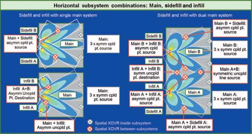
FIGURE 9.1
Typical horizontal relationships between main, sidefill, and infill subsystems.

FIGURE 9.2
Typical horizontal relationships between main, frontfill, and delay subsystems.

FIGURE 9.3
Typical vertical relationships between main, frontfill, and delay subsystems.
mains to plug the gaps in coverage. There are some shapes that will require multiple mains that in turn will be joined together as uncoupled arrays.
Multiple mains are found when the room geometry or other physical factors favor an approach beyond a single source point. The arrays must be of roughly equal rank in terms of power capability and length of throw to be considered multiple mains rather than a main and a fill system. These systems are most often seen in dual monaural horizontal arrangements where main systems are deployed flanking the stage. Such configurations differ from stereo in that the same signal is sent to both systems. This overall combined configuration is an uncoupled line source array, although it may be made up of a pair of coupled point source arrays.
The multiple main strategy is also often employed in the vertical plane, where upper and lower systems cover roughly equidistant areas. This configuration is fairly common in venues where over- and under-balcony seating areas are roughly equidistant from the speakers. These two configurations can be found together, thereby creating a four-element multiple main system with two horizontal and vertical elements.
Another four- (or more) element multiple main system is found when the horizontal “in the round” configuration is used (the vertical version requires zero gravity conditions and is much less popular). The listening area is sliced into coverage sections of roughly equal throw length for each main system. The overall combined array is an uncoupled point source. A typical example of this would be arena scoreboard systems.
There is no limit to the number of multiple mains. If the venue shape requires lateral extensions with equidistant throw length, the number of mains can rise sharply. An example of this is a parade route, where the audience distance remains constant. The overall configuration is an uncoupled line source (on the straight areas) and uncoupled point sources and point destinations on the curves. Another example is found in racetracks and sports stadiums where the systems are located on the roof overhangs.
Perspectives: The most important factor in optimization is the speaker placement. The mounting of the speaker is 80% but is thought of as only 20%. Naturally, this is best done in the system plan before it enters the site.
Kazuyuki Kado, AST Inc.
Sidefill
Sidefill subsystems provide horizontal radial extension to the main system. Sidefill systems may be directly coupled to the main system or uncoupled single elements or arrays. The typical sidefill system is an asymmetric component of the coupled point source in the horizontal plane. The common factor is that they have a significantly shorter throw distance than the mains, and therefore qualify as subsystems. The sidefill system will be assumed to be semi-isolated from the mains, with the degree of independence being inversely proportional to frequency.
Infill
Infill subsystems also provide horizontal radial extension to the main system(s). These differ from sidefills in that they are oriented toward the center rather than the outside. The infill systems form a symmetric point destination along the room center line. Infill coverage must be restricted to very limited areas in their separate local areas. The intersection of a center downfill with a pair of infills is a 3-D point destination array in the center seating area. This configuration is a mistake few designers make more than once.
Downfill
The role of the downfill array is as a vertical radial extension of the main array. The typical downfill system is an asymmetric component of the coupled point source. It can be unmatched in any or all of the categories of speaker order, splay angle, and level.
Frontfill
The role of the frontfill system is coverage of the seats very near to the stage. The speakers are usually located on the stage lip, either mounted into or laying on the stage. The array configuration is the uncoupled line or point source depending upon the geometry of the stage. These seats could alternatively be covered with fewer sources by downfill speakers from above or infill speakers from the sides. The frontfills join a flying main system as an uncoupled asymmetric point destination array in the vertical plane. They connect to an infill array as an uncoupled asymmetric point destination in the horizontal plane.
Advantages of the frontfill array:
1. Minimum horizontal and vertical image distortion
2. Minimum level, spectral and ripple variance
3. Minimum loss of gain before feedback
4. Minimum overlap into other subsystems.
The frontfill array is very limited in forward coverage depth as was discussed in Chapter 6.
Delays
Delay systems are forward extensions of the mains. Delay speakers are inherently uncoupled from the mains and combine as an asymmetric point destination array. The delay speaker may operate singly or as its own array. The most favorable array configuration is that which places the elements along an equidistant arc from the main speaker (an uncoupled point source array). This is not always practical due to the restrictions in available placement options. Another complication arises in the case of placing delays for a left/right dual mono or stereo system. In such cases, there are two conflicting concentric lines and no single solution.
BALCONY BATTLES
I don't like to admit defeat, but as the old saying goes, “It is better to run away and live to fight another day.” There is one standard room shape for which there is often no single point solution: the “W.” The “W” turned on its side is the shape that our system sees when faced with a deep balcony overhang. If we place the speakers high above, the lower area suffers from path obstruction. We must shoot through the people in the front of the balcony to try to cover as much of the rear floor rear area as we can see. It we place them low, we must shoot through the faces of the people in the lower balcony to get to the back. If we start from the middle, we face a geometric puzzle that might require M. C. Escher to do our drawings. And once again the people at the balcony front take the full frontal assault.
It should not be surprising that this geometric double take would be the Waterloo of the coupled point source. The shape is a pair of vertically stacked right triangles. We know the shapes of minimum variance and there are none that allow the sound to throw deep, go short and then repeat. Such a shape can only be done by an uncoupled pair of asymmetric coupled point sources.
The insurmountable obstacle is not the HF range. Even a relatively small amount of angular isolation will provide the beam steering needed to split the HF above and below the balcony front. It is the mid-range and below, intractably stuck in the center, that sends it crashing on to the front of the balcony.
There are three players in the balcony battle: mains, over-balcony delays, and underbalcony delays. The mains may be a single point or multiple main configuration. The question before us is to determine which combination of these will be the most effective. The first determination will usually be the mains, since the role of the others will be to supplement those areas not optimally covered by the mains. As we will see, however, the role of the fills may play a part in determining which of the mains scenarios will work best. There is a symbiotic relationship here. These would be the typical tradeoffs when facing a substantial balcony:
■ Single main: best for minimum ripple variance, worst for level and spectral variance.
■ Multiple main: worst for ripple variance, best for minimum level and spectral variance.
The extent of the differences can be evaluated by rating the balcony in dB. This is done by observing the range ratios. Notice first that we will need two proximity ratio calculations: back to front upstairs (over the balcony) and back to front (under the balcony). It is this dual proximity that is the source of all the trouble, of course, since the coupled array is not capable of doubling back its response over its full frequency range. We are far, then near, then far again, then near again. The key to this evaluation is the amount of “comeback” required, which we will quantify as the return ratio. If this is too high, then splitting the array is indicated. Figures 9.4 and 9.5 illustrate some of the considerations involved in this decision.
The return ratio is the number of dB closer we find the front of the balcony to the farthest area angularly adjacent to it. Where does the sound go when it skims just above, or below, the balcony front? If it has to go twice as far, we will have a 6 dB proximity challenge to overcome in a degree or two of angular change. The position of the main cluster will change the return ratio for a given shape. Mains positions above the balcony will use the balcony front and the last floor level seating with visual contact to the mains. Mains positions below the balcony will use the balcony front and the last upper level seating with visual contact to the mains. If the mains are centered at the level of the balcony we will use the balcony front and the last upper or lower level seat, whichever is farthest.
How much return ratio is acceptable is a question of tradeoffs. Obviously 6 dB is the limit of our maximum acceptable variance. The tradeoffs may be a host of practical matters as well as sound image and variance. In any case, it is important to be realistic about the fact that we can make only very slight returns on a coupled cluster. There are various methods out there to attempt this, such as “balcony bars” that provide some additional spacing or unplugging some of the elements in the array that are facing the balcony front. There is
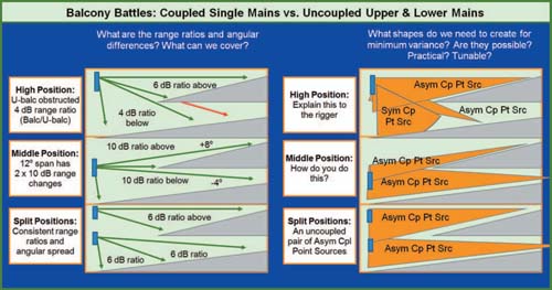
FIGURE 9.4
Balcony battles. Questions in the consideration of single or split mains.
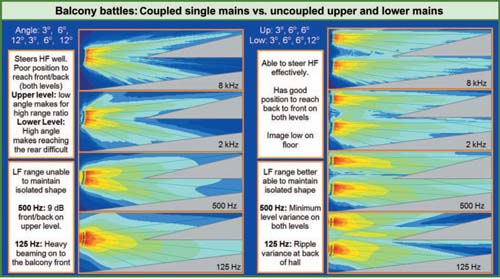
FIGURE 9.5
Balcony battles. Example application of single and split mains.
no arguing with the fact that a speaker facing directly into balcony fascia should be turned off if other speakers can still get the coverage where we need it. This is, however, a very poor solution in most cases. The other options are tapering the angles and levels down and then trying to put the genie back in the bottle by closing the angles and raising the levels. This will take care of the very high frequencies but the MF and LF range will not likely cooperate.
Here is where the fill speakers come in. First, we need to evaluate when it is that fills are mandatory. This is far more likely in the single mains scenario, since line of sound to the speakers will be cut off in many instances. The split mains should have clear lines of sound to all locations. The fill speakers have the ability to rescue the single mains by virtue of reducing the coverage range. Over-balcony speakers will reduce the upper range, which may allow a lower mains position with a better return ratio. Likewise underbalcony speakers will allow a central position to reach the distant upper areas without the need to return to pick up distant lower areas. The combination of both will ease the burden further and increase the probability of a successful single coupled mains. This has its price, however: TANSTAAFL.
The virtues of low ripple variance in the single mains must be weighed against the high ripple variance likely from the interaction of uncoupled under- and over-balcony systems. The split mains has one uncoupled spatial crossover. If the cost of keeping the mains in one piece is two vertical uncoupled crossovers and piles of uncoupled crossovers in the horizontal, the deal does not look so sweet.
Delay system considerations:
1. Do we need delays at all?
2. Will the delays improve or degrade the coherence?
3. Will the delays improve or degrade the imaging?
The question of need arises from the shape of the under (or over)-balcony space. It is not a simple matter of depth. For instance, we cannot simply say that we need delays if the underbalcony is 20 m deep. This is not the case if it is also 20 m tall! Once again enter the aspect ratio. The depth to height ratio will be a key but not a solitary factor. As the aspect ratio rises, the probability that we will need delays goes up, but there are additional factors.
A big piece of the balcony battle is doubling distance. Distant sources (like our mains) reflect off the same room surfaces as the local source (our under-balcony rescue team). The difference is doubling distance. The round trip from the back wall is a small proportion of additional distance as seen by the main system. The milliseconds add up, but the level loss is minimal, a troublesome combination. The perspective of the delay speaker would see the same number of milliseconds to take a round trip via the back wall but sees that as a much larger proportion of its path length. Once again level changes as a ratio while time changes as a difference. The result is that the reflections from the mains are much stronger than we would find from the delays, even though they are hitting the same surfaces. Therefore, we need to factor in two aspect ratios: the mains to the back wall, and the under-balcony speaker to the back wall. Both would use the same height (the under-balcony height). As the difference in the two aspect ratios rises, the need for delays increases. So the same shape of under-balcony would have a higher need for delays the farther away it gets from the mains. This is not because of the direct sound loss. It is because of the lack of loss in the reflected sound. There is often a misconception that the under-balcony area has the HF range rolled off. So long as the line of sound is clear this is not the case. What we have instead is pink shift due to LF addition because the reflections are strong. A third factor is the absorption (or lack thereof) of the underbalcony surfaces. Predictably, as absorption decreases our need for delays increases.
Now on to the question of whether the delays can help or not. It will do us no good to call the rescue team if they are not able to improve the situation. There is more to this than first appears. TANSAAFL. Delays are uncoupled arrays and there is no guarantee that their interaction with each other will not create as much ripple variance as that which they are trying to suppress. The potential for this increases when the delay speakers are too far forward of the position where they are needed, are spaced too closely, or have nearby reflective surfaces that degrade the signal. If the positions we are allowed to use are too distant, the mains will do better without any help from the delays.
SCALABLE DESIGN
Scaling for power
This would be the place to go through a series of calculations based on speaker sensitivity, maximum SPL, coupling, quantity, etc. Then we would compare the numbers with expectations of program material and the prorated distance loss less some expectation of speaker/room summation. But this is not how it's done by me, or any others that I know. There are a number of reasons for this. The first is that the SPL specifications from manufacturers are so convoluted and conditional that model-to-model comparison based on spec sheets alone is a very iffy process. The next is that the behavior of arrays is complex and interdependent, and the combined SPL is highly variable over frequency. The dB SPL ratings provide a classification for speaker elements, but the relevance to combined arrays is so fraught with variable conditions that its use is limited. A simple point here: comparison of dB SPL of two items with matched frequency response, such as two individual elements, tells us something concrete. Comparison of unmatched elements does not. For example: let's compare a three-element point source array to the center speaker alone. How do we compare the pink-shifted spectrum of three combined elements to the flat original? The LF rises on the center axis but the HF does not. In the on-axis area of the outer elements, both the LF and the HF rise. If the SPL of the array is characterized only for its on-axis response, the numbers seem disappointing. Meanwhile, the side listening areas went from darkness to light.
It seems to me that most people approach system power capability with tangible personal experience based on their experience of real devices, rather than spec sheets. We know that this venue will require a certain scale of speaker element and quantity.
I call this the Goldilocks sound design approach, and use it myself: Papa Bear, Mama Bear, and Baby Bear. The sound design is approached by first defining the power scale of the largest and longest throw system as the Papa Bear. The smaller systems are scaled from there by evaluation of the relative distances involved. If the downfills only need to go half the distance of the mains they can be scaled down by 6 dB. If the under-balcony systems go 25% of the way, then 12 dB down in dB SPL scaling will be appropriate.
It would be a waste of time for me to preach to anyone what is the right dB SPL for pop music or a house of worship. Who would follow it? We know the products we know, and that begins the scaling process. I realize that this sounds terribly unscientific but this is a time for realism. No serious professional is going to specify a main array full of elements they have never heard, based on specifications posted here or by the manufacturer.
This is one of the most important decisions about the sound system design, but the answer will not be found in a book. There is no substitute for real field experience. Our experience of sound power requires a personal encounter. We can specify cable from a piece of paper. Speakers must be heard.
Perspectives: Dialing in a system is like breaking in a new ride. A driver can affect how the performance of a new machine will finally settle in. So many factors affect large-system calibration that buyers/ users need to be thinking in terms of months or years, not weeks. Some professionals with professional equipment can certainly get it way down the track in a power burst of several days. However, after that, when people are in the room, and new resonances show up in the structure, and the actual operating volume falls into the pocket, and real noise floors are present, then it's time to get tweaky. Let the compromises begin! There is nothing like having relationships with other professionals, protest gear, freedom to experiment, and the trust of leadership, all affecting the final outcome toward excellence.
Chris Gille, Jeff Pelletier Willow Creek Community Church
Evaluating the scale factor:
■ What is the power scale required to do the job with minimal overlap between the elements?
■ What is the power scale required to do the job with larger amounts of overlap between the elements?
Naturally the latter of these can be done with elements of a smaller power scale, but we may pay a price in variance. In any case, once the main system power scale is defined, the rest will follow by relative range scaling. We will consider the matter of power scaling closed then. Everything that follows from here will reflect on power scaling only in relative terms.
Overlapping for power
Major power addition is available to us in the form of overlapped patterns. The power will not come for free as we will likely have to pay with ripple variance. Is there a best way or is this a case of “by any means necessary”? There are very clear-cut choices here. The answer lies in the beamwidth and speaker order. The plateau area of the beamwidth response is the most expensive (in ripple variance) form of overlap. The first-order speaker is the worst candidate for overlap. And every effort should be made to minimize this. The second-order speaker will typically have a smaller plateau and this gives us more room, but the ripple variance cost is still high. The third-order speaker is the easy winner here. In fact, the third-order speaker needs overlap to expand its coverage beyond a minimal area. An overlapping coupled point source comprising constant slope beamwidth elements has a fixed angular offset that creates a variable overlap percentage over frequency. As frequency falls the overlap percentage rises. The rising overlap is met by expanding wavelength, which keeps the ripple variance under control. It is a delicate dance, but as long as the displacement is kept small, the opportunity is presented for large-scale power addition, which increases as frequency falls.
Scaling the shape
Perspectives: It's not a lightical, it's a musical.
Martin Carillo
We have studied the shapes that can be created by speakers to fill the room with minimum variance coverage. The coverage shapes are scalable to the size of the venue. If the coverage shape calls for an asymmetric point source, the array must have the appropriate power scaling for the application. For a given program material, the power needs rise with the venue size. For a given venue size, the power needs rise or fall with the program material requirements. The shape to be created is the same. The larger-scale version will use higher power, higher-order elements, and contain greater amounts of overlap. The smaller-scale and lower-power systems will use fewer elements, lower speaker orders, and less overlap to create the same basic shape.
The scalable design is used to fill a comparable space. We can fill 90° of symmetric coverage with a single first-order speaker or 90 third-order systems splayed 1° apart. The shape is comparable but the power could be orders of magnitude apart, as would be the budget, the rigging requirements, the ripple variance, and a host of other tradeoffs. The final decision will rest on the best compromise.
All of the array shapes shown in the minimum variance menu are scalable. The coupled arrays can be filled with varying quantities and percentage overlap. The combination of one array with another is simply a second generation built upon the previous. Coupled arrays at different locations will combine as uncoupled arrays in the big picture. This is more of our scalable paradigm.
ARRAY DESIGN PROCEDURES
Main system design
If a single speaker will suffice, there is nothing more required here than to follow the single-element guidelines for symmetric and asymmetric aiming. The coverage pattern is determined by the aspect ratio.
If such a scheme is not satisfactory we will resort to a coupled point source of the symmetric or asymmetric type. There are two versions of each we will consider: minimum variance (with maximum power) and maximum power (with minimum variance). The difference between the two approaches is one single parameter: angular overlap.
Primary reasons to choose the coupled point source:
1. Radial extension beyond the capability of a single unit
2. Radial edge definition beyond the capability of a single unit
3. Power addition through radial overlap.
Once we cross the line to the coupled point source we must abandon the simplicity of the aspect ratio for the radial arc. There is no “correct” element with which to start the coupled point source. We must start with something and then the process begins as we see what is left to cover. After the next piece is added we re-evaluate again until the shape is filled. The process can be restarted until a satisfactory assemblage of puzzle pieces is found.
Let's begin with the symmetric version.
Symmetric coupled point source
There are two modes of overlap behavior that characterize the symmetric point source array over quantity (Fig. 9.6). When the overlap approaches 100% the combined coverage angle is found by FAR multiplication. This provides the maximum on-axis power addition as well. At the opposite extreme, unity splay (0% overlap) is characterized as splay angle multiplication (or coverage angle since they are the same). This has the least on-axis power addition, but we should not forget that we are spreading power addition across
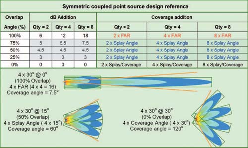
FIGURE 9.6
Design reference for the symmetric coupled point source.
the arc. The middle ground behavior is the partial overlap configuration, which is characterized as splay angle multiplication (which now differs from the coverage angle). This is the middle ground in on-axis power as well.
How angular overlap affects combined coverage angle:
1. 0% overlap: Combined coverage = Quantity × the splay angle (or element coverage angle)
2. 5–95% overlap: Combined coverage = Quantity × the splay angle between the elements
3. 100% overlap: Combined coverage = Quantity × the forward aspect ratio.
Let's say we measure the coverage area and we need 40° of coverage. What are our options? There are countless ways to create a symmetric 40° coverage pattern. The following example illustrates the role of overlap in the computation of combined coverage angle.
Combined coverage angle of 401:
■ 1 × 401 speaker (FAR 3)
■ 2 × 201 speaker @ 0% overlap (coverage of 20° × 2 = 401)
■ 2 × 271 speaker @ 25% overlap (splay of 20° × 2 = 401)
■ 2 × 401 speaker @ 50% overlap (splay of 20° × 2 = 401)
■ 4 × 401 speaker @ 75% overlap (splay of 10° × 4 = 401)
■ 8 × 201 speaker @ 75% overlap (splay of 5° × 8 = 401)
■ 2 × 801 speaker @ 100% overlap (FAR 1.5 + FAR 1.5 = 3).
All of the above scenarios have compromise considerations. Overlap is never free of ripple variance. There is always a tradeoff of power and ripple. As overlap increases, the key to minimum ripple variance is low displacement. The third-order speaker is our best choice in high overlap designs. Low overlap designs favor the first- and second-order beamwidth plateau with its extended isolation zone.
Symmetric coupled point source design procedure:
1. Define the coverage shape as an arc from the speaker array location.
2. Select an element with an aspect ratio that will fit inside the shape.
3. Place additional elements at the unity splay angle to provide radial extension until the shape is filled. The combined coverage angle equals the individual coverage angle multiplied by the quantity (Fig. 9.7).
If more power addition is required, then reduce the splay angle to less than unity and add units until the shape is filled. The combined coverage angle equals the splay angle multiplied by the quantity.
Asymmetric coupled point source
The asymmetric coupled point source is chosen for the same reasons as the symmetric point source but fits into a different shape. The power addition of the asymmetric point source is self-scaling since the entire rationale for this array is how it fits into a variable distance shape. The levels are tapered as appropriate to scale the array to the distances presented. If low overlap is desired, the unity splay angle must be compensated as appropriate for the level offset factor.
There is no “correct” element with which to start the asymmetric coupled point source. We must start with something and then begin the process to see what is left to cover.
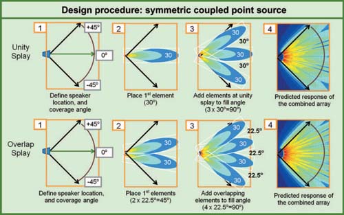
FIGURE 9.7
Design procedure for the symmetric coupled point source.
After the next piece is added we re-evaluate again until the shape is filled. The process can be restarted until a satisfactory assemblage of puzzle pieces is found.
It is a simple matter to find the unity splay in a symmetric array. A pair of 301 speakers will be splayed 301 apart. The equation is the symmetric unity splay equation:
*when levels are matched.
Therefore,
The spatial crossover would be at the geometric and level midpoint: 151 off-axis to either element. What if we want to merge a 30° and 60° speaker? The same equation applies, as long as the levels are matched:
FIGURE 9.8
Design reference for the asymmetric coupled point source. The computations for a 901 combined coverage angle are shown. Other angles can be substituted and prorated by the same percentage rates.
With a 45° splay, the elements will meet at the same spatial crossover point: 15° off-axis from the 30° element. It would be met there by the −6 dB edge of the wider element, 30° off-axis to its center. The spatial crossover is the level center, but not the geometric center.
The equation must be modified if the levels are offset between the elements (Fig. 9.8). There is no best splay angle between two speakers, until we know the distance/level relationship. If we were to take two matched elements and turn one down 6 dB, the supposed unity splay angle will not provide unity results. The geometric center will find −6 dB from one element and −12 dB from the other. What is the unity splay angle then? A change of 6 dB is a 50% level change. The splay angle must be adjusted by the same ratio to bring back unity performance through the spatial crossover. A 6 dB reduction shrinks the range of the speaker in half. That will be the decisive number.
The compensated unity splay equation:
*assumes that levels are set in proportion to the distance.
Here is an example of two 301 speakers with one covering half the distance of the other (−6 dB):
Here is an example of a 301 speaker joined with a 601 element that is covering 70% of the range of the other (−3 dB):
FIGURE 9.9
Design procedure for the asymmetric coupled point source.

Asymmetric coupled point source design procedure:
1. Define the coverage shape and speaker location (Fig. 9.9).
2. Select the first element and aim it at the most distant location within the shape. This element will have the narrowest coverage angle.
3. The next step is to define the distance at which the transition into the next element is expected to occur (the on-axis location of the next element). For example, the first element is 30°, draw a line 30° off-axis and define the range. If this distance is less than the first element, then a compensated unity splay angle will be required.
4. Select an additional element. The combined coverage of the two elements is used to calculate the symmetric unity splay angle. The level offset provides the compensation percentage.
5. Position the second speaker at the compensated angle and appropriately scaled range. If the coverage angle or range difference between the elements is very large it may be necessary to adjust the compensation. This is done by reassessing the range ratio and adjusting the compensation until the best fit is found.
6. If power addition is required, then reduce the splay angle to less than unity and add units until the shape is filled.
7. Continue the process with the third element being aligned to the second element and so forth.

FIGURE 9.10
Design examples for the asymmetric coupled point source. In each case, the outer elements are designed with compensated unity angles that customize the combined shape to conform to the listening area shape.
Recall Fig. 6.10, where we saw that the details in the building shape had only a minimal effect on the single speaker solutions. The upgrade to a coupled array opens up a huge variety of possibilities available to customize our array to the room shape (Figs 9.10–9.14).
Asymmetric-composite coupled point source
An asymmetric-coupled point source can be constructed in a modular form from pre-combined symmetric coupled point sources. This is the means by which manageable high-power arrays can be designed with substantial overlap. The distance/level layering principles of the asymmetric coupled point source provide the outer structure, which combines highly overlapped symmetric subsystems. The elements in this case must be third-order systems, which are well suited for the task.
The composite array provides a practical and definable character to the 16-element, 11-different angle, 3-different level line array that is the current mainstay of the industry. Let's take a moment and consider the situation, since this is indeed the most popular type of main system array. At the end of the day we are going to need to tune it. How? If we see a response we don't like at some location, what speaker or channel are we going to adjust? What parameter: angle, level, EQ, or delay? If we can't single out responsibility for the problem, we can only guess at a solution. The design must incorporate a plan all the way to final calibration before it ever goes to bid. The calibration process relies on the knowledge of what speaker is in charge of every area in the room. The system needs a “chain of custody” as we move through the hall. Therein lies the hope of adjusting the subsystems to fit into the complex target shape. If the 14th row has a problem, we need to know who to call.
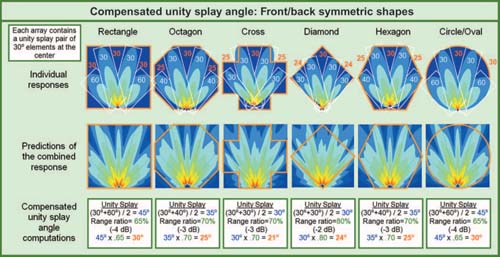
FIGURE 9.11
Design examples for the asymmetric coupled point source. In each case, the inner elements are designed with symmetric unity splay angles while the outer elements are designed with compensated unity splay angles that customize the combined shape to conform to the listening area shape.
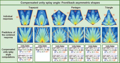
FIGURE 9.12
Design examples for the asymmetric coupled point source. In each case, the shapes are front/back asymmetric. The outer elements are designed with compensated unity splay angles that customize the combined shape to conform to the listening area shape.
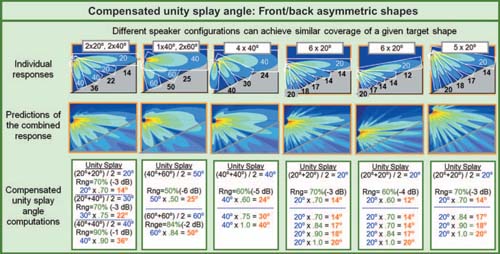
FIGURE 9.13
Design examples for the asymmetric coupled point source, typical of vertical applications. In each case, the same shape is presented for coverage. Different combinations of elements all create a minimum variance coverage of the shape.
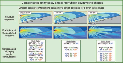
FIGURE 9.14
Design examples for the asymmetric coupled point source, typical of vertical applications. In each case, the same shape is presented for coverage. Different combinations of elements and positions all create a minimum variance coverage of the shape.
Through the course of this and the previous chapter we have established the individual shape of the loudspeaker and seen how we make combined shapes from these elements. As long as we have some isolation (angular or distance), we can establish a dominant speaker for a given area and locate the handoff points in the chain of custody: the crossovers. This is simple and clear when the overlap is strong and widespread, such as with unity splay first-order systems. Yet even these systems share 100 Hz with virtually every other speaker in the hall. It is given, then, that our ability to single out responsibility falls gradually with frequency. At the opposite extreme, we have the hyperoverlapped third-order systems where every frequency is a shared resource. Is there any hope to single out the effect of the individuals among 16, 24, or 32 overlapped boxes? Yes. And we can design it to be tuned as easily as we would a three- to four-box array.
On our way to this conclusion let's consider how these arrays are typically designed in the modern age:
1. Select the element based on power class and budget
2. Divide the budget by the number of elements
3. Play with every iteration of angles until the best fit is found.
If you're feeling insulted at the moment, please forgive me. This was my design process until I found a better way. I have run mics in a line from top to bottom of these types of arrays searching for ways to enact optimization solutions. Without defined zones, the optimization process is little more than the same kind of iterative guesswork that began in the design process. Even the experience of having tuned hundreds of asymmetric coupled point source arrays was no match for the complex overlapping interactions found here. Much is made in the industry of how line arrays act as a single speaker. What does a single speaker look like? Would you be surprised if the center of your single speaker at 8 kHz was 16° above the center at 125 Hz? How about one where the loudest point at 8 kHz is off-axis at 125 Hz? That would be one strange speaker! You can find it back at Fig. 7.33(a). There is no single speaker in the world that has this form of rampant asymmetry that creates a different on-axis beam at every frequency. That is the destiny of coupled line arrays implemented with a host of different angles on adjacent elements and driven by a single processing channel. Even if we were to define it as a single speaker, we cannot hope to calibrate it as a single speaker. Calibration requires a defined beginning, end, and (most importantly) center of its coverage pattern. The center of a multi-element asymmetric array is inherently unstable over frequency. The coverage pattern of an individual element is not stable over frequency, leaving us with a variable percentage of overlap over frequency. The isolated highs may spread on the diagonal but the lows are certain to concentrate toward the middle. The mid-range is pulled in both directions. None of them agree on the center. Without a defined center the process of optimization has lost its primary base of operations. How can we define “off-axis” if we can't find “on-axis”? Without a center, we will not be able to ascertain a nominal level setting, or an equalization that represents the middle ground of the coverage segment. In short, our hopes for a definable center point lie in symmetry, without which we are left with optimization based on an arbitrary mic placement.
The use of a single processing channel would be logical, provided all elements on that channel are symmetrically arrayed. If they are not, the symmetric solutions enacted by the signal processor will not have the expected results.
Does this mean we need 16 different processing channels to drive a 16-element array? Not likely. What building could possibly have a shape that would require 15 different splay angles and/or level adjustments between our cabinets? How can we make a 16-element cluster into a manageable, predictable array? Break it into sections of symmetric coupled point source arrays. Each has a top, middle, and a bottom. We have center on-axis areas for position adjustment, level setting, and equalization. We even have a defined spatial crossover. The segments will be designed to take on the character of a single speaker, which they can much more closely assume, due to their symmetry. The “composite speakers” that comprise our asymmetric coupled point source would mimic the characteristics of a comparable array of single elements: the longest throw goes to the narrowest speaker at the highest drive level, and down we go. How many subsystem breaks should there be? This is a practical as well as architectural issue. Asymmetry in the required coverage shape will need to be met with complementary asymmetry in the array, but we cannot expect the system to conform to small shape variations in the room. Each subsection will need to be individually aligned and woven together with the others during the calibration stage. In most cases, three or four subsections should get the job done.
The design process for the composite array flows in similar fashion to our previous efforts with individual elements. Define the longest section and subdivide the remainder. The biggest difference is that the segments are arc sections (since they comprise overlapped elements). Arc sections combine differently than the rectangular shapes of the single elements. There is no unity splay angle compensation process because we are highly overlapped (not unity to start with). The spatial crossover is so highly overlapped and minimally displaced that there will be no effort made to phase-align in the crossover area. Just as we used the on-axis point of the individual elements as a level setting point, we will do the same with the center point of each composite segment.
Before we move on, let's take a moment to address the issue of level segmentation. There is much talk about how much level tapering is healthy or proper for the system, and how large the incremental changes should be between adjacent cabinets. The argument that all speakers need to be turned up “to 11” is as old as the hills. It dates back to the wall of sound days and is immortalized in the movie, This is Spinal Tap. This mentality holds that turning down some elements will deprive the system of its vital power, the unspoken remainder of the sentence being “at the mix position.” The reality is, that depriving your system of level tapering overpowers the front areas and oversteers the beam concentration so that patrons in the upper and lower portions are out of the low mid-range pattern (while still getting the high mids and highs as in the right panel of Fig. 7.33(a)). When a uniform experience is desired, the SPL Preservation Society will need to back off and let us taper the level in accordance with the hall geometry. If this is not enough power, then get a bigger system so that all audience members get a share of the action. As for incremental taper size, the answer is simple. Look at the proximity ratio from top to bottom. Whatever we don't get from overlapped power concentration we will need to make up with level tapering. The increments can be few and large, or many and small. The only rule is that whatever is driven by one channel is a symmetric defined subsystem.
The amount of level tapering required for the composite systems is less than we would use for isolated single speakers. The reason is the differences in coupling addition inside each composite element. Three elements at 1° will have more coupling than three at 2° and so on. If we only consider the distances where each composite element lands we might conclude we need 6 dB of level tapering. When the greater coupling addition of the narrow element is factored in, the actual required level offset may be much less. This tradeoff is termed coupling compensation: the difference between the expected levels by inverse square law and those found with differing amounts of overlap coupling. Various configurations of the composite coupled point source are shown in Figs 9.15–9.18. Range ratio compensation is included here, with a good example being the right side of Fig. 9.16 where the expected taper would be 12 dB but turns out to be just 6 dB after compensation.
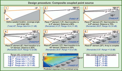
FIGURE 9.15
Design reference for the symmetric uncoupled line source.
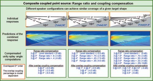
FIGURE 9.16
Design examples for the asymmetric-composite coupled point source, typical of vertical applications. In each case, the same shape is presented for coverage. Different combinations of elements create a minimum variance coverage of the shape.
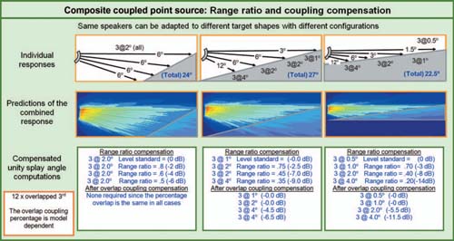
FIGURE 9.17
Design examples for the asymmetric-composite coupled point source, typical of vertical applications. In each case, a different shape is presented for coverage. Different combinations of elements adapt the coverage to provide minimum variance coverage of the shape.
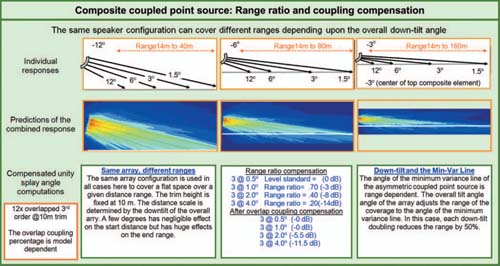
FIGURE 9.18
Design examples for the asymmetric-composite coupled point source, typical of vertical applications. In each case, a different range of maximum distance is presented for coverage. The same array settings are used in all cases, with the overall down-tilt angle serving as the range adjustment mechanism to provide minimum variance coverage of the shape.
Principles of the asymmetric-composite coupled point source:
1. Symmetric subsystems are designed to create a defined combined coverage angle. This is typically highly overlapped, so the coverage angle will be the quantity of elements × the splay angle.
2. The center line of each symmetric subsystem provides the distance offset parameter for level setting.
3. The number of asymmetric layers and the division between the layers can be modified until the best fit for the shape is achieved.
Asymmetric-composite coupled point source design procedure:
1. Define the coverage shape and speaker location (Figs 9.15–9.18).
2. Select the most distant location, which is now defined as the coverage top (the vertical plane is assumed).
3. Select a lower limit that subdivides the coverage shape. The angle between the upper and lower limit will be the area covered by the first symmetric subsystem. This symmetric subsystem will have the narrowest coverage angle and should have the highest percentage of overlap between the elements. The distance from the source to the center of this coverage arc is the level-setting distance.
4. Fill the selected arc angle with a sufficient number of overlapping elements whose combined splay angle equals the designated arc angle.
5. Subdivide the remaining space with a second arc segment, and repeat the process. The distance/level scalar is found at the center of each arc. The number of subdivisions is optional.
6. Repeat the process, each time decreasing the overlap percentage until the coverage shape is filled.
Symmetric uncoupled line source
This is used for multiple mains and a variety of auxiliary systems such as frontfill, under-balcony, etc. This is a range-limited system.
Symmetric uncoupled line source design procedure:
1. Define the coverage shape as a line from the speaker array location (Figs 9.19 and 9.20).
2. Define the line length and the minimum and maximum desired range.
3. Select an element and place it in the central area of the line.
4. Define the coverage by the aspect ratio method. The maximum range is the length.
5. The element-to-element spacing is found by stacking the aspect ratio rectangles along the line.
6. Place additional elements until the line length is filled.
7. Evaluate the minimum range of coverage for gaps. If the gaps are too large, the maximum range will need to be reduced and the element spacing reduced. Alternative option is to use wider elements (This reduces the maximum range).
8. The maximum range is limited by the three-element overlap point, which is a function of the aspect ratio and the spacing. Consult the uncoupled array spacing reference (Fig. 9.19) for the applicable values.
Asymmetric uncoupled line source
This is used for multiple mains and a variety of auxiliary systems such as frontfill, under-balcony, etc. This is a range-limited system.
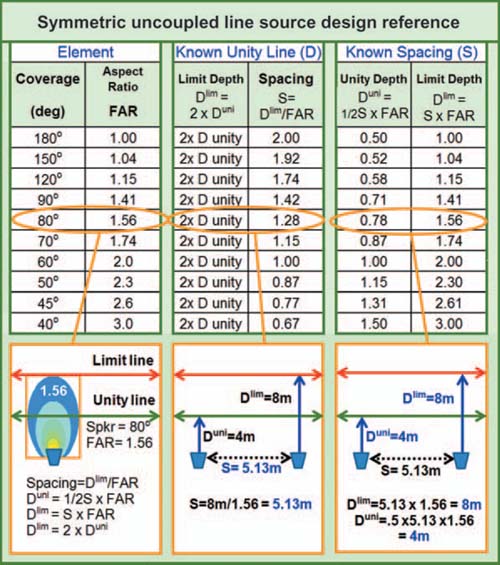
FIGURE 9.19
Design reference for the symmetric uncoupled line source.
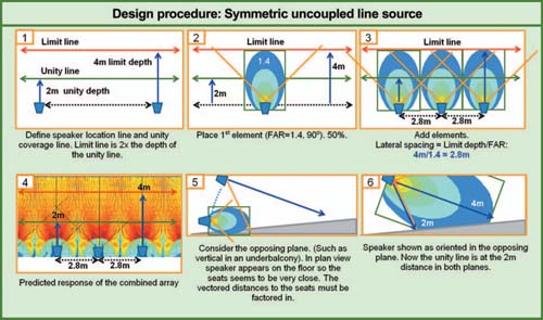
FIGURE 9.20
Design procedure for the symmetric uncoupled line source.
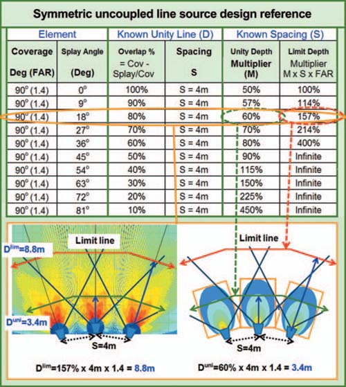
FIGURE 9.21
Design reference for the symmetric uncoupled point source.
Asymmetric uncoupled line source design procedure:
1. Define the coverage shape as a curved line.
2. Define the maximum range for the element with the longest throw. If different models of speakers are being used, this should be the highest order element.
3. Select an element and place it with its aspect ratio scaled to the throw distance.
4. Place the next element and scale the length as appropriate for the given distance. The relative spacing and speaker order will determine the amount of overlap. A unity spatial crossover will require a compensated spacing/level/speaker order relationship.
5. Determine the relative distance range required of the second element (as compared to the first) and scale the power capability as appropriate.
6. Continue with each additional element having compensated spatial crossovers to the neighboring element until the desired shape is achieved. Shorter-range elements may be power scaled as appropriate.
Symmetric uncoupled point source
Symmetric uncoupled point source design procedure:
1. Define the coverage shape as a limited range arc (Figs 9.21 and 9.22).
2. Define the arc radius, length, and the minimum and maximum desired range.
3. Select an element and place it in the central area of the arc.
4. The maximum range is limited by the three-element overlap point, which is a function of the aspect ratio, the angular offset, and the spacing. Consult the uncoupled array spacing reference (Fig. 9.21) for the applicable values.
5. Place additional elements until the arc is filled.
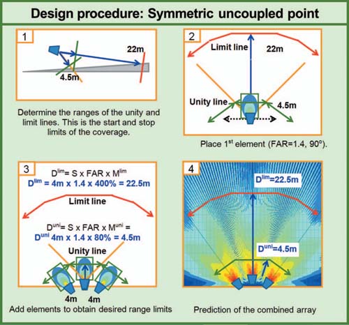
FIGURE 9.22
Design procedure for the symmetric uncoupled point source.
Asymmetric uncoupled point source
Asymmetric uncoupled point source design procedure:
1. Define the coverage shape as an asymmetric arc (a portion of an ellipse rather than a circle).
2. Define the maximum range for the element with the longest throw. If different models of speakers are being used, this should be the highest order element.
3. Select an element and place it with its aspect ratio scaled to the throw distance.
4. Place the next element and scale the length as appropriate for the given distance. The relative spacing and speaker order and angular offset will determine the amount of overlap. A unity spatial crossover will require a compensated spacing/level/speaker order relationship.
5. Determine the relative distance range required of the second element (as compared to the first) and scale the power capability as appropriate.
6. Continue with each additional element having compensated spatial crossovers to the neighboring element until the desired shape is achieved. Shorter-range elements may be power scaled as appropriate.
Symmetric uncoupled point destination
It is assumed that this is a fill system (e.g., infill) being combined with a previously defined main system. The range of such systems is extremely limited and must be bordered by systems with superior means of minimum variance coverage.
Note: This is not to be confused with a stereo that consists of separate channels of information. The center-panned signals of a stereo system will, however, behave as a symmetric uncoupled point destination.
Symmetric uncoupled point destination design procedure:
1. Determine the target area of coverage extension to be provided by the fill system.
2. Orient the fill speaker for minimum variance coverage of the target area.
3. The intersection of the on-axis lines of the elements provides the forward aspect ratio scale length. The usable coverage of the array is limited to 50% of the FAR length, due to ripple variance.
Determine the relative distance range required of the fill (as compared to the mains) and scale the power capability as appropriate.
Asymmetric uncoupled point destination
Asymmetric uncoupled point destination design procedure:
1. It is assumed that this is a fill system that is being combined with a previously defined main system.
2. Determine the target area of coverage extension to be provided by the fill system.
3. Orient the fill speaker for minimum variance coverage of the target area.
Determine the relative distance range required of the fill (as compared to the mains) and scale the power capability as appropriate.
MULTICHANNEL SOUND
Much has been made here of the balancing act between concentrated power and minimum variance. As long as we continue working on the same basic assumptions, there are only incremental improvements possible as we find ways to minimize displacement in ever more powerful packages. There are, however, alternative strategies available, one in particular that has been tried long ago and mostly forgotten.
Perspectives: Know your client. I once spent one and a half days placing and aligning both main and near-field monitors in the control room of a large studio complex. The studio room was well equipped with a grand piano, a very spacious drum booth, several vocal booths, etc., and was big enough for a 60-piece orchestra. I remounted and rewired outboard equipment into lower profile racks to avoid reflections near the mix position and even time-aligned the near fields with the mains so that engineers could fade from one to the other seamlessly.
The client was amiable enough but implied that I shouldn't worry if things weren't perfect. He had a very relaxed attitude considering I was aligning a studio that clearly represented a major investment. As was my normal practice, I aligned the monitors for a wide “sweet area” and conducted listening tests using CD tracks that I knew well then, once satisfied, approached the client for a selection of secondary master tapes so that we could fine-align the system to his particular wishes.
The first track was a well-known television (TV) advertisement for frozen peas followed by one for washing powder and another for toothpaste! The client then explained that most mixes would be finalized using a typical domestic TV as a reference monitor. The main and near-field monitors would be used to check for hum, clicks, and HF crosstalk though …
Jim Cousins
The conventional high-power sound system mixes the huge number of individual input channels into just two high-pressure pipes: left and right. The sound system must reproduce the entirety of the signal presented and uses huge amounts of acoustic overlap to achieve the required SPL. Because the signal is electronically precombined, the speaker system must be able to meet the power requirements of all of the channels, all of the time. This requires a lot of headroom, which is achieved by acoustical overlap, which costs us variance. TANSTAAFL and triage again.
But who says it is mandatory to do all of the combining in electronic form? Stereo, as we know, combines in the acoustic space, as do all forms of natural sound. Why limit ourselves to two channels? Why not have separate speaker systems for the vocals, the guitars, or whatever?
The concept is the separation of the power and coverage requirements into a true multichannel system, an alternative form of isolation. We can take four channels of stage sources and combine them electronically into a highly overlapped four-speaker array. The signals are mixed electronically and summed acoustically. We could alternatively separate the four channels and send them individually to each speaker. The signals are mixed acoustically and no stable summation occurs. Is there a difference? Yes and no. The total acoustic power available is the same (the laws of thermodynamics). The power available on a per-input-channel basis is reduced, but the perceived loss in a musical context may be far less than one would assume. Have you ever considered how it is that a 50W Marshall stack can keep up with our 10kW sound system? Our sound system has to meet the power needs of the entire mixed waveform of the guitar and everybody else. If we muted every channel except the guitar, our PA will be able to blow away the Marshall stack, no problem.
Multichannel sound in the cinema is nothing new. A center vocal channel is used, along with stereo music and effects. This is done to minimize ripple variance in the voice channel, which would decrease intelligibility. We can do the same in our concert sound systems, in the form of a left, center, and right configuration. Each channel must cover its required area, which for the center system is the entire room.
We can go beyond three channels. In fact, there is no limit. We can have a complete sound system for every instrument on stage and do all of the mixing in the room, the most similar configuration possible to natural sound transmission. This has been implemented, long ago, which brings us back to the 1974 Grateful Dead concert at the Des Moines Fairgrounds that was discussed in the Preface. This sound system had completely separate sets of speakers for each string instrument, the drum set, and the vocals. The sound was mixed acoustically. Their implementation had fatal flaws, such as the minor issue of all of the speakers facing directly into the vocal mics, but the fundamental concept of multichannel separation is potentially viable.
There are a number of developments since 1974 that create a more favorable environment for multichannel mixing:
Modern multi-channel system considerations:
1. Affordable and flexible multichannel mixing consoles and signal processing.
2. Huge increases in stage source isolation that allow us access to single source channels entirely free of acoustic leakage from the other stage sources.
3. In-ear monitors providing reduced leakage from the stage in to the listening area.
4. Speaker systems that have extremely smooth, wide horizontal coverage and controlled asymmetric vertical coverage, hung with ease from one or two rigging points.
If we have 48 of the third-order speakers in the budget we have some choices ahead. We can go stereo (2 × 24) with lots of overlap. Left/Center/Right (3 × 16) with more separation and less overlap or subdivide further and further as long as we can meet our coverage needs and not fall short of the power requirements of the individual channels.
This is not something to be entered into lightly. It requires careful forethought in regard to which channels are to be mixed electronically and which are to be mixed acoustically. The key to a successful multichannel implementation is electronic isolation of the source channels and the saving of their combination for the acoustic medium. If isolation is not achieved there will be a host of unexpected summation interactions between the related signals as they arrive from the different speakers. If source isolation can be achieved the possibilities are unlimited. Not only can we have unlimited power with minimum variance, but we can also start playing with spatial movement all around the space. Now the fun begins!
There is one final consideration in regard to the multichannel paradigm: the use of multichannel mixing precludes us from being able to obtain accurate stable acoustical analysis data of the system in its performance context. If we are mixing the sound acoustically, we will not be able to compare the combined signal to an electrical reference, and therefore we will be unable to perform ongoing optimization with an analyzer during performance.
The process of measuring the sound system will now become the focus of our study.