
Production Sound III: Dealing with the Output of Microphones
Microphones are called, as a general class, transducers, changing acoustical energy, sound, into electrical energy, voltage. They typically put out much lower voltage levels than most audio gear, so they must be amplified by a microphone preamplifier to be brought up to usable levels. A typical amount of voltage delivered by a professional microphone is 13 mV (0.013 V), a rather small voltage, for 94 dB SPL, 1 a rather loud level. Thus microphones must be connected to microphone inputs as opposed to line inputs, and the converse is true, too: line-level devices such as CD players must be connected to line-level inputs and not mic inputs. If a line-level device is connected to a microphone input, the result will typically be overload or bad distortion. If a microphone is connected to a line-level input, and the gain is raised high enough to hear the signal at all, the result will typically be quite noisy or hissy. The mic/line situation is complicated by the microphone attenuate (MIC ATT) switch on some cameras that allows high-level microphone outputs (when encountering loud sound) to be accommodated by low-level (more sensitive) microphone inputs.
This chapter will give you the details needed to scale the voltage output of the microphone as needed to the input capability of the microphone preamplifier, whether in a camera or an external mixer. Before putting these steps into action, it is important to understand that over-recording digital audio is a very bad thing to do, as the onset of audible distortion is very quick when the maximum level is exceeded. On digital peak meters, the maximum recordable level without distortion is defined as 0 dBFS. Figure 6-1 shows a good recorded level for dialogue. The bar on this camera display indicates the current peak level, and the separated section indicates the recent peak level. Here, the signal is somewhat dominant in the left channel, which could indicate one of three things: (1) the sound source was off center to the left; (2) the signal was greater from the microphone plugged into the left channel input; or (3) the left channel gain was set higher than the right channel gain in using the audio level knobs on the camera. Offsetting the audio level as shown in Figure 6-1b is a common tactic when a single mic is being fed to both channels in order to provide a backup recording at a lower level in case the primary recording exceeds the available headroom on channel 1. 2 If your audio meter includes level markings, peak levels for normal dialogue should not exceed −12 dBFS, leaving 12 dB of headroom for unexpectedly loud sounds.

Figure 6-1 (a) The audio meters on most digital video cameras show left and right channel peak levels both currently (the bar) and in the recent past (the separated line sections giving “peak hold” functionality). This peak level is good for dialogue recording. (b) Levels for each channel are usually adjustable using audio gain controls on the side or back of the camera.
While in cinema at large the name Cries and Whispers normally refers to the Bergman movie of that name, in sound we can use the phrase to describe being able to record very loud sounds without distortion and very soft ones without excessive noise, at least of the electronic variety. Accomplishing this is a matter of matching the dynamic range of real life to that of the recorder.
Real life has the potential for wide dynamic range. While the span of the quietest sound you can hear to the loudest sound you can normally tolerate is about 120 dB or a ratio of one million to one, even perfect 16-bit digital recordings can produce only 93 dB range,3 and actual practical cameras set to 16-bit recording have much less range. Measuring a Panasonic AG-DVX100Ap through its microphone input to its analog audio output showed it to have 58 dB dynamic range, and from its microphone input to its FireWire (digital) output to have 69 dB range. 4 The analog Nagra 4.2 recorder used on many older feature films, measured a similar way, has a dynamic range of 72 dB. So in practice, this DV camera is a little less good than the mono Nagra that it replaces when the move is made from film to DV as an original capture medium.
Recording Level Parallels to Early Cinematography
In the early days of the cinema industry, light meters did not exist. Cinematographers learned that with a certain amount of light on a subject, a certain f-stop, frame rate, and shutter angle would produce an exposure that contained a full tonal range from black to white: the image was said to be exposed correctly. Light meters were not introduced until the late 1930s and have been in use ever since.
Certainly one of the most famous still photographs of all time, Moonrise over Hernandez by Ansel Adams, was photographed without an exposure meter: there simply was no time to take a meter reading because of the fleeting weather conditions. What Adams knew from experience was the film speed, the f-stop, and the shutter speed for the full moon, and he exposed the negative for that.
Sound people today are like cinematographers before 1935, or like Ansel Adams in 1941, without meters and in such a hurry that we have to know what we’re doing. We learn what sound levels are expected, and once we have a good feel for it, we can apply the methods of this section to help fit the real world into the recordable space—the dynamic range—on the medium. However, it does take time to learn what to expect. Table 6-1 gives some day-to-day sound levels so that you can calibrate your ear to know when you may be in trouble and have to resort to special measures. The table lists two different measurements: a type of average level called LAeq and the peak level of various sources.
Table 6-1 Sound levels encountered in various shooting situations.
dB SPL* | ||
Item |
LAeq |
Flat response, Peak detector, Impulse time response |
Quiet room suitable for recording without extra precautions |
20 |
68 |
Fairly quiet room but would require careful manipulation of background both in editing and mixing |
28 |
62 |
Apple G5 measured at user’s head, with computer on the floor below |
36 |
60 |
Fairly quiet Hollywood street, peak represents car and truck passbys; suitable for shooting at least close-ups, especially if traffic could be controlled |
48 |
65 (car by); 93 (truck by) |
Quiet model dishwasher at 1 meter (m) |
51 |
63 |
Television news listening at 3 m |
55 |
82 |
Normal speech measured at typical close boom position at 0.5 m |
65 |
86 |
Noisy Hollywood street: 7900 Sunset Blvd. at Director’s Guild of America on a Saturday afternoon, peak level caused by city bus driveby across the street |
65 |
105 |
Interior Los Angeles delicatessen at lunchtime |
70 |
104 |
Normal speech measured at lavaliere position |
75 |
95 |
Urban street including bus passing observed from bench at side of street |
82 |
107 |
Actor shouting at 0.5 m |
na |
128 |
*The reference level of 0 dB for SPL is a pressure of 20 μN/m2.
The first thing to notice about the table is that the first and second columns of data are very different. Just watching television shows a difference of some 27 dB from the average level to the peak level, a huge variation.
The LAeq method of measuring sound pressure level involves first frequency weighting—that is, modifying the frequency response rather like tone controls do, but in a specific way that better matches human perception (rolling off the bass and extreme treble because we don’t respond to them as strongly as to mid-frequency sound). This process loses some level relative to the peak because content is taken away. Second, a type of ac-to-dc converter called rms is used, progressively under-reading shorter and shorter events. This process also loses level relative to the short-term peak, because short time events slip through this relatively sluggish device. Finally, the eq part of the term means equivalent, that is, a long-term running average of the thing being measured, with excursions in level both above and below the level measured. All three of these items cause the reading to be reduced compared to the instantaneous peak, and used together, they accumulate to a very large difference.
The “flat, peak, impulse” method of measurement means no frequency weighting is employed (flat frequency response, i.e., tone controls set to neutral), the detector used captures the peak (highest) value, and the impulse time constant of 35 milliseconds (ms) is used. While we can hear distortion in as little as 2 ms and thus must leave some headroom for instances even above the level stated, 35 ms is the fastest setting on many professional sound level meters.
Note that average levels are often more widely published, but the peak level is what causes distortion problems, and so must be observed for our purposes here. Also note that the difference between the two values is not fixed: it all depends on the situation. For instance, look at the first two items; both are rooms that we could record in, but we would certainly prefer the former. Although the first is some 6 dB noisier on the flat, fast measurement, its weighted average level is 8 dB quieter! The higher peak level wasn’t even audible because the increase in noise in the quieter room was apparently at very low frequencies, where hearing is not nearly as good as in the midrange.
This is the stuff that makes people throw up their hands and say that measurements are meaningless and you can’t quantify something like hearing, but that would be wrong. We can make great use of LAeq to check the background noise level of a space, say while scouting locations, whereas we must use the faster measurement (and even leave some room above it for shorter-term events) to determine how much input level the microphone and recording system will see on peaks. The peaks require special care in handling, because they can cause distortion if over-recorded. Having a professional sound level meter available is rare, but coming to know what background levels and peak levels are like, even experientially, is useful.
Fortunately, the wide potential dynamic range of real life is not encountered often while recording many kinds of programs. Take an interview situation: it probably won’t get too loud, although having a low background noise level is important because speech in a quiet setting leaves holes in the program material: silence on the part of the talker between the syllables—or more exactly, the phonemes, which are the fundamental molecules of speech—that can reveal noise. The noise in the silences may be either the acoustical noise in the space or the hiss caused by the electronics involved in recording, and it is the latter which we can control using the methods discussed in this chapter. Acoustical noise has to be reduced by paying attention to background noise levels during selection of the site, and by utilizing the directionality, location, and aiming of the microphone.
Just the sound of an actor or documentary subject talking normally measures an average of 65 dB SPL at a conventional boom location for close-ups, but we must leave headroom for occasionally louder brief sounds, measured to be 86 dB 5 peak. 6 And getting to the instantaneous peak value so as to prevent any audible clipping probably takes this up to something over 90 dB. With a lavaliere on the chest, the levels will be even higher. So will the camera remain undistorted at these levels? And how much room do we need to leave for an occasional over-the-top performance?
To know, we have to make a measurement. We set the Panasonic camera to its normal input sensitivity of −50 dB using the menu system. Then we connect a sine wave generator to the input and put in a single midrange frequency tone, such as 500 Hz. Starting at a low level, we increase the level of the generator until the input abruptly distorts while we are listening to the monitor. (We have to be sure that nothing else in the chain is distorting first, by setting the camera’s main recording level control correctly so that the signal stays in bounds, in this case meaning stays out of the red on the meter, and setting the monitor level low enough so that the monitor output is not distorting.)
When we do this, and measure the voltage where the input is just below the point of obviously distorting, we find a value of 48 mV (0.048 V). So we have to keep the microphone’s maximum output to 48 mV or we will distort the camera’s microphone input. It will make no difference if we turn the camera’s level control down: If the sound is distorted at the input, no amount of level setting of subsequent controls will fix the problem. This fact eludes many people, especially ENG crews, as stand-up reporters’ audio is often grossly distorted, and we can presume that the operators have done their job and set the recording level. What’s happening is that the radio mics they are using have relatively high output, and they are overloading the microphone-level input of the cameras, so no level setting of the main level controls of the camera can fix the problem. In fact, one popular ENG radio mic receiver puts out a nominal −20 dBu, whereas mic inputs are intended for around –50 dBu!
So, for our purposes, let’s choose a microphone, a good one. (This is meant to be illustrative, and by filling in the numbers from your particular example of microphone and camera combination, the method can be made universal.) Take the Schoeps MK41 hypercardioid capsule mounted on their Collette Series electronics, a CMC6U, and let’s look at its specifications (www.schoeps.de). The microphone’s sensitivity is 13 mV/Pa, the maximum undistorted level is 132 dB SPL, and the noise floor is 16 dBA. A scene recorded with this microphone that has exemplary sound for dialogue occurs in Almost Famous. 7
While these numbers with their strange units may at first glance seem impenetrable to all but engineers, figuring them out will help us prevent massive distortion on peaks, among other things, so it’s a good idea to understand them. The easiest item to get from the numbers is the dynamic range of the mic. It is 132 dB minus 16 dB, which equals 116 dB dynamic range from the input overload point to the weighted noise floor. 8 We can note immediately that 116 dB is a whole lot more than our selected camera can accommodate, which we measured to be 69 dB. So anything we can do to adapt the “gallon” of the dynamic range of the world into the “half gallon” of the dynamic range of the mic, and thence into the “quart” of the dynamic range of the medium, is a good thing. The sensitivity specification is 13 mV for 1 pascal (Pa). One pascal is a unit of pressure equivalent to a sound pressure level of 94 dB. With the microphone overload point at 132 dB SPL, we have
![]()
above the reference level, so we have to figure out what is 38 dB above 13 mV, a mixed bag of units. The term dB specifies only a ratio, so in this sense it is a multiplier times the voltage. There’s an exact way to do this and a way to crib the result. Let’s start with the crib, because that’ll get us there faster: 38 dB is 40 dB less 2 dB. And 40 dB is 100 times, and 2 dB is 20 percent less (small numbers of dB are fairly linear). So 100 times 13 mV less 20 percent is 1.04 V. (If we’d been a little more observant, we would have found that the spec sheet tells us the overload is 1 V, and we wouldn’t have had to calculate it!)
In order to generalize this, we need the real math solution. In order to reverse the logarithmic effect of decibels, what we have to do is the following:
Take the number of decibels and divide by 20.
Use the result of the division as a power of ten: 10x.
The result is the ratio that corresponds to that number of decibels.
So to get the final answer, multiply the ratio by the starting point for the measurement. For our example:
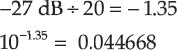
38 dB ÷ 20 = 1.9
101.9 = 79.4
79.4 × 0.013 V = 1.0326 V
The microphone can put out a little over 1 V, but the camera’s input overloads at 48 mV (0.048 V). We’ve got a significant problem, at least potentially. First let’s see what the maximum SPL is that we can record without mic preamp distortion. To do this, compare the sensitivity of the mic to the input overload:
![]()
So the output of the mic can be 3.692 times the level it would put out at the standard reference SPL of 94 dB. What is that in decibels?
![]()
And 94 dB SPL, which is the level for 13 mV, plus 11.3 dB, which is the factor above 94 dB where the mic input distorts, is 105 dB SPL.
Many scenes fall under 105 dB SPL, and much of the time you’ll get away with a setup that plugs this mic directly into this camera. For instance, the ordinary dialogue measured in the table is easily accommodated, with about 19 dB remaining as headroom, plenty to accommodate even short-term peaks. Conveniently, the Panasonic camera supplies phantom power to the microphone, so all you need is the mic and an XLR cable and you’re in business. You’ll also need accessories such as a boom pole, shock mount, and windscreen, but these are incidental to our purpose here. However, if the actor suddenly shouts, the signal output by the mic will increase greatly in level and it is almost certain that gross distortion will result, even if the main level control is jerked down; to reiterate, the distortion is occurring when the signal output by the microphone overloads the camera input before the opportunity arises to reduce the signal with the main level control.
With this simple connection, then, you must beware of sounds above 105 dB SPL—they will distort. Because the mic can handle 132 dB cleanly, and the camera input only 105 dB when the two are directly connected, what we need is a pad, a kind of neutral density filter for sound. A neutral density filter is a gray glass disc put in the light path of the lens that is used to reduce the intensity of bright scenes to the capability of the camera’s light sensor. Likewise, a pad is a device to knock down the level of the output of the microphone so that louder scenes can be recorded without distortion.
What we need is simple: a 27 dB pad, if we want to maximize the capability of the system, matching the maximum undistorted output of the microphone to the maximum undistorted input of the camera. Unfortunately, however, it’s not a simple thing to just go to the store and buy such a device. Perhaps you could get a 20 dB pad premade, but not a 27 or even 30 dB one (most audio people have never heard of such large amounts of padding!). So we’ll have to build one (Fig. 6-2).

Figure 6-2 The exterior of a custom-built pad.
The first thing to understand is that by putting a pad between the output of the microphone and the input of the camera, we are giving up on the phantom power capability of the camera supplying the microphone, and we’ll have to supply power externally. A battery-powered box in line will do the job; one such is the Professional Sound Corporation (PSC) 48PH phantom power supply. Follow that with a 27 dB pad on the way to the camera and we will have achieved our purpose.
A pad for a balanced line such as a microphone line consists of three resistors (Fig. 6-3). 9 Pin 1 of an XLR connector is both ground and the shield connection and is wired through (pin 1 female to pin 1 male) and connected to the body of the connector as well. Pin 2 is connected with a series resistor between input and output, as is pin 3. A parallel resistor goes across pins 2 and 3 of the male end of the connector. Together, the three resistors form a voltage divider. Here is how it is calculated:

Figure 6-3 The schematic of a pad, showing the XLR pin numbers.
We need a –27 dB pad. We select a 1 kΩ resistor for the branch that is in parallel with the camera input, 10 and now we have to calculate the two series resistors (Fig. 6-4). First think of them as one. The parallel branch represents the fraction of the voltage that we want delivered by this voltage divider. The equation for such a voltage divider is:
![]()
Since –27 dB is another decibels ratio, we can undo it as before (divide by 20, the result raised to the power 10x):
Thus, for our desired resistance,
![]()
Doing some high-school algebra means rearranging terms to solve for x:
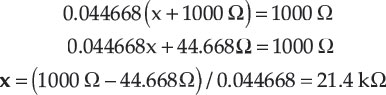

Figure 6-4(a) In our example, a 1 kΩ resistor is first mounted between XLR pins 2 and 3 of the male connector side of the barrel adapter.

Figure 6-4(b) Then, two 10.7 kΩ series resistors are added as shown. The free ends are then clipped and extended with hookup wire to the corresponding pins 2 and 3 of the female connector, as is the ground, pin 1.
Dividing this in two to build our balanced pad makes it 10.7 kΩ. Looking up the closest 1 percent resistor from an E96 chart of values, we find 10.7 kΩ falls exactly on a 1 percent part value. (For the case of any arbitrary pad value, the closest 1 percent values have a negligible error for this purpose.)
So, with this pad in our system, we can now record up to 132 dB SPL cleanly. Because this is a higher level than most people have heard of (after all, isn’t 120 dB the threshold of pain?), aren’t we being a little crazy? Well no, not really. An actor screaming measured 0.5 m away produces peaks of 128 dB SPL, and Lewis Fielder has recorded maximum peaks of 129 dB in the audience at 36 live music concerts. 11 This is close enough to 132 dB that having a method of recording to higher levels without distortion, for unusual situations, would be a good idea. For instance, I (Holman) measured the peak level inside the bass drum head of REO Speedwagon in the early 1970s and got 138 dB!
There is a way to record with low distortion to higher levels than 132 dB with this and similar microphones: add an additional pre-electronics pad. A pre-electronics pad is inserted between the microphone pickup capsule and the microphone’s own electronics. It reduces the level before distortion can occur within the microphone electronics, and raises the headroom correspondingly. For some models of microphones, these are built-in and switchable. For the Schoeps mic, they come as screw-in devices made in two values: 10 and 20 dB, Schoeps models DZC 10 and DZC 20, respectively. For instance, I had to use the DZC 10 attenuators to record the University of Southern California marching band at homecoming because of the high peak levels that a marching band can produce. With these in place, we can record levels up to 142 or about 150 dB SPL for the two models, respectively. Note that levels above 140 dB cause instantaneous hearing damage and so should be approached with caution. For the loudest screams of an actor, the 27 dB pad described previously is perhaps just enough, but without much headroom for instantaneous peaks, and perhaps a 10 dB pad would be warranted if the boom mic is near the actor, as well as earplugs for the boom operator! Also, with these pads you could record some kinds of gunfire cleanly at reasonable range, but you’d better be wearing hearing protection. In some extreme instances of close gunfire, it is possible to stretch the microphone diaphragm beyond its elastic limits and wreck it.
One reason that sound levels in the 135 to 140 dB range sound unusual to many knowledgeable people is that in many publications, tables of sound pressure levels for many everyday activities are given as average levels over a period of time. Louder sounds than speaking, when evaluated in the short term instead of as a long-term average, can produce correspondingly higher levels. For instance, a bus passing by when viewed from a seat at the bus stop in an urban setting measured 107 dB peak. The combination of the Schoeps microphone and the Panasonic camera would distort on this combination without a pad for this rather ordinary scene.
At the other end of the dynamic range is the very quiet. Some very quiet things to record include quiet room ambiences, Foley sound effects such as clothing rustle, and the ticking of a clock as used in Bergman’s Cries and Whispers to indicate that the scene is quiet. This is not a sound design point to be overlooked on set: the sound of silence is not silence. Think of it this way: the picture equivalent of silence is going to black, not a view of an empty room. A quiet space might be represented by the sound of a fly, a single cricket, or some such, but it would rarely be represented as pure silence.
Recording such quiet sounds requires quiet microphones and quiet electronics. The Panasonic camera has 69 dB dynamic range below its input overload of 48 mV. If we plug the Schoeps mic into the microphone input directly (no pads) because we’re recording quiet things, how quiet can they be? The simple way to calculate this is that it is 69 dB below the 105 dB SPL that we calculated previously. Why? Because that is the input overload point for no pad and the dynamic range with the microphone directly connected. The difference is the equivalent sound pressure level of the camera preamplifier noise, 36 dB SPL, subjectively about 16 times noisier than our hearing threshold. And it is 20 dB noisier than the microphone, from its specifications, so the camera preamp noise masks or conceals the real noise floor of the microphone. The combination may do well enough in shooting ordinary scenes, but in order to reach down to the quietest acoustic levels, a quieter external preamplifier is going to be needed.
The Sound Devices 442 is a battery-powered field mixer with 115 dB dynamic range 12 on its microphone inputs—a number derived from its specifications. Comparing its dynamic range to that of the camera shows an improvement of 115 dB minus 69 dB, which equals 46 dB. With each 10 dB representing subjectively twice the dynamic range, these dedicated mic mixers are at least 24 times quieter than the camera’s electronics. Furthermore, doing some more calculations shows that the 442’s equivalent input noise is about 12.5 dB quieter than the microphone, thus making it’s noise floor negligible in this comparison.
To use a dedicated microphone mixer, its output, set to line level, should be sent to the camera’s inputs, also set to line level. Be absolutely certain that both the output of the mixer and the input of the camera are switched to line level, because feeding a line-level signal into a microphone-level input, even if line up on tone can be done correctly, will cause serious distortion. Set up properly, the combination of the Schoeps mic and the mixer will be able to record sounds with far less noise than could be achieved by plugging the mic directly into the camera’s microphone input.
If we are really going for the quietest sounds, we might want to pick a microphone with an even lower noise level like the Neumann TLM-103. By virtue of its large diaphragm, it can be quieter than the Schoeps, at the expense of having greater variation in the off-axis frequency response. Thus we probably would not want to use the Neumann as a boom mic because, among other things, it is much larger and heavier, but it may excel as a specialized Foley mic, for instance. Its noise floor is equivalent to 7 dB SPL (A weighted), about the lowest among recording microphones, and its sensitivity is such that the output noise is still above the noise floor of typical field mixers.
To come full circle, what about the other end of the dynamic range, the loud end, for these combinations: the Schoeps and the Neumann microphones into the mixer? The Schoeps can produce about 1 V, but a Shure FP-33 mixer, for instance, distorts at an input level 10 dB less, thus requiring a 10 dB pad in order to reach 132 dB SPL. Unfortunately, putting in such a pad will kill the phantom power available from this mixer, and we’ll have to use an external power supply, just as described for the Panasonic camera. With the simple connection without an external power supply and pad, and the Shure providing the phantom power, the combination clips at 122 dB SPL, useful for many day-to-day purposes, but not reaching the highest levels of a screaming actor without distortion.
The Neumann has a maximum output level of 3.5 V, so with the Shure mixer a 21 dB pad will take the undistorted equivalent level up to 138 dB SPL, or, looked at another way, with no pad a level of 117 dB SPL can be handled by this combination.
While we’ve discussed handling loud sounds and soft ones, what if they happen simultaneously within one scene? This might occur if an actor in a quiet space, murmuring to himself, suddenly shouts.
Digital overload, like microphone preamplifier clipping, comes on abruptly and generally sounds pretty horrible. It is most noticeable on voice content in the vowels. Consonants are sharper, harder, faster sounds, which means they take up a wider frequency range, thus tending to hide distortion. Vowels, on the other hand, have a more orderly waveform, repetitive from cycle to cycle, and a well-defined fundamental and harmonics at twice, three times, and so forth times the fundamental frequency. This spectrum means that distortion, which tends to spread the content across a wider frequency range, will not be masked or hidden. So the first thing to give an indication of distortion is typically distorted vowels.
The most common way to handle a scene with wide dynamic range is to ride the gain, that is, adjust the microphone channel level control to adapt to the sound being recorded so that the loud passages don’t distort and the soft ones are well above the noise level of the electronics. Naturally, this is only effective if the potential distortion is caused by over-recording on the medium and not clipping at the microphone input, as described earlier. Riding, or adjusting the gain constantly, does no good if the signal is already distorted or noisy because of the conditions at the microphone preamplifier input. The main recording level control on cameras or mixers is after the microphone preamplifier, so its use is to adapt the dynamic range presented at the output of the microphone preamplifier to the dynamic range of the medium.
There are two contravening factors at work here. Constantly adjusting the gain means that within a given take the recorded level goes up and down so that the foreground sound, usually speech, is well recorded. A problem with this method is that then the background sound is constantly varying. This causes problems editorially, where a cut between two recorded sections could result in a large change in the background sound. So there are two conflicting goals for the production sound recordist in this situation:
Keep the foreground sound undistorted in loud passages by turning the level down, and not electronically noisy in quiet passages by turning the level up to keep the signal above the noise level of the medium.
Maintain the one best level within a whole scene, including shot-to-shot setup variations, which will produce the most cuttable sound by not riding the gain.
How does this dilemma get resolved? First, the degree of the dilemma depends on the dynamic range of the recorder. When early film sound optical tracks had little range, about all that could be done was that in order to have something sound loud, something quiet had to come before it—it was only through contrast with the quiet preceding passage that something could be made to sound loud. This was called “the cinema mixer’s trick.” There really wasn’t any dynamic range to spare.
With modern high-capacity recording, less gain riding needs to be done, because the range is larger. However, that doesn’t mean that you cannot protect the loudest sounds from distortion—you should. What it does mean is that through training and experience one comes to know what is acceptable in terms of gain riding. It is especially helpful if you edit your own sound recordings, because the feedback that this produces makes you a better mixer. No one prescription can be given, except to consider the following:
Human mixers, as opposed to limiters and automatic gain or volume controls called compressors, can anticipate the action, particularly if there are rehearsals for a fiction piece. One can sneak the gain riding in before it is needed and in an otherwise quiet place.
Boom operators can be especially helpful in leveling out performances from various actors/subjects. This is particularly true if a hypercardioid rather than a shotgun microphone is in use because the hypercardioid typically has much smoother response off-axis: it sounds mostly just like attenuated on-axis sound, so a stronger actor can be picked up at a more off-axis angle, while a weaker one is favored by being recorded on-axis. If this is tried with a shotgun, the off-axis sound coloration is too great to accept.
Certain sounds can afford to be recorded with distortion, because they are distorted anyway. Gunshots come to mind: keeping them within the undistorted range in a scene containing other sounds to be recorded would probably require just too much change of the background sound to accommodate good recording. It is easier to simply let the system distort briefly, and then, if needed, edit in cleaner gunshots in postproduction.
Once a wide dynamic range is available—say by use of an external mixer and staggered levels between the two channels as in the following discussion—then riding the gain gives way to setting the level, that is, setting the level just once for the loudest part of the scene to be certain it’s undistorted, then leaving it alone. This produces the most editable sound. Any gain riding that will be necessary for intelligibility and performance can then be done in postproduction, when there is time to go over and over it as many times as necessary.
Another specialized way to get a gallon of dynamic range into the half-gallon of the camera’s dynamic range is to divide the gallon into two different half-gallons. You could, for example, following the microphone battery power supply, put in a Y-adapter and send one signal to both inputs of the camera, with one of them having a pad and the other having no pad. In this way, the padded version would capture the loudest part of the performance cleanly, but with noisy lower-level passages, while the second channel would have distorted high-level passages but be quieter in low-level ones. This requires a lot of coordination between production and postproduction sound—after all, one track will be distorted some of the time, but it is a way of capturing a wider range and using the second channel, when what is desired is monaural (single microphone) boom operation.
Using this tactic with the Schoeps mic and Panasonic camera, for instance, could theoretically extend the dynamic range of the recording from 69 dB to 69 plus 27 dB which equals a 96 dB range, a great improvement. That would cover sounds from an equivalent 36 dB to 132 dB SPL. We’ll see how to set the levels on this combination in the next section.
Multiple Level Controls in the Chain
A chain consisting of a microphone and two potential places to pad its output has been described. Real-world situations with a camcorder using an external mixer have many more points in the system where the level may be affected. For instance, in the order that the signal encounters them, these could be:
Microphone pre-electronics pad, previously described.
Microphone level in-line pad, previously described, which may be a part of an external power supply or a separate device placed in the microphone line. If one is used, it does not pass phantom or T power, which must be supplied before the pad (often in the same box as the pad).
Mixer’s input sensitivity switch, Mic/Line, or various Mic levels and Line. For instance, changing from 48 V phantom power (implying an electrostatic microphone) to a DYN input (for an electrodynamic microphone) may adjust the input sensitivity of the mixer, because electrostatic mics are normally “hotter” than electrodynamic mics (more output for the same SPL) by something on the order of 20 dB.
Mixer’s input trim control (pad). Replaces the need for external microphone-level pads with a variable input gain or pad on the mixer. This is only available on typically larger and more expensive mixers.
Mixer’s channel level control.
Mixer’s master level control.
Mixer’s output level switch: Mic/Line. This switch is provided so that if the only input provided by the camera is at mic level, it will not be overloaded. If mic/line switching is available at both the mixer output and the camera input, line level is preferred because the higher level is less susceptible to electrical interference.
Camera’s input level switch: Mic/Line. Set to correspond to mixer’s output.
Camera’s input level control.
Camera’s monitor level control. Also, there is often a switch that provides monitoring for channel 1, channel 2, or channel 1 plus channel 2.
Mixer’s monitor return level control.
Mixer’s headphone level control.
Standalone headphone level control, such as in a distribution box for production sound operator and boom operator (potentially separate).
At first this can seem to be almost hopelessly complicated, because there are so many places for the level to be set. One of the primary reasons for this is that each component part in the chain has to be prepared in the marketplace to face all kinds of conditions; hence, for instance, the mic-level output on a microphone mixer. That only exists because sometimes the only thing available on the next piece of gear is a microphone input, but there is a way to simplify the settings for this chain. First is to understand the signal flow through the chain so that troubleshooting can be done if the signal goes awry. Second is to know the nominal setting of all parts of the chain, so you know when you are deviating from normal. Third is to calibrate the level for those parts of the chain that are metered, so that the mixer and camera are adjusted to the same sensitivities, and what is read on the mixer will read on the camera; then the mixer becomes an extension of the camera. Fourth is to understand the consequences of getting the levels wrong. Let’s take each of these up in turn:
The signal flow is given in the aforementioned order. However, it is a fairly comprehensive list, and any single set of equipment may have fewer parts. It is worthwhile to draw a diagram of your particular system with all of the places that affect level, so that you can follow the logic. A typical example with an external mixer and using single-system recording is given in Figure 6-5.

Figure 6-5 Block diagram of single-system shooting setup with external microphone mixer. The return of the headphone signal from the camera to the mixer, and monitoring by way of that path, ensures that the signal has made it to the camera.
We’ve already had a discussion about the dynamic range at the mic and on the medium. Setting levels correctly helps the gallon into half-gallon into quart problem, and some of this has already been discussed in the context of the microphone input. For the whole system, nominal settings need to be applied. For instance, it is useful to know that level controls normally are run at 7 on a scale of 10 or near 0 dB (unity gain) on a scale from –∞ to +15, that headphone monitor controls on camera are often operated fully up, and so forth.
Calibration is necessary in a system with a separate mixer and recorder. Start with a tone generator from the mixer, set to a standard level such as 0 VU, and then set the mixer output switch to line level, the camera input sensitivity switch to line level, and adjust the camera input level control for a standard meter reading, such as –20 dBFS. Because two different types of meter are in use, VU and digital peak, the readings for the nominal setting are not the same.
The consequence of getting the level wrong at one point in the chain and making up for it at a later point can be added distortion or noise. This may be a small problem or an overwhelming one, depending on the degree of the mismatch. Say in one stage the level is down by 10 dB and then subsequently restored to full level. Any noise added to the signal in stages between the two level controls will be exaggerated by 10 dB. Worse is clipping distortion early in the chain, which we attempt (unsuccessfully) to fix later in the chain. Once clipped, the signal remains distorted no matter what you do with subsequent level controls.
Another Kind of Overload Distortion and How to Avoid It
So far we have described the overload distortion called clipping and explained how to use pads before and/or after the microphone’s own electronics to maximize headroom. There is an invisible type of this overload possible too, and it plagues all directional microphones especially: infrasonic overload. Directional microphones of all types are much more susceptible to wind noise, boom panning noises, and other very low-frequency noises, compared to omnidirectional types. But directional mics are necessary in most film/video recording applications, just to emphasize the direct sound and suppress reverberation and noise occurring in most settings. The only exception to this rule is for lavalieres, which are mostly omnidirectional and therefore less wind susceptible than other types.
Infrasonic (formerly called subsonic) overload from wind or boom panning leads to bobbles in the audio—little moments of time where the sound seems to be compressed or even go away. Once you’ve heard it, you’ll be able to recognize it. Electronic infrasonic overload may occur at two potential places in the chain: right in the microphone’s internal preamplifier or in the camera or mixer’s microphone preamplifier. Either of these may be prevented by putting a pre-electronics low-frequency filter (called alternately low-cut or high-pass) between the pickup capsule and the microphone body. In the case of the Schoeps, this is a screw-in device called a CUT-1, with adjustable low-frequency response above a steep cutoff frequency. In some other microphone models, the low-cut switch may be built in; however, in that case it is not necessarily clear whether the low-cut switch occurs before or after the electronics. Placing it before the microphone’s own electronics most improves the headroom, whereas placing it after protects the rest of the chain—in particular, the microphone preamplifier in the camera or mixer—from infrasonic overload.
Generally speaking, for recording dialogue one can use a 60- or 80-Hz high-pass (low-cut) filter and do little or no damage to the voice while decreasing the intensity of wind and panning noises dramatically. This is especially true of steep filters, like the Schoeps CUT-1, a 24-dB/octave filter below 60 Hz. 13
Combining Features for Best Wind Performance
The combination of ingredients that produces the lowest wind susceptibility involves using an omni pickup capsule, protecting the capsule from wind, protecting the electronics from low-frequency and broad-frequency range overload, and protecting the camera or mixer microphone input from excessive amounts of signal (Fig. 6-6). A system consisting of a Schoeps MK2 omni capsule plus DZC20 pad plus CUT-1 filter plus CMC electronics plus BBG windscreen with Windjammer should have the greatest attenuation of wind effects possible. The output level of the mic should be scaled to the input capability of the mixer, possibly with an additional pad, and an additional mixer high-pass filter might not be out of place (Tables 6-2 and 6-3). An omni capsule implies that one must use the closest possible working distance, but the advantage of low wind susceptibility may overcome the working distance problem.

Figure 6-6 Various combinations of microphones, pads, power supplies, mixers, and cameras for the various sound pressure level and wind noise conditions encountered. Required shock mounts and booms are not shown. (Other useful combinations of microphones and windscreens can be found at www.schoeps.de/E-2004/windscreens-select.html.)
Table 6-2 Some common microphone specifications.

*A weighted
Values in parentheses are with built-in pad enabled.
Table 6-3 Input overload and pad values needed for selected microphones with selected audio inputs to match the microphone maximum output to the electronics microphone input maximum undistorted level.

Microphone electrical outputs have a potentially very wide dynamic range, from very small to rather large voltages depending on the scene they face. The range can be tamed through the use of pads, which work like neutral density filters.
If the microphone output voltage exceeds the input capability of the microphone preamp, the sound will be distorted no matter where the level control is set. Pads are necessary to keep the maximum output of the mic from exceeding the input capability of the preamp.
Setting the record level is the most important act of a recordist. Because digital recording distorts abruptly when overloaded, it is better to under-record somewhat than risk ever over-recording.
To record very soft sounds, like Foley and some ambiences, a camera mic preamplifier may be too noisy, and use of a better outboard mixer or preamp is necessary to avoid hearing hiss.
Multiple level controls in the chain can be confusing, and the best way to work through the confusion is to know what the nominal settings of all the controls and switches affecting level in the chain are and to set them there to start.
Wind noise can be avoided through use of omnidirectional microphones, high-pass filters, and efficient windscreens.
1 Sound Pressure Level, dB relative to the threshold of hearing, which is a pressure of 20 μN/m2.
2 In order for the second channel recording to remain clean, the levels must be offset at the proper place in the recording chain as described later in this chapter. In the case of a microphone plugged directly into the camera, the recorded level can be offset using the camera’s audio gain controls, but if the microphone is plugged into a mixer or recorder as described below, it is better to offset the level at the first possible point in the chain: once a signal distorts, it cannot be saved by turning the level back down at a later point in the audio processing chain.
3 For aficionados, the reason this is not 96 dB is because of the necessity for dither to linearize the medium. Dither is some deliberately added low-level noise used to smooth the steps of the medium.
4 For experts, this was from the 1-kHz clip point to the weighted noise floor, weighting consisting of a 400-Hz high-pass and a 22-kHz low-pass filter. This seemed appropriate because the camera had a lot of low-frequency noise, which is usually acceptable because it is less audible than mid- to high-frequency noise.
5 dB is used colloquially here and at many places in the text. Strictly speaking, the term dB only specifies a ratio, and without further delineation is unclear. The term SPL is implied anytime we are speaking of acoustical levels.
6 These numbers were measurements of the author Holman talking at 0.5 m, measured LAeq (for the 65 dB SPL measurement) and impulse peak (35 ms) on a B&K 2230 sound level meter.
7 Boom operator Don Coufal, production sound mixer Jeff Wexler, dialogue editor Laura Harris, re-recording mixers Rick Kline, Paul Massey, and Doug Hemphill. Dreamworks DVD 87818 Chapter 23, 3:30–5:52. Russell: “So, this is where the enemy sleeps.”
8 Weighting the noise floor means adapting the noise measurement with a frequency-by-frequency response curve, like a tone control, that more or less accounts for the low-level characteristics of human hearing.
9 Today at least. Very much older designs of pads had to take into account the source and load impedances in a matching type of impedance environment, such as 600 ohms. Nowadays we don’t worry about such things because source impedances are so low and input impedances so high, although if we were to calculate the pad with the source and load impedances in place, we’d get a very slight difference in attenuation.
10 Because that will provide a low enough source impedance to drive a reasonable amount of cable.
11 Fielder, L.D., “Pre- and Post-emphasis Techniques as Applied to Audio Recording Systems,” J. Audio Eng. Soc., Vol. 33, pp. 649–658 (Sept. 1985).
12 This 115 dB of dynamic range may not be the actual performance because it may be measured at the two extremes: noise with the gain all the way up and referred back to the input, and headroom with the gain controls minimized for maximum headroom, two settings that can’t be achieved simultaneously.
13 If this particular Schoeps CUT-1 is used, there are other considerations: its use increases sensitivity by 5 dB, but decreases headroom by 5 dB. If an attenuator is also used, it is placed on the pickup capsule first, followed by the CUT-1 filter.