


Implementation of Storwize HyperSwap
In this chapter, we detail the Storwize HyperSwap steps.
3.1 Storwize HyperSwap implementation
For this setup, we used two Storwize V7000 that were already installed so the initial setup was not done, and is beyond the intended scope of this paper. To be able to cluster all the nodes in a single cluster together, at least one cluster has to be deleted. After the delete, the nodes are brought into a candidate state, which enables them to join an existing cluster. By doing this, the nodes are visible as candidates to the existing cluster and they are added to the cluster, which ends in a four node or two I/O group setup, as shown in Figure 3-1.
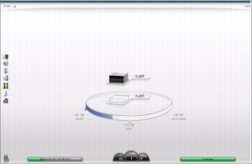
Figure 3-1 Adding nodes to a cluster
At this time, it is a normal Storwize V7000 cluster and there is no HyperSwap Cluster. To change it to a HyperSwap Cluster, make sure that you have fulfilled all the requirements, such as a dedicated SAN for internal communication and a quorum in a third site (FC storage or
IP Quorum).
IP Quorum).
If all prerequisites are fulfilled the topology can be changed to HyperSwap, this can be done via the GUI as described here, or via the chsystem command. Make sure that by doing this via the CLI that the Site IDs are set in advance.
To change the topology via the GUI, complete the following steps:
1. Go to the Action menu in the start screen and select Modify System Topology, as shown in Figure 3-2.

Figure 3-2 Modify System Topology
2. A wizard opens that guides you through the steps, as shown in Figure 3-3.

Figure 3-3 Modify topology wizard
3. The first screen of the wizard asks you to enter the site names. The default ones are used, but they can be changed to more descriptive names, such as Berlin or Backup-DC. You can leave them as they are here and change them later if required. This can be seen in Figure 3-4.

Figure 3-4 Assign site names
4. In the next wizard screen, the enclosures have to be assigned to a site. This is mandatory and has to be done correctly, because the code has to rely on this when the preferred nodes and paths are negotiated, so be careful and double check your actions. The location can be changed by clicking on the small blue button with the arrows. This is shown in Figure 3-5.

Figure 3-5 Assign enclosures
5. After the nodes get a site assigned, the host needs a site ID. Even if it is not mandatory as it is for the nodes, it is highly recommended to give a site ID (which reflects the location of the host) to every host. This enables the system to select the correct preferred path with the best latencies. This can be done for each host separately. See Figure 3-6.

Figure 3-6 Assign hosts to a site
6. After the hosts are assigned, now the external storage system has to be assigned to a site. At a minimum one system has to get a site, the quorum site (an exception is the usage of an IP Quorum). This is the third site (site 3) and is set by default as the active quorum. If there are other storage systems attached and virtualized, they should also get a valid site ID that reflects their location, because this gives greater efficiency. Assigning the quorum site is shown in Figure 3-7 and Figure 3-8 on page 16.

Figure 3-7 Assigning storage to Quorum site - 1
I
Figure 3-8 Assigning storage to Quorum site - 3
7. In the next screen you have to set the bandwidth which is available between both sites and can be used by the system. This is to limit the system and to not allow it to fill up a shared bandwidth. The bandwidth has to be sized carefully and checked from time to time if there are major changes. Also, the percentage of the bandwidth which can be used for background copies can be set. At the end you see the resulting Total background Copy calculated.
Setting the bandwidth is shown in Figure 3-9 (the numbers in Figure 3-9 are example numbers).

Figure 3-9 Setting the bandwidth between sites
8. Before the wizard is finished you will see a short summary of your setting and everything should be checked. If everything is as expected, click Finish to change the topology to HyperSwap. This is shown in Figure 3-10.

Figure 3-10 Summary
9. In the System view, you see the result (this is also the entry screen), with the sites and the hardware located in the sites. This is a sign that HyperSwap is already active, as is shown in Figure 3-11.

Figure 3-11 Active HyperSwap
10. In Create Volumes, the HyperSwap volume is offered, and here you can create a new HyperSwap where all the settings (creation of IBM FlashCopy® mappings, creation of relationship, and so on) are done using the GUI.
As with any other creation you can select the size, number of volumes, and the pool where the volumes should reside. The site ID is realized by the GUI, so pools from both sites are involved. Creating a HyperSwap volume is shown in Figure 3-12.

Figure 3-12 Creating a HyperSwap volume
11. The results are the HyperSwap volumes with all the volumes for Metro Mirror, FlashCopy, and so on, as can be seen in Figure 3-13.

Figure 3-13 HyperSwap volumes
3.2 Configuration of IBM i
On each site, we use a POWER server with an IBM i logical partition connected with two Virtual I/O servers (VIOS) in N-Port ID Virtualization (NPIV) mode.
Two SAN fabrics are implemented, one switch in each fabric on each site. The switches of the same fabric are connected by an Inter Switch Link (ISL). Each switch is divided into one part for the private fabric and one part for the public fabric.
Each VIOS is connected to the SAN with two FC ports, one port to each public fabric.
We use a Storwize V7000 at each site. Each node of the Storwize is connected to the SAN with four ports: a port to Private Fabric A, a port to Public Fabric A, a port to Private Fabric B, a port to Public Fabric B.
The quorum disk resides on the DS8000 which is connected to Public fabric B at either site.
The connection scheme is shown in Figure 3-14.

Figure 3-14 Connection scheme
..................Content has been hidden....................
You can't read the all page of ebook, please click here login for view all page.