Introduction
Abstract
This chapter introduces the current problems of infrastructural systems. It starts by briefly reviewing the causes of deterioration of conventional concrete and steel, and then go on to reveal the financial consequences of deteriorating infrastructures. Following this discussion, an analysis of fiber-reinforced polymer (FRP) and its available systems for strengthening will be presented. Finally, a full discussion of various strengthening schemes, design guidelines, and installation precautions for FRP is included at the conclusion of the chapter.
Keywords
Fiber-reinforced polymer (FRP); infrastructural problems; strengthening of structures; FRP installation; design guides
1.1 Overview
Various causes contribute to the deterioration of the civil infrastructure. Although bridges are generally expected to have a service life of 50–100 years, many are showing signs of distress much earlier. Extreme temperatures in the summer and winter, including many cycles of freeze thaw, and the use of deicing salts, are significant factors that contribute to the progressive damage of bridge structural members (Staton and Knauff, 2007). Other factors include heavy traffic loading, lack of adequate maintenance, and collision damage.
In the United States, State Departments of Transportation (DOT) conduct regular inspections of transportation structures such as bridges. Bridge inspection and reporting by DOTs are part of the larger, federally mandated National Bridge Inspection Standards (NBIS) administered by the Department of Transportation (USDOT) Federal Highway Administration (FHWA) (USDOT-FHWA, 2004). According to FHWA data, in 2009, 5% of bridges on the National Highway System were structurally deficient, 17% were functionally obsolete, and about 35% had superstructures rated less than in “good” condition. Unsurprisingly, older bridges are more likely to have problems. Considering all bridges, for example, the proportion of structurally deficient and functionally obsolete bridges exceeds 40% for structures 51–75 years old, and from 54 to 65% of the structures older than 75 years are deficient or obsolete (FHWA, 2010).
Depending on the nature and severity of the deficiency, different corrective actions may be required. Traditional methods of strengthening and rehabilitating steel bridges include the replacement of damaged structural members, repair of corroded beam ends, addition of stiffeners, and application of protective coatings (Wipf et al., 2003). For concrete bridges, traditional rehabilitation measures may include sealing hairline cracks using epoxy injection, spot-patching damaged areas, waterproofing, jacketing structural members to restore or increase their load carrying capacity, and cathodic protection against reinforcement corrosion. However, traditional methods have inherent limitations. For example, spot-patching methods can mend corrosion-induced spalls, but typically do not retard chloride-induced corrosion; corrosion rates have been observed to be higher at the perimeter of a patch and are independent of the type of patch material used (Tabatabai et al., 2005). Moreover, these traditional repairs are often expensive and disruptive to traffic, particularly for bridges. As such, an alternative that is growing in popularity is to utilize fiber-reinforced polymer (FRP) composite materials.
FRP has been used for strengthening applications in various industries. However, common applications for bridge components involve externally bonded (EB) composite fabrics or jackets on beams, columns, and bridge decks, where significant improvements in compressive, shear, and flexural performance has been obtained (Nanni et al., 1992; Karbhari et al., 1993; Saadatmanesh et al., 1994; Chajes et al., 1995; Labossiere et al., 1995; Seible et al., 1997; Nanni, 2000; Mo et al., 2004; Nanni, 2004; Ludovico et al., 2005; Walker and Karbhari, 2006; Mertz and Gillespie, 1996; Miller et al., 2001; Tavakkolizadeh and Saadatmanesh, 2003; Rizkalla et al., 2008; Elarbi, 2011).
Advantages of FRP include a high strength-to-weight ratio, light weight, excellent corrosion resistance, and ease of installation. Because of their light weight, FRP composites are cheaper to transport, require no formwork and less or no scaffolding to install, and minimally add to a structure’s dead load. Due to the strength of FRP composites, often only thin layers are needed to rehabilitate beams and columns, minimally altering original dimensions. In some cases, this may become important to maintain vehicular clearance and other tolerances within acceptable limits. Corrosion resistance is a principal advantage, as steel reinforcement corrosion has long been recognized as a significant and costly maintenance problem.
In general, for the external application of FRP sheets, a layer of dry fiber sheet (usually unidirectional tape) is placed on top of a coat of polymer resin that hardens to bond the fiber sheet to the concrete structure. However, wet lay-up, precured, and nearsurface mounted construction techniques have been used in practice. When needed, multiple layers of fiber sheets can be sequentially added by repeating the application procedure. The resulting properties and potential failure modes of the FRP composite member are a function of the properties of the original member, the FRP, and their interfaces. The interface between the FRP sheet and the structural member, usually concrete, is particularly important, since composite action requires a solid bond. Final failure is often caused by the debonding of the FRP sheet from the concrete substrate (Meier, 1995; Buyukozturk and Hearing, 1998). The degradation of a constituent in FRP over time affects various composite properties, and may even change the order of governing failure modes (Wu and Yan, 2013). This is a particularly important concern, as a FRP-bonded structure could fail abruptly due to a change in dominant failure mode.
1.2 FRP strengthening systems
Early fiber composite applications have mainly been limited to aerospace, chemical and shipbuilding due to cost and research limitations (Emmons, 1998). However, modern composites can be found in various forms from underground storage tanks to boat hulls and jet fighters. Carbon FRP (CFRP) strip bonding for structural repair and strengthening applications was first introduced in Switzerland by Meier in 1984 (Barton, 1997). Later, the California Department of Transportation, Caltrans, pioneered the use of FRP in the United States during the early 1990s by seismically upgrading bridge columns in California with Glass FRP (GFRP) fabrics (Sika Corp., 2012).
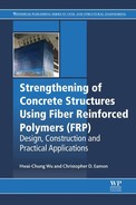
FRP is available in a variety of forms of interest to structural engineers such as bars, grids, sheets, and prestress tendons. Some of these components, such as those in bar and tendon form, are primarily used in place of steel reinforcement when new concrete members are cast. For existing concrete components, modern rehabilitation methods include the use of FRP composite sheets in the form of beam wrapping to strengthen flexural or shear capacity, column wrapping to enhance compressive and seismic performance, bonded FRP flange plates to increase bending capacity, and epoxying FRP rods in grooves cut into the substrate to increase member strength (Khan, 2010). One of the most flexible strengthening options is the use of EB FRP systems. Commercially available FRP systems are offered by suppliers such as Sika, Fyfe, and QuakeWrap. Systems are offered in either unidirectional or bidirectional fiber orientation. These systems are made of carbon fibers, glass fibers, or, for some bidirectional systems, carbon fibers in one direction and glass fibers in the other. Depending on the application, epoxy adhesives are an integral part of the system and can be formulated to provide a range of application characteristics and mechanical properties when cured. Epoxy formulation provides the bond between the reinforcing plies (laminate) and the concrete base, the bond between different plies, and a protective coat to shield the laminate from the elements during service life. Tables 1.1 and 1.2 present the physical and mechanical properties of a typical selection of unidirectional and bidirectional FRP strengthening systems offered by Sika and Fyfe.
Table 1.1
Properties of FRP systems from Sika and Fyfe
| Physical and mechanical properties of unidirectional FRP strengthening systems by Sika and Fyfe | ||||||||
| Sika unidirectional (0°) | Fyfe unidirectional (0°) | |||||||
| Unit | Sikawrap Hex 103C | Sikawrap Hex 117C | Sikawrap Hex 230C | Tyfo SCH-41 | Tyfo SCH-41-0.5X | Tyfo SCH-41-2X | Tyfo SCH-41H | |
| Fiber properties | ||||||||
| Tensile strength | psi | 550,000 | 55,000 | 500,000 | 550,000 | 550,000 | 550,000 | 675,000 |
| MPa | 3793 | 3793 | 3450 | 3790 | 3790 | 3790 | 4650 | |
| Tensile modulus | psi | 33,000,000 | 34,000,000 | 33,400,000 | 33,400,000 | 33,400,000 | 33,400,000 | 42,000,000 |
| GPa | 228,000 | 234,000 | 230,000 | 230,000 | 230,000 | 230,000 | 289,000 | |
| Ult. elongation | % | 1.50 | 1.50 | 1.50 | 1.70 | 1.70 | 1.70 | 1.70 |
| Density | lbs/in.3 | 0.065 | 0.065 | 0.065 | 0.063 | 0.063 | 0.063 | 0.065 |
| g/cc | 1.8 | 1.8 | 1.8 | 1.74 | 1.74 | 1.74 | 1.8 | |
| Laminate physical properties | ||||||||
| Fiber type | Carbon | Carbon | Carbon | Carbon | Carbon | Carbon | Carbon | |
| Color | Black | Black | Black | Black | Black | Black | Black | |
| Weight | OZ/Y2 | 18 | 9 | 6.7 | 19 | 9.5 | 40 | 24 |
| g/m2 | 618 | 309 | 230 | 644 | 322 | 1424 | 814 | |
| Ply thickness | in. | 0.04 | 0.02 | 0.015 | 0.04 | 0.024 | 0.08 | 0.04 |
| mm | 1.016 | 0.51 | 0.381 | 1.0 | 0.6 | 2.0 | 1.0 | |
| Cured laminate mechanical properties | ||||||||||||||
| Test | Design | Design | Test | Design | Test | Design | Test | Design | Test | Design | Test | Design | ||
| Tensile strength | psi | 123,000 | 104,000 | 105,000 | 129,800 | 104,000 | 143,000 | 121,000 | 137,000 | 116,000 | 143,000 | 121,000 | 200,000 | 170,000 |
| MPa | 849 | 717 | 724 | 894 | 715 | 986 | 834 | 944.6 | 799.8 | 986 | 834 | 1380 | 1.170 | |
| Tensile modulus | psi | 10,239,800 | 9,446,600 | 8,200,000 | 9,492,300 | 8,855,000 | 13,900,000 | 11,900,000 | 14,500,000 | 12,3000,000 | 13,900,000 | 11,9000,000 | 15,500,000 | 13,100,000 |
| MPa | 70,552 | 65,087 | 56,500 | 65,402 | 61,012 | 95,800 | 82,000 | 99,900 | 84,800 | 95,800 | 82,000 | 106,800 | 90,300 | |
| Tensile elongation | % | 1.12 | 0.98 | 1.0 | 1.33 | 1.09 | 1.00 | 0.85 | 0.95 | 0.80 | 1.00 | 0.85 | 1.30 | 1.10 |
| Tensile strength per inch width | lbs | 4928 | 4160 | 2100 | 1947 | 1560 | 5720 | 4840 | 3288 | 2784 | 11,440 | 9680 | 8000 | 6800 |
| kN | 21.9 | 18.5 | 9.3 | 8.7 | 6.9 | 25.4 | 21.5 | 14.6 | 12.4 | 50.9 | 43.1 | 35.6 | 30.2 | |
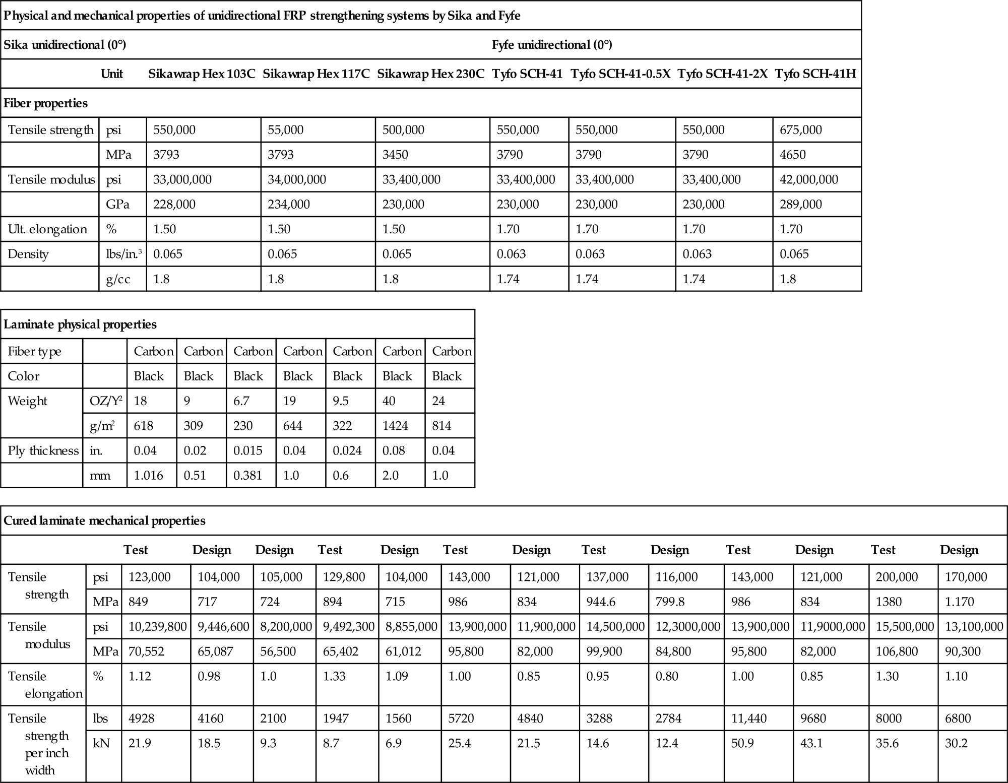
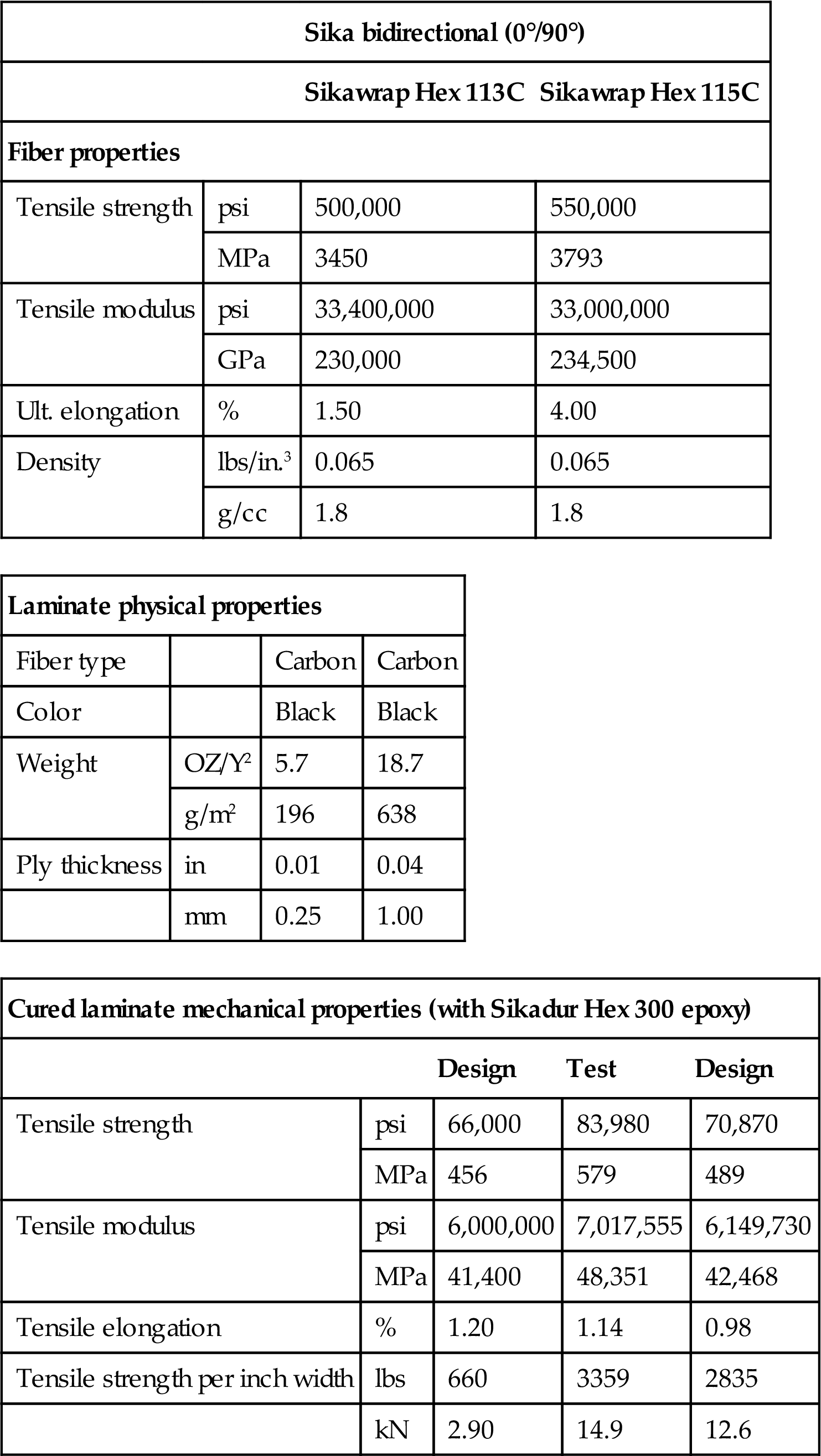
Table 1.2
Bidirectional laminate selection offered by Sika
| Sika bidirectional (0°/90°) | |||
| Sikawrap Hex 113C | Sikawrap Hex 115C | ||
| Fiber properties | |||
| Tensile strength | psi | 500,000 | 550,000 |
| MPa | 3450 | 3793 | |
| Tensile modulus | psi | 33,400,000 | 33,000,000 |
| GPa | 230,000 | 234,500 | |
| Ult. elongation | % | 1.50 | 4.00 |
| Density | lbs/in.3 | 0.065 | 0.065 |
| g/cc | 1.8 | 1.8 | |
| Laminate physical properties | |||
| Fiber type | Carbon | Carbon | |
| Color | Black | Black | |
| Weight | OZ/Y2 | 5.7 | 18.7 |
| g/m2 | 196 | 638 | |
| Ply thickness | in | 0.01 | 0.04 |
| mm | 0.25 | 1.00 | |
| Cured laminate mechanical properties (with Sikadur Hex 300 epoxy) | ||||
| Design | Test | Design | ||
| Tensile strength | psi | 66,000 | 83,980 | 70,870 |
| MPa | 456 | 579 | 489 | |
| Tensile modulus | psi | 6,000,000 | 7,017,555 | 6,149,730 |
| MPa | 41,400 | 48,351 | 42,468 | |
| Tensile elongation | % | 1.20 | 1.14 | 0.98 |
| Tensile strength per inch width | lbs | 660 | 3359 | 2835 |
| kN | 2.90 | 14.9 | 12.6 | |
1.3 Composite interfacial debonding
A critical concern of EB FRP reinforced structures is delamination, or debonding. Although detailed weather-induced bond deterioration is not fully understood, the results of debonding and its related failure phenomenon are well known. The quality of interfacial bonding has a strong influence on structural performance, as this significantly affects the composite action required for many applications, and ultimate failure of the strengthened component is often caused by debonding of the FRP sheet from the concrete substrate (Meier, 1995; Buyukozturk and Hearing, 1998).
1.4 FRP design standards and guides
Various documents have been developed in the last two decades describing FRP strengthening systems and provide guidelines for design assumptions and calculations. The most widely known guide in the United States is ACI 440.2R, Guide for the Design and Construction of Externally Bonded FRP Systems for Strengthening Concrete Structures (2008). A number of reports issued by the National Cooperative Highway Research Program (NCHRP) are design/construction guides for FRP systems and include:
• NCHRP Report 678, Design of FRP Systems for Strengthening Concrete Girders in Shear (Belarbi et al., 2011).
• NCHRP Report 655, Recommended Guide Specification for the Design of Externally Bonded FRP Systems for Repair Strengthening of Concrete Bridge Elements (Zureick et al., 2010).
• NCHRP Report 564, Field Inspection of In-Service Bridge Decks (Telang et al., 2006), which contains a manual for the in-service inspection of FRP bridge decks.
• NCHRP Report 514, Bonded Repair and Retrofit of Concrete Structures Using FRP Composites (Mirmiran et al., 2004), which describes recommended construction specifications and a control process for FRP strengthening including material preparation, application, a QA/QC plan, as well as training, qualification, inspection, and maintenance recommendations.
Other US and international guides include:
• AASHTO (2013), Guide Specifications for Design of Bonded FRP Systems for Repair and Strengthening of Concrete Bridge Elements.
• AC125 (2012), Acceptance Criteria for Concrete and Reinforced and Unreinforced Masonry Strengthening Using Externally Bonded Fiber-Reinforced Polymer (FRP) Composite Systems. AC125 is issued by ICC Evaluation Service to establish minimum requirements for the issuance of evaluation reports on FRP composite systems under the 2012, 2009, and 2006 International Building Code (IBC) and the 1997 Uniform Building Code (UBC).
• ACI 440.3R (2004), Guide Test Methods for Fiber-Reinforced Polymers (FRPs) for Reinforcing or Strengthening Concrete Structures.
• ACI 440R (2007), Report on Fiber-Reinforced Polymer (FRP) Reinforcement for Concrete Structures.
• ACI SP-215 (2003), Field Applications of FRP Reinforcement: Case Studies.
• ISIS (2008), Design Manual No. 4, FRP Rehabilitation of Reinforced Concrete Structures, issued by the Canadian Network of Centers of Excellence on Intelligent Sensing for Innovative Structures.
• CEB-FEB (2001), Bulletin No. 14, Externally Bonded FRP Reinforcement for RC Structures, contains design guidelines for the use of FRP reinforcement in accordance with the design format of the CEB-FIP Model Code and Eurocode2.
• CNR-DT 200 (2004), Guide for the Design and Construction of Externally Bonded FRP Systems.
• Japanese Society of Civil Engineers (1997), Recommendations for Design and Construction of Concrete Structures Using Continuous Fiber Reinforcing Materials.
• Japan Concrete Institute (1997), State of the Art Report on Retrofitting with CFRM, Guidelines for Design, Construction and Testing.
• TCS (2000), Design Guidance for Strengthening Concrete Structures Using Fiber Composite Materials, Technical Report 55, United Kingdom.
1.5 Designing with FRP reinforcement
In the civil infrastructure, FRP is typically used to strengthen reinforced concrete bridge elements. A reinforced concrete element strengthened with FRP is a member consisting of three materials: concrete, steel, and FRP, where the FRP supplements the existing steel reinforcement. The application of FRP requires engineers to address the interaction of these three materials, with each material having different material properties and statistical variation. This latter issue is critical to address for a design guide that falls within a modern, probabilistically calibrated load and resistance factor design format. To account for uncertainties in material properties, design formulations addressing each material’s contribution to the overall strength (Rn) of the element can be based on individual reduction factors applied separately to each of the materials constituting the composite (concrete, steel, and FRP); a combined reduction factor applied to the entire composite; or a combination of the two where both individual and combined reduction factors are applied to the system (Sika, 2012). For example, ACI 440.2R-08 recommends the use of ACI-318 (steel) reinforced concrete resistance (ϕ) factors applied to the overall element strength, in combination with an additional FRP reduction factor ψ, which takes into account the effects of FRP material property variation.
1.5.1 Flexural strengthening
To account for the complex behavior and various possible failure mechanisms of FRP-bonded structures, extensive experimental investigations were carried out by numerous researchers (Seible et al., 1997; Mo et al., 2004; Nanni, 2004; Ludovico et al., 2005; Walker and Karbhari, 2006, among many others). For FRP bonded flexural beams, several failure modes were generally observed:
1. Crushing of the concrete in the compression zone before rupture of the FRP sheet or yielding of the reinforcing steel (brittle failure).
2. Yielding of the tension steel before concrete crushing or rupture of FRP sheet (ductile failure).
3. Yielding of the compression steel reinforcement of a doubly reinforced section (relatively ductile failure).
4. Rupture of the FRP sheet before steel yield and the compressive strain in the concrete is below its ultimate strain (the most brittle failure).
5. Anchorage failure (delamination) in the bond zone of the FRP sheet (often a ductile failure).
6. Peeling or shear/tension failure of the concrete substrate near the FRP sheet’s cut off zone (brittle failure).
These six failure modes were classified into two types by Thomsen (2004). Type one includes modes exhibiting composite action up to failure, either due to concrete crushing, FRP rupture, or lack of shear resistance. Type two consists of failures by loss of composite action due to debonding of the FRP sheet, or by end peeling, where the concrete cover near the support regions peels off. To avoid detachment failure at the FRP/concrete interface, existing guidelines often attempt to curtail the allowable interface strain. For example, ACI 440.2R (2008) introduces a bond reduction factor (km) to limit the strain permitted in the FRP system. According to ACI 440.2R, km is taken as a value not greater than 0.9, which reduces the usable strength of the FRP below its ultimate rupture strain. Even so, FRP rupture or delamination might occur if the FRP or bond strength later deteriorates. However, provided that the bond remains sufficiently strong to avoid failure, four failure modes are assumed possible, two corresponding to failure of the concrete in compression and two corresponding to failure of the FRP sheet (Choi et al., 2008): concrete crushing after steel yields, concrete crushing before steel yields, steel yield followed by FRP rupture, and debonding of the FRP at the FRP/concrete interface.
For illustration, in the ACI approach, which is similar to other provisions, the nominal moment capacity of a tension-reinforced section Mn can be obtained from Eq. (1.1), where the first term is the moment capacity generated from the tension steel force and the second term is the moment capacity generated from the FRP sheet. Design capacity ϕMn is then determined by reducing the nominal moment capacity by the appropriate resistance factor ϕ:
(1.1)
Parameter ψ represents a factor used to reduce the contribution of the FRP sheet, while other parameters in Eq. (1.1) are similar to those used in typical reinforced concrete flexural capacity analysis (representing areas of steel and FRP tension material, As and Af, respectively; their stresses at section capacity, fs and ffe; and their lever arms to the compression zone of the concrete, d-β1c/2 and h-β1c/2). Here it is assumed that the external sheet is bonded to the tension side of a beam of height h. In a recent study (Elarbi and Wu, 2012), Eq. (1.1) was found to typically underestimate experimental results by 20–60%. However, a greater concern is the possibility of over-estimating capacity by not properly accounting for loss of FRP or bond strength over time. It was observed that more reliable strength reduction coefficients need to be developed to represent the long-term use of FRP exposed to the environmental and service parameters specific to a local region. To better develop design standards and construction guides, PennDOT commissioned a research program by selecting candidate bridges for nondestructive testing before and after the application of EB FRP for beam strengthening. Results from finite element analysis and test data were used to develop draft PennDOT design standards and construction specifications, and to apply lessons learned to the design and constructability of nearly 1000 concrete T-beam bridges in Pennsylvania (Davalos et al., 2012).
1.5.2 Shear strengthening
The additional shear strength that can be provided by the FRP is based on several factors, including the geometry of the beam or column, the wrapping technique, and the quality of the existing surface of the concrete. There are three typical types of FRP wrapping schemes, depending on the number of sides wrapped (4, 3, or 2). The four-sided wrapping scheme is most efficient. However, this is often impossible for bridge members, such as in the case of a T-beam integral with a deck slab above. In such situations, shear strength can also be improved by wrapping three sides (U-wrap) or bonding to two sides of the member, though the latter is the least effective (ACI, 2007).
FRP sheets have been shown to significantly increase the shear strength of existing concrete beams and columns when used to wrap members (Chajes et al., 1995; Labossiere et al., 1995; Seible et al., 1997; Mo et al., 2004). The nominal shear strength of an FRP strengthened concrete member Vn can be determined by adding the contribution of the FRP reinforcing (Vf) to the contribution of the steel shear reinforcement (Vs) and the concrete (Vc), as per Eq. (1.2), which presents the ACI approach. The total design strength is then found by reducing Vn by the appropriate shear resistance factor ϕ.
(1.2)
The contribution of the FRP sheet to shear strength is based on fiber orientation and the assumed shear crack pattern. The shear strength provided by the FRP reinforcement can be determined by calculating the force resulting from the tensile stress in the FRP across an assumed crack, in a similar fashion to the process used for design with steel stirrups. As given by ACI 440 (2007), the shear strength contribution from FRP is
(1.3)
where Af is the cross-sectional area of the FRP sheet, ffe is the tensile stress in the FRP reinforcement, df is the effective beam height, α is the orientation angle of the FRP, and Sf is the spacing between adjacent FRP strips. To avoid delamination failure, mechanical anchorage can be used. However, the effective strain in FRP is limited (for example, to 0.004 per ACI 440), and the total shear reinforcement allowed is often limited as well. For example, FRP shear reinforcement in ACI is limited to the same criteria for steel alone per ACI-318 (2011), given as ![]() .
.
1.6 Numerical modeling
Numerous researchers have developed numerical models of FRP strengthened concrete elements (Ouyang and Wan, 2006; Ibrahim and Mahmood, 2009; Obaidat et al., 2010, etc.). For example, Pesic and Pilakoutas (2003) conducted a finite element analysis to address concrete cover delamination and plate end failure of concrete beams with bonded flexural FRP reinforcement, while Elarbi (2011) developed refined models using finite element analysis to predict the deformation and failure of concrete beams strengthened with carbon FRP sheets applied to the bottom surface. Some of these models can become very involved, and can provide valuable predictions for FRP strengthened member behavior beyond that found in simplified code procedures. For illustration, Elarbi (2011) developed refined models in recent research using the finite element analysis code ABAQUS, to predict the deformation and failure of concrete beams strengthened with carbon FRP sheets applied to the bottom surface. This approach explicitly modeled the concrete and FRP materials with independent elements and nonlinear time-dependent material properties to account for deterioration. The two types of expected failure modes have been correctly predicted by the model: FRP rupture and FRP delamination. Two groups of beams were examined: one group with perfectly bonded FRP reinforcement and another group of aged beams with deteriorated FRP reinforcement bond. For the healthy FRP bonded beams in the study, the dominant failure mode was FRP rupture, where the concrete first began to crack on the midpoint of the tension side and propagated approximately one-third of the section height upwards, followed by rupture of the FRP sheet. For the aged (bond deteriorated) FRP bonded beams, the dominant failure mode was delamination. FRP delamination began at the midpoint of the beam and then spread toward the beam ends. These two failure modes predicted from the model well-matched the observed experimental failure sequences.
1.7 Installation of EB FRP systems
While installation is usually straightforward, it is well recognized that even minor deviation from the prescribed procedures may dramatically affect final system performance, impact adhesion quality, and cause premature delamination at the concrete/FRP reinforcement interface. If the concrete is not properly prepared prior to wrapping, the FRP composite may not adhere adequately to the concrete surface. Surface preparation includes removal of all contaminants such as organic growth, old bituminous products, surface coats, oil and dirt, by high pressure water cleaning and/or sand blasting (TRCF, 1998). Moreover, dry, open-pore concrete allows the epoxy primer to be drawn into the substrate to create a substantial mechanical anchoring bond. A simple test can be done by sprinkling water on the substrate and checking for beading; the water should be absorbed immediately if the desired open-pore structure exists.
Manufacturers of EB FRP products emphasize the importance of proper installation. Some offer extensive training modules for contractors, while others allow installation only through certified applicators. NCHRP 514 (2004) recommends that a DOT prequalify suppliers for a particular FRP system, after reviewing product data sheets, testing data, and existence of a comprehensive hands-on training program that can be taken by the FRP installer. It further recommends that the contractor is left responsible for the quality control of all materials and procedures in the project, and should submit a quality control and quality assurance (QC/QA) plan for approval. This plan should include specific procedures for: personnel safety, tracking and inspecting FRP components prior to installation, inspecting the prepared concrete surfaces to receive FRP, inspection of the work in progress to ensure conformity with specifications, evaluation of FRP QA samples, and inspection of all completed work. A proper installation plan includes adequate specification of: safety procedures, equipment and materials preparation and procurement, surface preparation, precutting fabric, how the correct fabric to resin ratio is maintained, epoxy mixing and saturation of FRP sheets, application of the sheets to the structural member, and application of specified coatings (Mirmiran et al., 2004). The above discussion represents a brief introduction to some of the topics that will be addressed in this book.