Chapter 13
WLAN Configuration
Objectives
Upon completion of this chapter, you will be able to answer the following questions:
How do you configure a WLAN to support a remote site?
How do you configure a WLC WLAN to use the management interface and WPA2 PSK authentication?
How do you configure a WLC WLAN to use a VLAN interface, a DHCP server, and WPA2 Enterprise authentication?
How do you troubleshoot common wireless configuration issues?
Key Terms
This chapter uses the following key terms. You can find the definitions in the Glossary.
Introduction (13.0)
Some of us remember getting on the Internet using dial up. Dial up involved using your landline phone. Your landline phone was unavailable to make or receive calls while you were on the Internet. Your dial-up connection to the Internet was very slow. It basically meant that, for most people, your computer was always in one place in your home or school.
Then we were able to connect to the Internet without using our landlines. But our computers were still hardwired to the devices that connected them to the Internet. Today we can connect to the Internet using wireless devices that let us take our phones, laptops, and tablets almost anywhere. It’s nice to have this freedom of movement, but it requires special end and intermediary devices and a good understanding of wireless protocols. Want to know more? Then this is the module for you!
Remote Site WLAN Configuration (13.1)
In this section, you learn how to configure a wireless Local Area Network (WLAN) to support a remote site.
Video—Configure a Wireless Network (13.1.1)
![]()
Refer to the online course to view this video.
The Wireless Router (13.1.2)
Remote workers, small branch offices, and home networks often use a small office and home router. These routers are sometimes called an integrated router because they typically include a switch for wired clients, a port for an Internet connection (sometimes labeled “WAN”), and wireless components for wireless client access, as shown for the Cisco Meraki MX64W in Figure 13-1. For the rest of this module, small office and home routers are referred to as wireless routers.
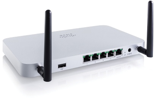
Figure 13-1 Cisco Meraki MX64W Wireless Router
Figure 13-2 shows a topology depicting the physical connection of a wired laptop to the wireless router, which is then connected to a cable or DSL modem for Internet connectivity.
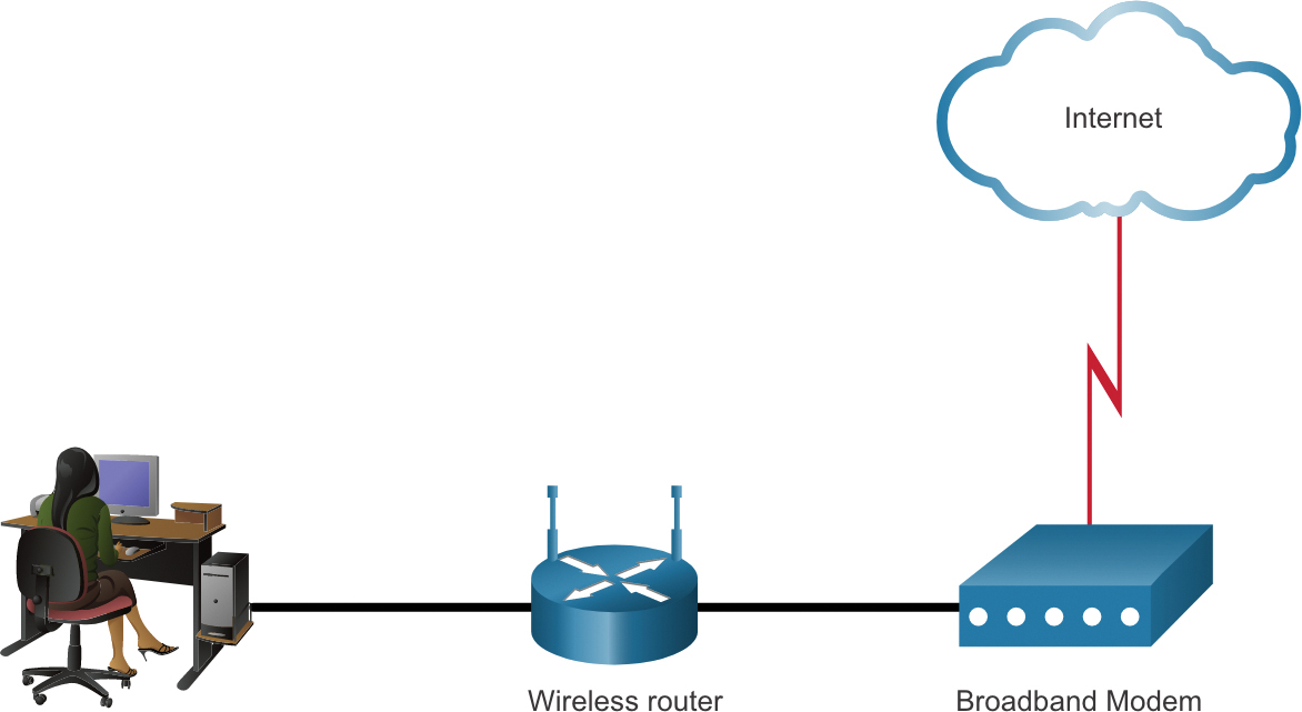
Figure 13-2 Wireless Router Connecting a WLAN to the Internet
These wireless routers typically provide WLAN security, dynamic host configuration protocol (DHCP) services, integrated Name Address Translation (NAT), quality of service (QoS), and a variety of other features. The feature set will vary based on the router model.
Note
Cable or DSL modem configuration is usually done by the service provider’s representative either onsite or remotely through a walkthrough with you on the phone. If you buy the modem, it comes with documentation for how to connect it to your service provider, which will most likely include contacting your service provider for more information.
Log in to the Wireless Router (13.1.3)
Most wireless routers are ready for service out of the box. They are preconfigured to be connected to the network and provide services. For example, the wireless router uses DHCP to automatically provide addressing information to connected devices. However, wireless router default IP addresses, usernames, and passwords can easily be found on the Internet. Just enter the search phrase “default wireless router IP address” or “default wireless router passwords” to see a listing of many websites that provide this information. For example, username and password for the wireless router in the figure is “admin”. Therefore, your first priority should be to change these defaults for security reasons.
To gain access to the wireless router’s configuration GUI, open a web browser. In the address field, enter the default IP address for your wireless router. The default IP address can be found in the documentation that came with the wireless router, or you can search the Internet. Figure 13-3 shows the IPv4 address 192.168.0.1, which is a common default for many manufacturers. A security window prompts for authorization to access the router GUI. The word admin is commonly used as the default username and password. Again, check your wireless router’s documentation or search the Internet.
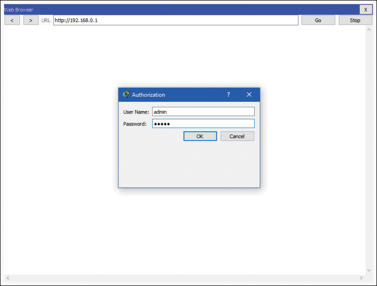
Figure 13-3 Connecting to a Wireless Router Using a Browser
Basic Network Setup (13.1.4)
Basic network setup includes the following steps:
![]()
Step 1. Log in to the router from a web browser. After logging in, a GUI opens, as shown in Figure 13-4. The GUI will have tabs or menus to help you navigate to various router configuration tasks. It is often necessary to save the settings changed in one window before proceeding to another window. At this point, it is a best practice to make changes to the default settings.

Figure 13-4 Basic Network Setup—Step 1
Step 2. Change the default administrative password. To change the default login password, find the administration portion of the router’s GUI. In this example, the Administration tab was selected. This is where the router password can be changed. On some devices, such as the one in Figure 13-5, you can change only the password. The username remains admin or whatever the default username is for the router you are configuring.
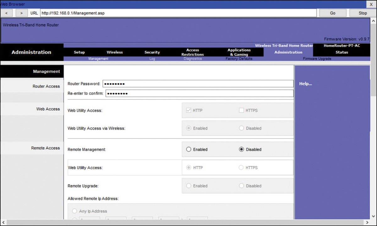
Figure 13-5 Basic Network Setup—Step 2
Step 3. Log in with the new administrative password. After you save the new password, the wireless router will request authorization again. Enter the username and new password, as shown in Figure 13-6.
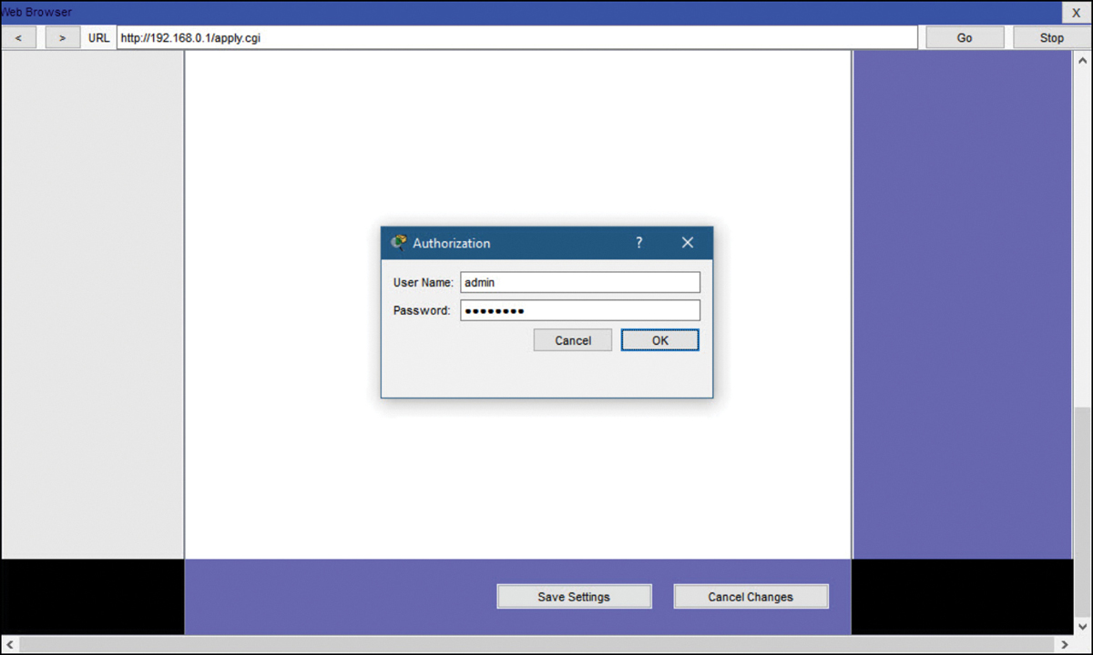
Figure 13-6 Basic Network Setup—Step 3
Step 4. Change the default DHCP IPv4 addresses. Change the default router IPv4 address. It is a best practice to use private IPv4 addressing inside your network. The IPv4 address 10.10.10.1 is used in Figure 13-7, but it could be any private IPv4 address you choose.

Figure 13-7 Basic Network Setup—Step 4
Step 5. Renew the IP address. When you click Save, you will temporarily lose access to the wireless router. Open a command window and renew your IP address with the ipconfig /renew command, as shown in Example 13-1.
Example 13-1 Basic Network Setup—Step 5
Packet Tracer PC Command Line 1.0
C:> ipconfig /renew

   IP Address......................: 10.10.10.100
   Subnet Mask.....................: 255.255.255.0
   Default Gateway.................: 10.10.10.1
   DNS Server......................: 0.0.0.0

C:>
Step 6. Log in to the router with the new IP address. Enter the router’s new IP address to regain access to the router configuration GUI, as shown in Figure 13-8. You are now ready to continue configuring the router for wireless access.

Figure 13-8 Basic Network Setup—Step 6
Basic Wireless Setup (13.1.5)
Basic wireless setup includes the following steps:
![]()
Step 1. View the WLAN defaults. Out of the box, a wireless router provides wireless access to devices using a default wireless network name and password. The network name is called the Service Set Identifier (SSID). Locate the basic wireless settings for your router to change these defaults, as shown in Figure 13-9.

Figure 13-9 Basic Wireless Setup—Step 1
Step 2. Change the network mode. Some wireless routers allow you to select which 802.11 standard to implement. Figure 13-10 shows that Legacy has been selected. This means wireless devices connecting to the wireless router can have a variety of wireless network interface cards (NICs) installed. Today’s wireless routers configured for legacy or mixed mode most likely support 802.11a, 802.11n, and 802.11ac NICs.

Figure 13-10 Basic Wireless Setup—Step 2
Step 3. Configure the SSID. Assign a SSID to the WLANs. OfficeNet is used in Figure 13-11 for all three WLANs (the third WLAN is not shown). The wireless router announces its presence by sending broadcasts advertising its SSID. This allows wireless hosts to automatically discover the name of the wireless network. If the SSID broadcast is disabled, you must manually enter the SSID on each wireless device that connects to the WLAN.
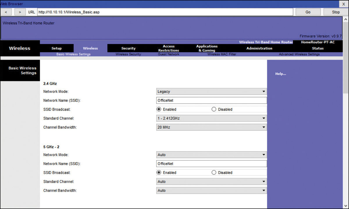
Figure 13-11 Basic Wireless Setup—Step 3
Step 4. Configure the channel. Devices configured with the same channel within the 2.4 GHz band may overlap and cause distortion, slowing down the wireless performance and potentially breaking network connections. The solution to avoid interference is to configure non-overlapping channels on the wireless routers and access points that are near to each other. Specifically, channels 1, 6, and 11 are non-overlapping. In Figure 13-12, the wireless router is configured to use channel 6.

Figure 13-12 Basic Wireless Setup—Step 4
Step 5. Configure the security mode. Out of the box, a wireless router may have no WLAN security configured. In Figure 13-13, the personal version of Wi-Fi Protected Access version 2 (WPA2 Personal) is selected for all three WLANs. WPA2 with Advanced Encryption Standard (AES) encryption is currently the strongest security mode.

Figure 13-13 Basic Wireless Setup—Step 5
Step 6. Configure the passphrase. WPA2 personal uses a passphrase to authenticate wireless clients, as shown in Figure 13-14. WPA2 Personal is easier to use in a small office or home environment because it does not require an authentication server. Larger organizations implement WPA2 enterprise and require wireless clients to authenticate with a username and password.

Figure 13-14 Basic Wireless Setup—Step 6
Configure a Wireless Mesh Network (13.1.6)
In a small office or home network, one wireless router may suffice to provide wireless access to all the clients. However, if you want to extend the range beyond approximately 45 meters indoors and 90 meters outdoors, you can add wireless access points. As shown in the wireless mesh network in Figure 13-15, two access points are configured with the same WLAN settings from our previous example. Notice that the channels selected are 1 and 11 so that the access points do not interfere with channel 6 configured previously on the wireless router.

Figure 13-15 Wireless Mesh Network with a Wireless Router and Two APs
Extending a WLAN in a small office or home has become increasingly easier. Manufacturers have made creating a wireless mesh network (WMN) simple through smartphone apps. You buy the system, disperse the access points, plug them in, download the app, and configure your WMN in a few steps. Search the Internet for “best wi-fi mesh network system” to find reviews of current offerings.
NAT for IPv4 (13.1.7)
On a wireless router, if you look for a page like the Status page shown in Figure 13-16, you will find the IPv4 addressing information that the router uses to send data to the Internet. Notice that the IPv4 address, 209.165.201.11, is a different network than the 10.10.10.1 address assigned to the router’s LAN interface. All the devices on the router’s LAN will get assigned addresses with the 10.10.10 prefix.

Figure 13-16 Verifying the Status of a Wireless Router
The 209.165.201.11 IPv4 address is publicly routable on the Internet. Any address with the 10 in the first octet is a private IPv4 address and cannot be routed on the Internet. Therefore, the router will use a process called Network Address Translation (NAT) to convert private IPv4 addresses to Internet-routable IPv4 addresses. With NAT, a private (local) source IPv4 address is translated to a public (global) address. The process is reversed for incoming packets. The router is able to translate many internal IPv4 addresses into public addresses by using NAT.
Some Internet service providers (ISPs) use private addressing to connect to customer devices. However, eventually your traffic will leave the provider’s network and be routed on the Internet. To see the IP addresses for your devices, search the Internet for “what is my IP address.” Do this for other devices on the same network and you will see that they all share the same public IPv4 address. NAT makes this possible by tracking the source port numbers for every session established by a device. If your ISP has IPv6 enabled, you will see a unique IPv6 address for each device.
Quality of Service (13.1.8)
Many wireless routers have an option for configuring Quality of Service (QoS). By configuring QoS, you can guarantee that certain traffic types, such as voice and video, are prioritized over traffic that is not as time-sensitive, such as email and web browsing. On some wireless routers, traffic can also be prioritized on specific ports.
Figure 13-17 is a simplified mockup of a QoS interface based on a Netgear GUI. You will usually find the QoS settings in the advanced menus. If you have a wireless router available, investigate the QoS settings. Sometimes, these might be listed under “bandwidth control” or something similar. Consult the wireless router’s documentation or search the Internet for “qos settings” for your router’s make and model.
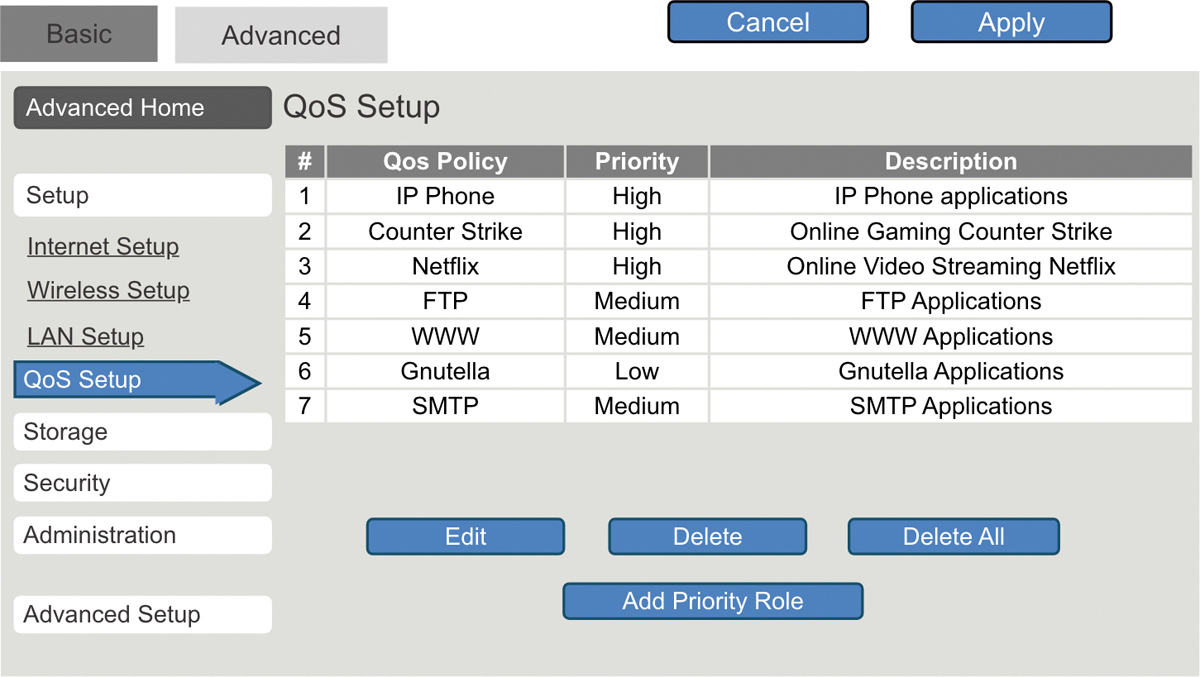
Figure 13-17 QoS Settings on a Wireless Router
Port Forwarding (13.1.9)
Wireless routers typically block TCP and UDP ports to prevent unauthorized access in and out of a LAN. However, there are situations when specific ports must be opened so that certain programs and applications can communicate with devices on different networks. Port forwarding is a rule-based method of directing traffic between devices on separate networks.
When traffic reaches the router, the router determines if the traffic should be forwarded to a certain device based on the port number found with the traffic. For example, a router might be configured to forward port 80, which is associated with HTTP. When the router receives a packet with the destination port of 80, the router forwards the traffic to the server inside the network that serves web pages. In Figure 13-18, port forwarding is enabled for port 80 and is associated with the web server at IPv4 address 10.10.10.50.
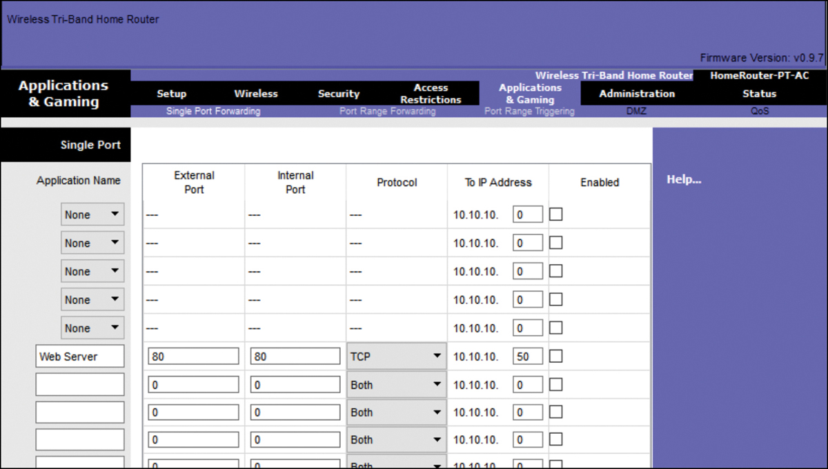
Figure 13-18 Configuring Port Forwarding on a Wireless Router
Port triggering allows the router to temporarily forward data through inbound ports to a specific device. You can use port triggering to forward data to a computer only when a designated port range is used to make an outbound request. For example, a video game might use ports 27000 to 27100 for connecting with other players. These are the trigger ports. A chat client might use port 56 for connecting the same players so that they can interact with each other. In this instance, if there is gaming traffic on an outbound port within the triggered port range, inbound chat traffic on port 56 is forwarded to the computer that is being used to play the video game and chat with friends. When the game is over and the triggered ports are no longer in use, port 56 is no longer allowed to send traffic of any type to this computer.
Packet Tracer—Configure a Wireless Network (13.1.10)
![]()
In this activity, you configure a wireless router and an access point to accept wireless clients and route IP packets.
Lab—Configure a Wireless Network (13.1.11)
![]()
In this lab, you configure basic settings on a wireless router and connect a PC to a router wirelessly.
Configure a Basic WLAN on the WLC (13.2)
In this section, you learn how to configure a Wireless LAN Controller (WLC) WLAN to use the management interface and WPA2 pre-shared key (PSK) authentication.
Video—Configure a Basic WLAN on the WLC (13.2.1)
![]()
Refer to the online course to view this video.
WLC Topology (13.2.2)
The topology and addressing scheme used for the videos and this section are shown in Figure 13-19 and Table 13-1. The access point (AP) is a controller-based AP, as opposed to an autonomous AP. Recall that controller-based APs require no initial configuration and are often called lightweight APs (LAPs). LAPs use the Lightweight Access Point Protocol (LWAPP) to communicate with a WLAN controller (WLC). Controller-based APs are useful in situations where many APs are required in the network. As more APs are added, each AP is automatically configured and managed by the WLC.
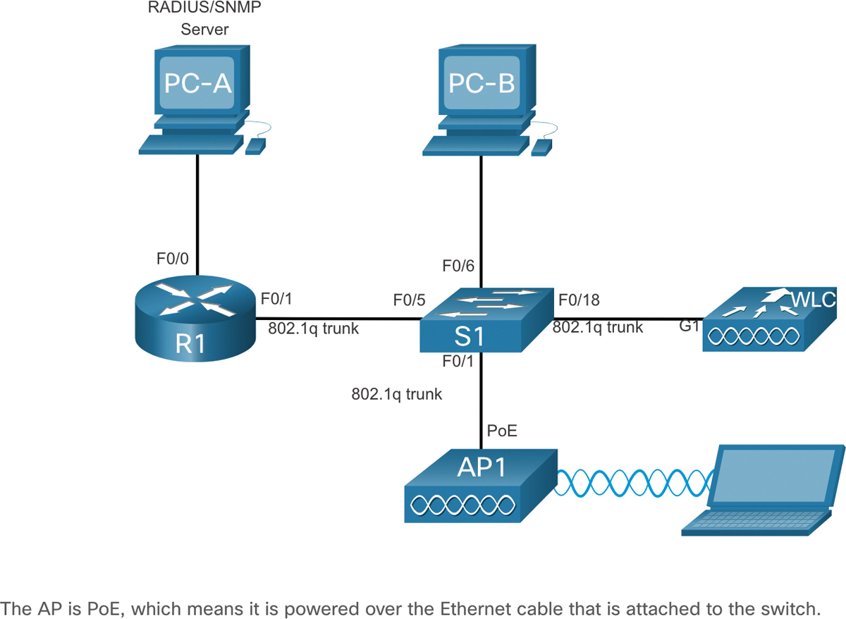
Figure 13-19 WLC Reference Topology
Table 13-1 Addressing Table
Device |
Interface |
IP Address |
Subnet Mask |
R1 |
F0/0 |
172.16.1.1 |
255.255.255.0 |
R1 |
F0/1.1 |
192.168.200.1 |
255.255.255.0 |
S1 |
VLAN 1 |
DHCP |
|
WLC |
Management |
192.168.200.254 |
255.255.255.0 |
AP1 |
Wired 0 |
192.168.200.3 |
255.255.255.0 |
PC-A |
NIC |
172.16.1.254 |
255.255.255.0 |
PC-B |
NIC |
DHCP |
|
Wireless Laptop |
NIC |
DHCP |
Log in to the WLC (13.2.3)
Configuring a wireless LAN controller (WLC) is not that much different from configuring a wireless router. The big difference is that a WLC controls APs and provides more services and management capabilities, many of which are beyond the scope of this module.
Note
The figures in this section and the next that show the graphical user interface (GUI) and menus are from a Cisco 3504 Wireless Controller. However, other WLC models will have similar menus and features.
Figure 13-20 shows the user logging in to the WLC with credentials that were configured during initial setup.
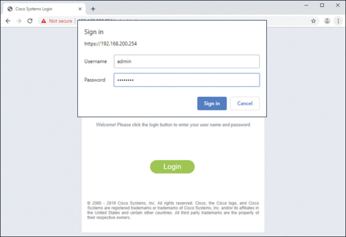
Figure 13-20 Logging In to the WLC
The Network Summary page is a dashboard that provides a quick overview of the number of configured wireless networks, associated access points (APs), and active clients. You can also see the number of rogue access points and clients, as shown in Figure 13-21.

Figure 13-21 WLC Network Summary Dashboard
View AP Information (13.2.4)
Click Access Points from the left menu to view an overall picture of the AP’s system information and performance, as shown in Figure 13-22. The AP is using IP address 192.168.200.3. Because Cisco Discovery Protocol (CDP) is active on this network, the WLC knows that the AP is connected to the FastEthernet 0/1 port on the switch.
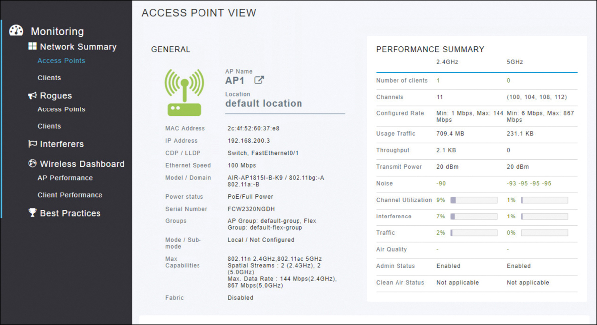
Figure 13-22 Access Point View Page
This AP in the topology is a Cisco Aironet 1815i, which means you can use the command line and a limited set of familiar IOS commands. In Example 13-2, the network administrator pinged the default gateway, pinged the WLC, and verified the wired interface.
Example 13-2 Verifying AP Has Connectivity
AP1# ping 192.168.200.1
Sending 5, 100-byte ICMP Echos to 192.168.200.1, timeout is 2 seconds
!!!!!
Success rate is 100 percent (5/5), round-trip min/avg/max = 1069812.242/
  1071814.785/1073817.215 ms
AP1#
AP1# ping 192.168.200.254
Sending 5, 100-byte ICMP Echos to 192.168.200.254, timeout is 2 seconds
!!!!!
Success rate is 100 percent (5/5), round-trip min/avg/max = 1055820.953/
  1057820.738/1059819.928 ms
AP1#
AP1# show interface wired 0
wired0    Link encap:Ethernet  HWaddr 2C:4F:52:60:37:E8
          inet addr:192.168.200.3  Bcast:192.168.200.255  Mask:255.255.255.255
          UP BROADCAST RUNNING PROMISC MULTICAST  MTU:1500  Metric:1
          RX packets:2478 errors:0 dropped:3 overruns:0 frame:0
          TX packets:1494 errors:0 dropped:0 overruns:0 carrier:0
          collisions:0 txqueuelen:80
          RX bytes:207632 (202.7 KiB)  TX bytes:300872 (293.8 KiB)
AP1#
Advanced Settings (13.2.5)
Most WLC will come with some basic settings and menus that users can quickly access to implement a variety of common configurations. However, as a network administrator, you will typically access the advanced settings. For the Cisco 3504 Wireless Controller, click Advanced in the upper-right corner to access the advanced Summary page, as shown in Figure 13-23. From here, you can access all the features of the WLC.
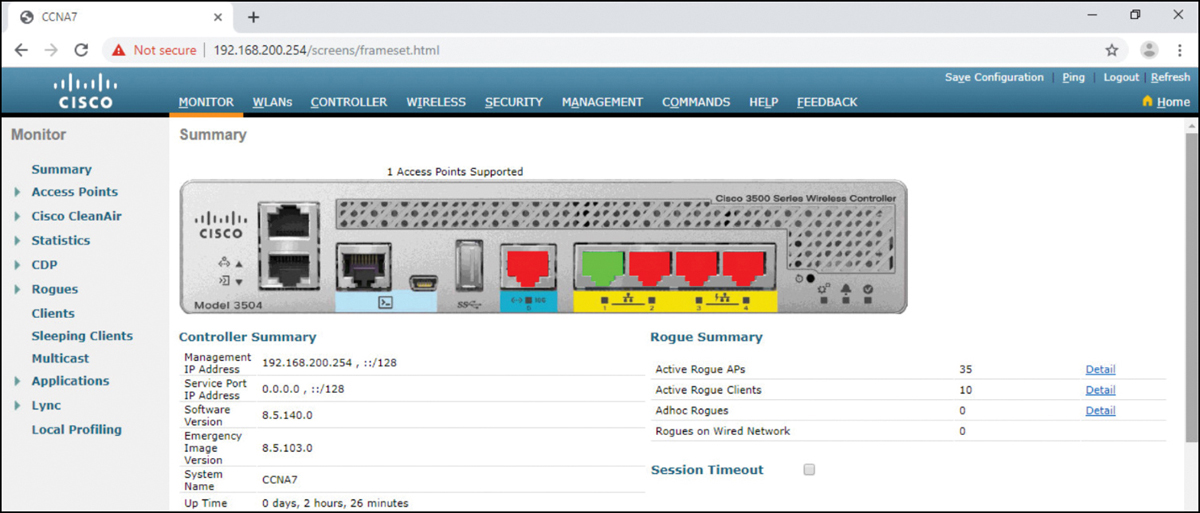
Figure 13-23 Viewing the Summary Page of Advanced Settings
Configure a WLAN (13.2.6)
Wireless LAN Controllers have ports and interfaces. Ports are the sockets for the physical connections to the wired network. They resemble switch ports. Interfaces are virtual. They are created in software and are very similar to VLAN interfaces. In fact, each interface that will carry traffic from a WLAN is configured on the WLC as a different VLAN.
The Cisco 3504 WLC can support 150 access points and 4096 VLANs; however, it has only five physical ports, as shown in Figure 13-24. This means that each physical port can support many APs and WLANs. The ports on the WLC are essentially trunk ports that can carry traffic from multiple VLANs to a switch for distribution to multiple APs. Each AP can support multiple WLANs.
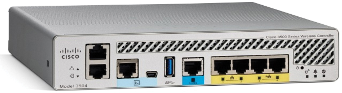
Figure 13-24 Backplane of a Cisco 3504 WLC
Basic WLAN configuration on the WLC includes the following steps:
![]()
Step 1. Create the WLAN. In Figure 13-25, the administrator is creating a new WLAN that will use Wireless_LAN as the name and service set identifier (SSID). The ID is an arbitrary value that is used to identify the WLAN in display output on the WLC.
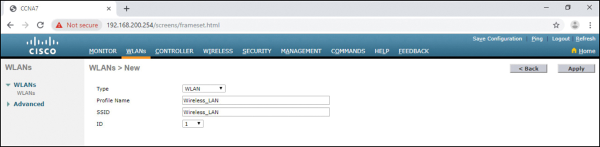
Figure 13-25 Configure a WLAN—Step 1
Step 2. Apply and Enable the WLAN. After clicking Apply, the network administrator must enable the WLAN before it can be accessed by users, as shown in Figure 13-26. The Enable check box allows the network administrator to configure a variety of features for the WLAN, as well as additional WLANs, before enabling them for wireless client access. From here, the network administrator can configure a variety of settings for the WLAN, including security, QoS, policies, and other advanced settings.
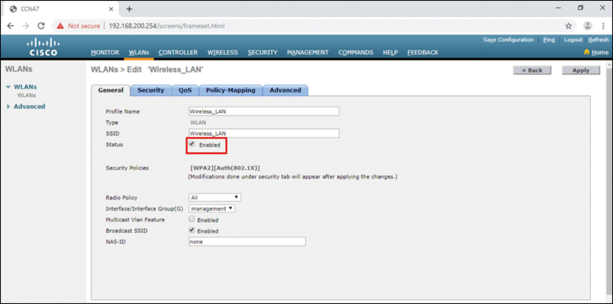
Figure 13-26 Configure a WLAN—Step 2
Step 3. Select the Interface. When you create a WLAN, you must select the interface that will carry the WLAN traffic. Figure 13-27 shows the selection of an interface that has already been created on the WLC. You learn how to create interfaces later in this module.

Figure 13-27 Configure a WLAN—Step 3
Step 4. Secure the WLAN. Click the Security tab to access all the available options for securing the LAN. The network administrator wants to secure Layer 2 with WPA2-PSK. WPA2 and 802.1X are set by default. In the Layer 2 Security drop-down box, verify that WPA+WPA2 is selected (not shown). Click PSK and enter the pre-shared key, as shown Figure 13-28. Then click Apply. This will enable the WLAN with WPA2-PSK authentication. Wireless clients that know the pre-shared key can now associate and authenticate with the AP.

Figure 13-28 Configure a WLAN—Step 4
Step 5. Verify the WLAN is operational. Click WLANs in the menu on the left to view the newly configured WLAN. In Figure 13-29, you can verify that WLAN ID 1 is configured with Wireless_LAN as the name and SSID; it is enabled and is using WPA2 PSK security.
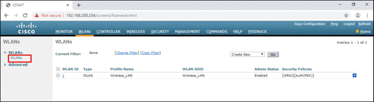
Figure 13-29 Configure a WLAN—Step 5
Step 6. Monitor the WLAN. Click the MONITOR tab at the top to access the advanced Summary page again. Here you can see that the Wireless_LAN now has one client using its services, as shown in Figure 13-30.

Figure 13-30 Configure a WLAN—Step 6
Step 7. View Wireless Client Details. Click Clients in the left menu to view more information about the clients connected to the WLAN, as shown in Figure 13-31. One client is attached to Wireless_LAN through AP1 and was given the IP address 192.168.5.2. DHCP services in this topology are provided by the router.

Figure 13-31 View Wireless Client Details
Packet Tracer—Configure a Basic WLAN on the WLC (13.2.7)
![]()
In this lab, you explore some of the features of a wireless LAN controller. You create a new WLAN on the controller and implement security on that LAN. Then you configure a wireless host to connect to the new WLAN through an AP that is under the control of the WLC. Finally, you verify connectivity.
Configure a WPA2 Enterprise WLAN on the WLC (13.3)
In this section, you learn how to configure a WLC WLAN to use a VLAN interface, a DHCP server, and WPA2 Enterprise authentication.
Video—Define an SNMP and RADIUS Server on the WLC (13.3.1)
![]()
Refer to the online course to view this video.
SNMP and RADIUS (13.3.2)
In Figure 13-32, PC-A is running Simple Network Management Protocol (SNMP) and Remote Authentication Dial-In User Service (RADIUS) server software. SNMP is used to monitor the network. The network administrator wants the WLC to forward all SNMP log messages, called traps, to the SNMP server.

Figure 13-32 WLC Reference Topology
In addition, for WLAN user authentication, the network administrator wants to use a RADIUS server for authentication, authorization, and accounting (AAA) services. Instead of entering a publicly known pre-shared key to authenticate, as they do with WPA2-PSK, users will enter their own username and password credentials. The credentials will be verified by the RADIUS server. This way, individual user access can be tracked and audited if necessary, and user accounts can be added or modified from a central location. The RADIUS server is required for WLANs that are using WPA2 Enterprise authentication.
Note
SNMP server and RADIUS server configuration is beyond the scope of this module.
Configure SNMP Server Information (13.3.3)
Click the MANAGEMENT tab to access a variety of management features. SNMP is listed at the top of the menu on the left. Click SNMP to expand the submenus, and then click Trap Receivers. Click New to configure a new SNMP trap receiver, as shown in Figure 13-33.
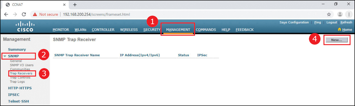
Figure 13-33 Creating a New SNMP Trap Receiver
Enter the SNMP Community name and the IP address (IPv4 or IPv6) for the SNMP server. Click Apply. The WLC will now forward SNMP log messages to the SNMP server, as shown in Figure 13-34.
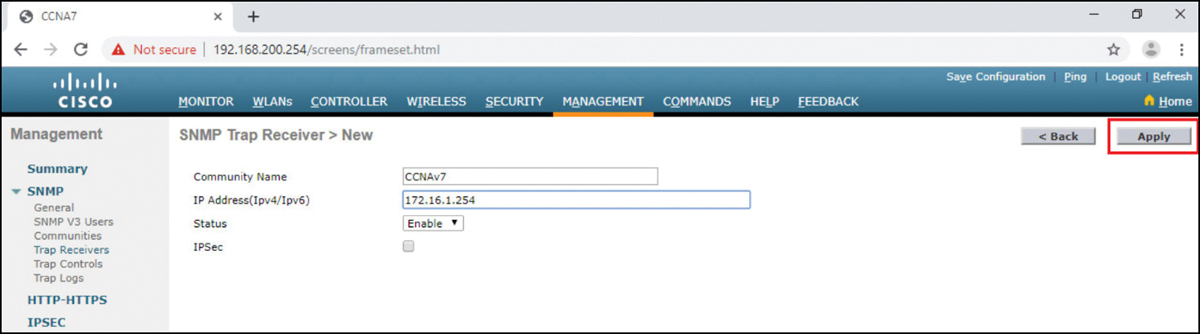
Figure 13-34 Configuring the SNMP Community Name and IPv4 Address
Configure RADIUS Server Information (13.3.4)
In our example configuration, the network administrator wants to configure a WLAN using WPA2 Enterprise, as opposed to WPA2 Personal or WPA2 PSK. Authentication will be handled by the RADIUS server running on PC-A.
To configure the WLC with the RADIUS server information, click the SECURITY tab, RADIUS, Authentication. No RADIUS servers are currently configured. Click New to add PC-A as the RADIUS server, as shown in Figure 13-35.
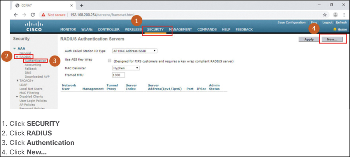
Figure 13-35 Creating a New RADIUS Server
Enter the IPv4 address for PC-A and the shared secret. This is the password used between the WLC and the RADIUS server. It is not for users. Click Apply, as shown in Figure 13-36.

Figure 13-36 Configuring RADIUS Server Information
After clicking Apply, the list of configured RADIUS Authentication Servers refreshes with the new server listed, as shown in Figure 13-37.

Figure 13-37 Verifying the RADIUS Server Configuration
Video—Configure a VLAN for a New WLAN (13.3.5)
![]()
Refer to the online course to view this video.
Topology with VLAN 5 Addressing (13.3.6)
Each WLAN configured on the WLC needs its own virtual interface. The WLC has five physical ports for data traffic. Each physical port can be configured to support multiple WLANs, each on its own virtual interface. Physical ports can also be aggregated to create high-bandwidth links.
The network administrator has decided that the new WLAN will use interface VLAN 5 and network 192.168.5.0/24. R1 already has a subinterface configured and active for VLAN 5, as shown in Figure 13-38 and the show ip interface brief output in Example 13-3.
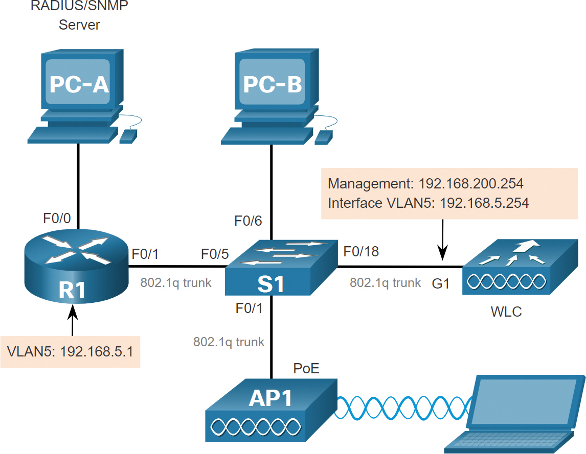
Figure 13-38 WLC Reference Topology
Example 13-3 Verifying VLAN 5 Interface on R1
R1# show ip interface brief
Interface              IP-Address      OK? Method Status                Protocol
FastEthernet0/0        172.16.1.1      YES manual up                    up
FastEthernet0/1        unassigned      YES unset  up                    up
FastEthernet0/1.1      192.168.200.1   YES manual up                    up
FastEthernet0/1.5      192.168.5.254   YES manual up                    up
(output omitted)
R1#
Configure a New Interface (13.3.7)
VLAN interface configuration on the WLC includes the following steps:
![]()
Step 1. Create a new interface. To add a new interface, click CONTROLLER, Interfaces, New, as shown in Figure 13-39.
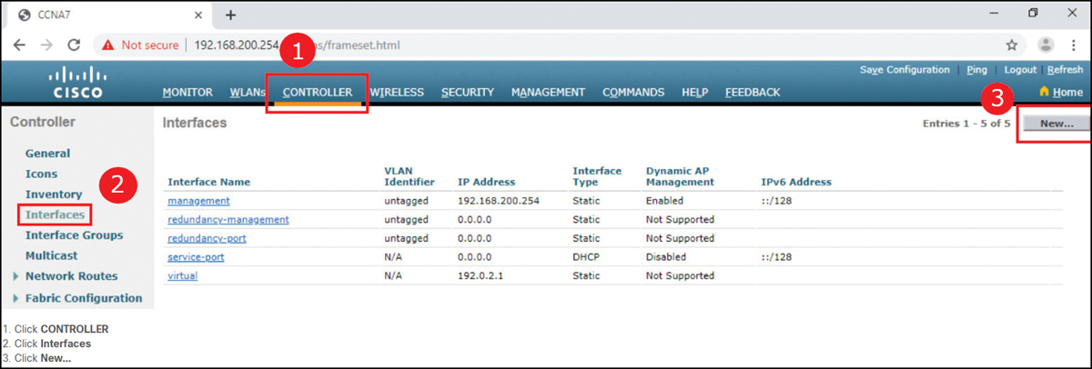
Figure 13-39 Configure a New Interface—Step 1
Step 2. Configure the VLAN name and ID. In Figure 13-40, the network administrator configures the interface name as vlan5 and the VLAN ID as 5. Clicking Apply will create the new interface.
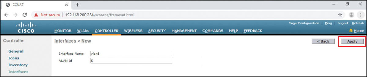
Figure 13-40 Configure a New Interface—Step 2
Step 3. Configure the port and interface address. On the Edit page for the interface, configure the physical port number. G1 in the topology is Port Number 1 on the WLC. Then configure the VLAN 5 interface addressing. In Figure 13-41, VLAN 5 is assigned IPv4 address 192.168.5.254/24. R1 is the default gateway at IPv4 address 192.168.5.1.

Figure 13-41 Configure a New Interface—Step 3
Step 4. Configure the DHCP server address. In larger enterprises, WLCs will be configured to forward DHCP messages to a dedicated DHCP server. Scroll down the page to configure the primary DHCP server as IPv4 address 192.168.5.1, as shown in Figure 13-42. This is the default gateway router address. The router is configured with a DHCP pool for the WLAN network. As hosts join the WLAN that is associated with the VLAN 5 interface, they will receive addressing information from this pool.
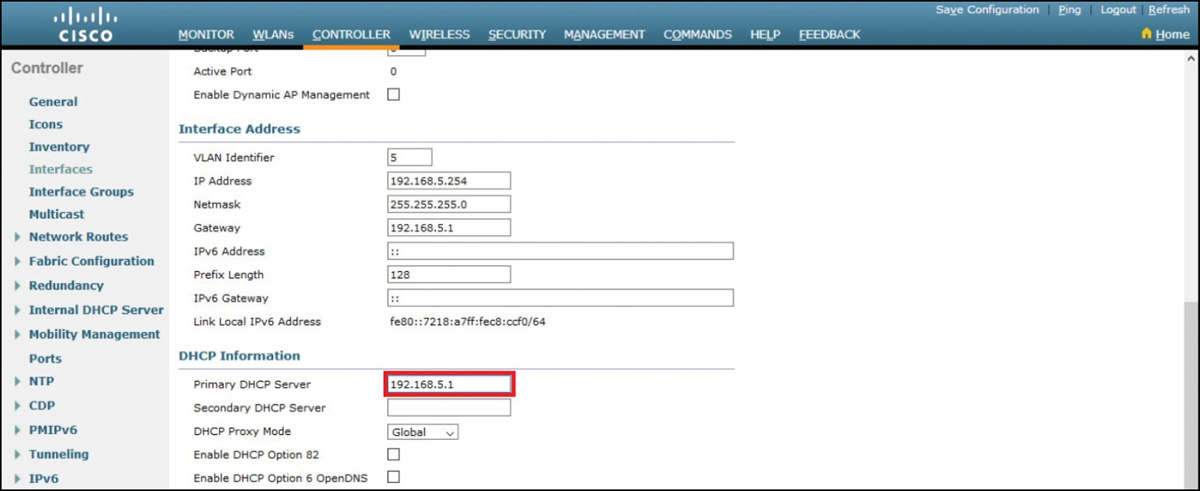
Figure 13-42 Configure a New Interface—Step 4
Step 5. Apply and Confirm. Scroll to the top and click Apply, as shown in Figure 13-43. Click OK for the warning message.

Figure 13-43 Configure a New Interface—Step 5
Step 6. Verify Interfaces. Click Interfaces. The new vlan5 interface is now shown in the list of interfaces with its IPv4 address, as shown in Figure 13-44.
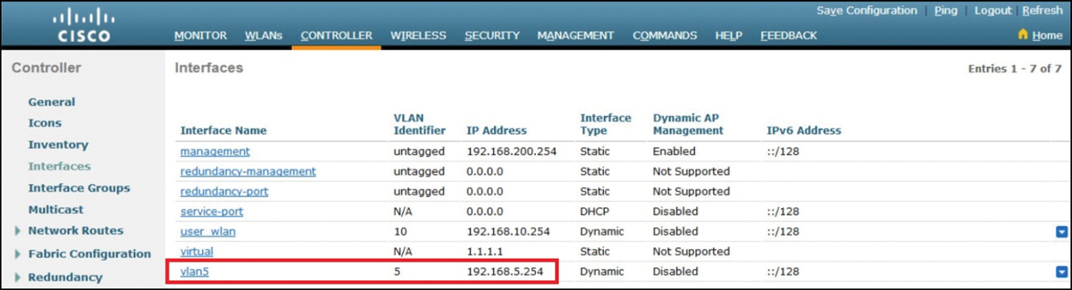
Figure 13-44 Configure a New Interface—Step 6
Video—Configure a DHCP Scope (13.3.8)
![]()
Refer to the online course to view this video.
Configure a DHCP Scope (13.3.9)
DHCP scope configuration includes the following steps:
![]()
Step 1. Create a new DHCP scope. A DHCP scope is very similar to a DHCP pool on a router. It can include a variety of information, including a pool of addresses to assign to DHCP clients, DNS server information, lease times, and more. To configure a new DHCP scope, click Internal DHCP Server, DHCP Scope, New, as shown in Figure 13-45.
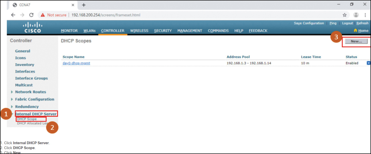
Figure 13-45 Configure a DHCP Scope—Step 1
Step 2. Name the DHCP scope. On the next screen, name the scope, as shown in Figure 13-46. Because this scope will apply to the wireless management network, the network administrator uses Wireless_Management as the Scope Name and clicks Apply.

Figure 13-46 Configure a DHCP Scope—Step 2
Step 3. Verify the new DHCP scope. You are returned to the DHCP Scopes page and can verify the scope is ready to be configured, as shown in Figure 13-47. Click the new scope name to configure the DHCP scope.
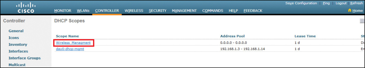
Figure 13-47 Configure a DHCP Scope—Step 3
Step 4. Configure and enable the new DHCP scope. On the Edit screen for the Wireless_Management scope, configure a pool of addresses for the 192.168.200.0/24 network starting at .240 and ending at .249. The network address and subnet mask are configured. The default router IPv4 address is configured, which is the subinterface for R1 at 192.168.200.1. For this example, in Figure 13-48, the rest of the scope is left unchanged. The network administrator selects Enabled from the Status drop down and clicks Apply.
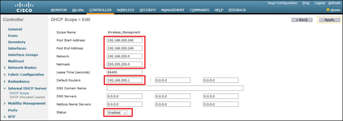
Figure 13-48 Configure a DHCP Scope—Step 4
Step 5. Verify the enable DHCP scope. The network administrator is returned to the DHCP Scopes page and can verify the scope is ready to be allocated to a new WLAN, as shown in Figure 13-49.

Figure 13-49 Configure a DHCP Scope—Step 5
Video—Configure a WPA2 Enterprise WLAN (13.3.10)
![]()
Refer to the online course to view this video.
Configure a WPA2 Enterprise WLAN (13.3.11)
By default, all newly created WLANs on the WLC will use WPA2 with Advanced Encryption System (AES). 802.1X is the default key management protocol used to communicate with the RADIUS server. Because the network administrator already configured the WLC with the IPv4 address of the RADIUS server running on PC-A, the only configuration left to do is to create a new WLAN to use interface vlan5.
![]()
Step 1. Create a new WLAN. Click the WLANs tab and then Go to create a new WLAN, as shown in Figure 13-50.

Figure 13-50 Configure a WPA2 Enterprise WLAN—Step 1
Step 2. Configure the WLAN name and SSID. Fill in the profile name and SSID. To be consistent with the VLAN that was previously configured, choose an ID of 5. However, any available value can be used. Click Apply to create the new WLAN, as shown in Figure 13-51.
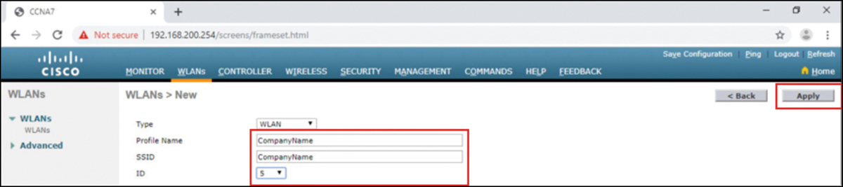
Figure 13-51 Configure a WPA2 Enterprise WLAN—Step 2
Step 3. Enable the WLAN for VLAN 5. The WLAN is created but it still needs to be enabled and associated with the correct VLAN interface. Change the status to Enabled and choose vlan5 from the Interface/Interface Group(G) drop-down list. Click Apply, and click OK to accept the popup message, as shown in Figure 13-52.
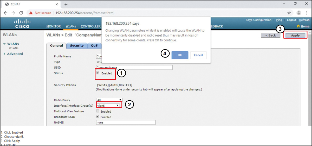
Figure 13-52 Configure a WPA2 Enterprise WLAN—Step 3
Step 4. Verify AES and 802.1X defaults. Click the Security tab to view the default security configuration for the new WLAN, as shown in Figure 13-53. The WLAN will use WPA2 security with AES encryption. Authentication traffic is handled by 802.1X between the WLC and the RADIUS server.

Figure 13-53 Configure a WPA2 Enterprise WLAN—Step 4
Step 5. Configure the RADIUS server. You now need to select the RADIUS server that will be used to authenticate users for this WLAN. Click the AAA Servers tab. In the drop-down box select the RADIUS server that was configured on the WLC previously. Apply your changes, as shown in Figure 13-54.
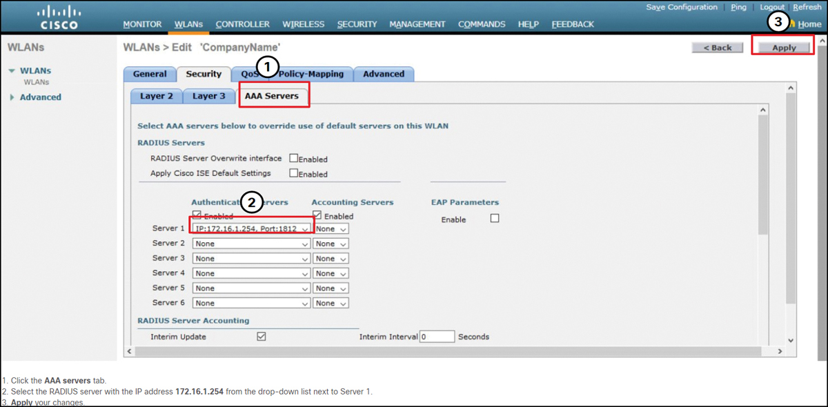
Figure 13-54 Configure a WPA2 Enterprise WLAN—Step 5
Step 6. Verify that the new WLAN is available. To verify the new WLAN is listed and enabled, click Back or the WLANs submenu on the left. Both the Wireless_LAN WLAN and the CompanyName WLAN are listed. In Figure 13-55, notice that both are enabled. Wireless_LAN is using WPA2 with PSK authentication. CompanyName is using WPA2 security with 802.1X authentication.
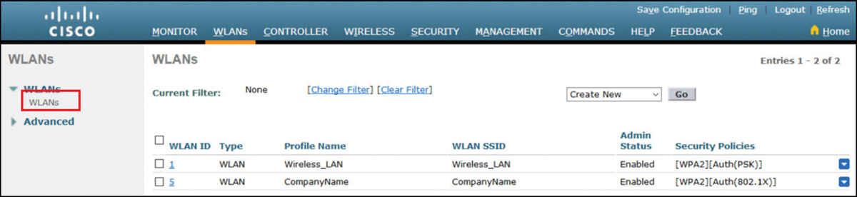
Figure 13-55 Configure a WPA2 Enterprise WLAN—Step 6
Packet Tracer—Configure a WPA2 Enterprise WLAN on the WLC (13.3.12)
![]()
In this activity, you configure a new WLAN on a wireless LAN controller (WLC), including the VLAN interface that it will use. You configure the WLAN to use a RADIUS server and WPA2-Enterprise to authenticate users. You also configure the WLC to use an SNMP server.
Troubleshoot WLAN Issues (13.4)
In this section, you learn how to troubleshoot common wireless configuration issues.
Troubleshooting Approaches (13.4.1)
In the previous sections, you learned about WLAN configuration. Here we discuss troubleshooting WLAN issues.
Network problems can be simple or complex and can result from a combination of hardware, software, and connectivity issues. Technicians must be able to analyze the problem and determine the cause of the error before they can resolve the network issue. This process is called troubleshooting.
Troubleshooting any sort of network problem should follow a systematic approach. A common and efficient troubleshooting methodology is based on the scientific method and can be broken into the six main steps shown in Table 13-2.
Table 13-2 Six Steps for Troubleshooting
Step |
Title |
Description |
1 |
Identify the Problem |
The first step in the troubleshooting process is to identify the problem. Although tools can be used in this step, a conversation with the user is often very helpful. |
2 |
Establish a Theory of Probable Causes |
After you have talked to the user and identified the problem, you can try to establish a theory of probable causes. This step often yields more than a few probable causes to the problem. |
3 |
Test the Theory to Determine Cause |
Based on the probable causes, test your theories to determine which one is the cause of the problem. A technician will often apply a quick procedure to test to see if it solves the problem. If a quick procedure does not correct the problem, you might need to research the problem further to establish the exact cause. |
4 |
Establish a Plan of Action to Resolve the Problem and Implement the Solution |
After you have determined the exact cause of the problem, establish a plan of action to resolve the problem and implement the solution. |
5 |
Verify Full System Functionality and Implement Preventive Measures |
After you have corrected the problem, verify full functionality and, if applicable, implement preventive measures. |
6 |
Document Findings, Actions, and Outcomes |
In the final step of the troubleshooting process, document your findings, actions, and outcomes. This is very important for future reference. |
To assess the problem, determine how many devices on the network are experiencing the problem. If there is a problem with one device on the network, start the troubleshooting process at that device. If there is a problem with all devices on the network, start the troubleshooting process at the device where all other devices are connected. You should develop a logical and consistent method for diagnosing network problems by eliminating one problem at a time.
Wireless Client Not Connecting (13.4.2)
When troubleshooting a WLAN, a process of elimination is recommended.
In Figure 13-56, a wireless client is not connecting to the WLAN.
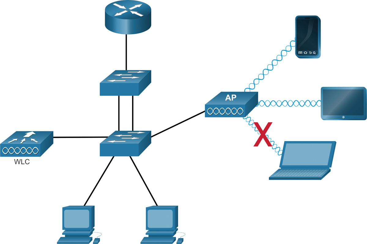
Figure 13-56 WLC Reference Topology with a Client Connectivity Issue
If there is no connectivity, check the following:
Confirm the network configuration on the PC using the ipconfig command. Verify that the PC has received an IP address via DHCP or is configured with a static IP address.
Confirm that the device can connect to the wired network. Connect the device to the wired LAN and ping a known IP address.
If necessary, reload drivers as appropriate for the client. It may be necessary to try a different wireless NIC.
If the wireless NIC of the client is working, check the security mode and encryption settings on the client. If the security settings do not match, the client cannot gain access to the WLAN.
If the PC is operational but the wireless connection is performing poorly, check the following:
How far is the PC from an AP? Is the PC out of the planned coverage area (BSA)?
Check the channel settings on the wireless client. The client software should detect the appropriate channel as long as the SSID is correct.
Check for the presence of other devices in the area that may be interfering with the 2.4 GHz band. Examples of other devices are cordless phones, baby monitors, microwave ovens, wireless security systems, and potentially rogue APs. Data from these devices can cause interference in the WLAN and intermittent connection problems between a wireless client and AP.
Next, ensure that all the devices are actually in place. Consider a possible physical security issue. Is there power to all devices and are they powered on?
Finally, inspect links between cabled devices looking for bad connectors or damaged or missing cables. If the physical plant is in place, verify the wired LAN by pinging devices, including the AP. If connectivity still fails at this point, perhaps something is wrong with the AP or its configuration.
When the user PC is eliminated as the source of the problem, and the physical status of devices is confirmed, begin investigating the performance of the AP. Check the power status of the AP.
Troubleshooting When the Network Is Slow (13.4.3)
To optimize and increase the bandwidth of 802.11 dual-band routers and APs, either
Upgrade your wireless clients: Older 802.11b, 802.11g, and even 802.11n devices can slow the entire WLAN. For the best performance, all wireless devices should support the same highest acceptable standard. Although 802.11ax was released in 2019, 802.11ac is most likely the highest standard that enterprises can currently enforce.
Split the traffic: The easiest way to improve wireless performance is to split the wireless traffic between the 802.11n 2.4 GHz band and the 5 GHz band. Therefore, 802.11n (or better) can use the two bands as two separate wireless networks to help manage the traffic. For example, use the 2.4 GHz network for basic Internet tasks, such as web browsing, email, and downloads, and use the 5 GHz band for streaming multimedia, as shown in Figure 13-57.
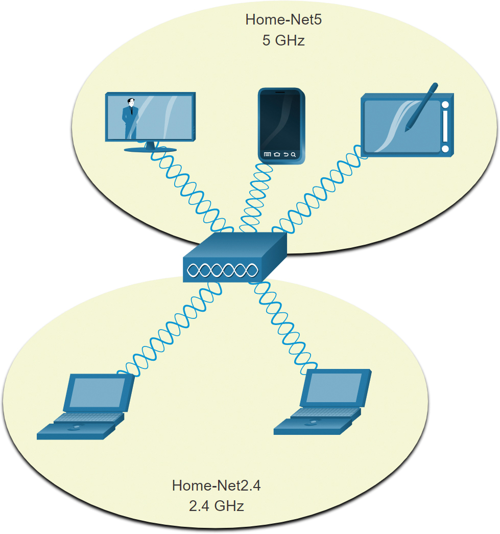
Figure 13-57 AP with Traffic Split Between 2.4 GHz and 5 GHz Band
There are several reasons for using a split-the-traffic approach:
The 2.4 GHz band may be suitable for basic Internet traffic that is not time-sensitive.
The bandwidth may still be shared with other nearby WLANs.
The 5 GHz band is much less crowded than the 2.4 GHz band; ideal for streaming multimedia.
The 5 GHz band has more channels; therefore, the channel chosen is likely interference-free.
By default, dual-band routers and APs use the same network name on both the 2.4 GHz band and the 5 GHz band. The simplest way to segment traffic is to rename one of the wireless networks. With a separate, descriptive name, it is easier to connect to the right network.
To improve the range of a wireless network, ensure the wireless router or AP location is free of obstructions, such as furniture, fixtures, and tall appliances. These block the signal, which shortens the range of the WLAN. If this still does not solve the problem, a Wi-Fi Range Extender or deploying the Powerline wireless technology may be used.
Updating Firmware (13.4.4)
Most wireless routers and APs offer upgradable firmware. Firmware releases may contain fixes for common problems reported by customers as well as security vulnerabilities. You should periodically check the router or AP for updated firmware. In Figure 13-58, the network administrator is verifying that the firmware is up to date on a Cisco Meraki AP.
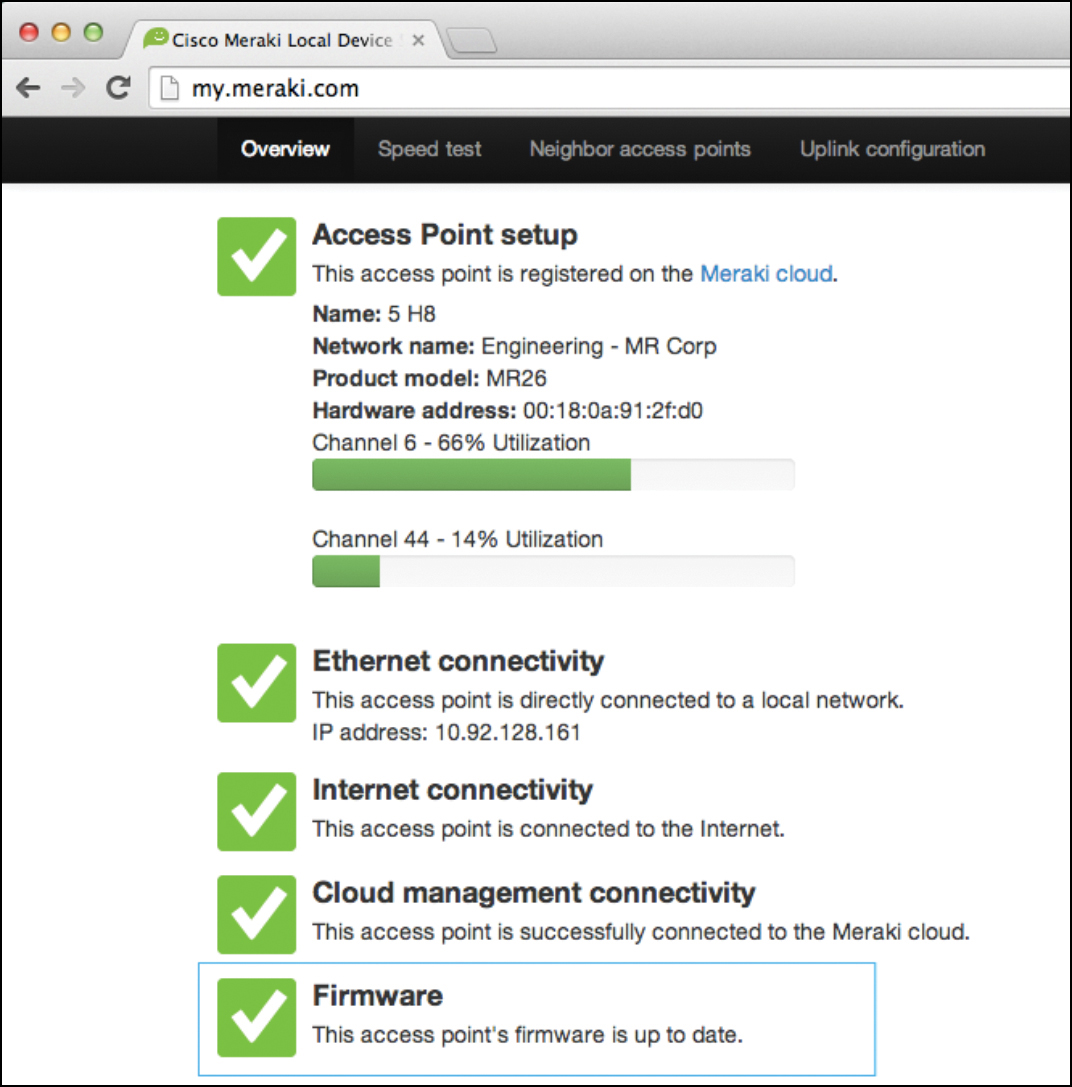
Figure 13-58 Verifying Firmware on a Cisco Meraki AP
On a WLC, there will most likely be the ability to upgrade the firmware on all APs that the WLC controls. In Figure 13-59, the network administrator is downloading the firmware image that will be used to upgrade all the APs.
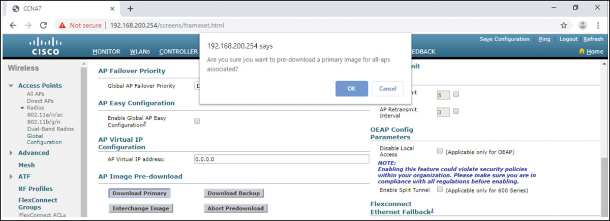
Figure 13-59 Firmware Download on the Cisco 3504 WLC
Users will be disconnected from the WLAN and the Internet until the upgrade finishes. The wireless router may need to reboot several times before normal network operations are restored.
Packet Tracer—Troubleshoot WLAN Issues (13.4.5)
![]()
Now that you have learned how to configure wireless in home and enterprise networks, you need to learn how to troubleshoot in both wireless environments. Your goal is to enable connectivity between hosts on the networks to the Web Server by both IP address and URL. Connectivity between the home and enterprise networks is not required.
Summary (13.5)
Remote workers, small branch offices, and home networks often use a wireless router, which typically includes a switch for wired clients, a port for an Internet connection (sometimes labeled “WAN”), and wireless components for wireless client access. Most wireless routers are preconfigured to be connected to the network and provide services. The wireless router uses DHCP to automatically provide addressing information to connected devices. Your first priority should be to change the username and password of your wireless router. Use your router’s interface to complete basic network and wireless setup. If you want to extend the range beyond approximately 45 meters indoors and 90 meters outdoors, you can add wireless access points. The router will use a process called Network Address Translation (NAT) to convert private IPv4 addresses to Internet-routable IPv4 addresses. By configuring QoS, you can guarantee that certain traffic types, such as voice and video, are prioritized over traffic that is not as time-sensitive, such as email and web browsing.
Lightweight APs (LAPs) use the Lightweight Access Point Protocol (LWAPP) to communicate with a WLAN controller (WLC). Configuring a wireless LAN controller (WLC) is similar to configuring a wireless router except that a WLC controls APs and provides more services and management capabilities. Use the WLC interface to view an overall picture of the AP’s system information and performance, to access advanced settings, and to configure a WLAN.
SNMP is used to monitor the network. The WLC is set to forward all SNMP log messages, called traps, to the SNMP server. For WLAN user authentication, a RADIUS server is used for authentication, accounting, and auditing (AAA) services. Individual user access can be tracked and audited. Use the WLC interface to configure SNMP server and RADIUS server information, VLAN interfaces, DHCP scope, and a WPA2 Enterprise WLAN.
There are six steps to the troubleshooting process. When troubleshooting a WLAN, a process of elimination is recommended. Common problems are the following: no connectivity and poorly performing wireless connection when the PC is operational. To optimize and increase the bandwidth of 802.11 dual-band routers and APs, either upgrade your wireless clients or split the traffic. Most wireless routers and APs offer upgradable firmware. Firmware releases may contain fixes for common problems reported by customers as well as security vulnerabilities. You should periodically check the router or AP for updated firmware.
Packet Tracer—WLAN Configuration (13.5.1)
![]()
In this activity, you configure both a wireless home router and a WLC-based network. You will implement both WPA2-PSK and WPA2-Enterprise security.
Practice
The following activities provide practice with the topics introduced in this chapter. The Labs are available in the companion Switching, Routing, and Wireless Essentials Labs and Study Guide (CCNAv7) (ISBN 9780136634386). The Packet Tracer Activity instructions are also in the Labs & Study Guide. The PKA files are found in the online course.
Lab
![]()
Lab 13.1.11: Configure a Wireless Network
Packet Tracer Activities
![]()
Packet Tracer 13.1.10: Configure a Wireless Network
Packet Tracer 13.2.7: Configure a Basic WLAN on the WLC
Packet Tracer 13.3.12: Configure a WPA2 Enterprise WLAN on the WLC
Packet Tracer 13.4.5: Troubleshoot WLAN Issues
Packet Tracer 13.5.1: WLAN Configuration
Check Your Understanding Questions
Complete all the review questions listed here to test your understanding of the sections and concepts in this chapter. The appendix “Answers to the ‘Check Your Understanding’ Questions” lists the answers.
1. What is the first security setting that should be applied when connecting a wireless router in a small network?
Change the default administrative username and password.
Enable encryption on the wireless router.
Disable the wireless network SSID broadcast beacon.
Enable MAC address filtering on the wireless router.
2. Which option is an easy way to improve wireless performance on an 802.11n wireless router?
Connect a Wi-Fi range extender on the 2.4 GHz band to a wireless router on the 5 GHz band.
Require all wireless devices to use the 802.11g standard.
Use different SSID names for the 2.4 GHz and 5 GHz bands.
Use the same SSID name for all wireless bands.
3. Which Cisco 3504 WLC dashboard menu option provides an overview of the number of configured wireless networks, associated access points (APs), and active clients?
Access Points
Advanced
Network Summary
Rogues
4. Which protocol is used to monitor a network?
LWAPP
RADIUS
SNMP
WLC
5. Which service on a wireless router enables a host with an internal private IPv4 address to access an outside network using a public IPv4 address?
DHCP
DNS
LWAPP
NAT
6. Which service available on some wireless routers can be used to prioritize email over web data traffic?
DHCP
DNS
NAT
QoS
7. What must be done before creating a new WLAN on a Cisco 3500 series WLC?
Build or have a RADIUS server available.
Build or have an SNMP server available.
Create a new SSID.
Create a new VLAN interface.
8. Which frequency band SSID name should users with time-sensitive applications connect to?
The 2.4 GHz band, because it is less crowded than the 5 GHz band.
The 2.4 GHz band, because it has more channels than the 5 GHz band.
The 2.4 GHz band, because the channel is likely interference-free.
The 5 GHz band, because it has more channels than the 2.4 GHz band.
9. A Cisco 3500 series WLC is configured to access a RADIUS server. The configuration requires a shared secret password. What is the purpose for the shared secret password?
It allows users to authenticate and access the WLAN.
It is used by the RADIUS server to authenticate WLAN users.
It is used to authenticate and encrypt user data on the WLAN.
It is used to encrypt messages between the WLC and the server.
10. Which type of WLAN extends wireless coverage using a few APs controlled using a smartphone app?
Lightweight access point (LWAP)
Wi-Fi Extender
Wireless LAN Controller (WLC)
Wireless Mesh Network (WMN)