Chapter 15
IP Static Routing
Objectives
Upon completion of this chapter, you will be able to answer the following questions:
What is the command syntax for static routes?
How do you configure IPv4 and IPv6 static routes?
How do you configure IPv4 and IPv6 default static routes?
How do you configure a floating static route to provide a backup connection?
How do you configure IPv4 and IPv6 static host routes that direct traffic to a specific host?
Key Terms
This chapter uses the following key terms. You can find the definitions in the Glossary.
standard static route Page 496
floating static route Page 496
next-hop static route Page 497
directly connected static route Page 497
fully specified static route Page 497
Introduction (15.0)
There are so many ways to dynamically route a packet that you might wonder why anybody would take the time to manually configure a static route. It is kind of like handwashing all your clothes when you have a perfectly good washing machine. But you know that some clothing items cannot go into the washing machine. Some items benefit from being washed by hand. There is a similarity in networking. As it turns out, there are many situations where a manually configured a static route is your best option.
There are different kinds of static routes, and each is perfect for solving (or avoiding) a specific type of network problem. Many networks use both dynamic and static routing, so network administrators need to know how to configure, verify, and troubleshoot static routes. You are taking this course because you want to become a network administrator, or you want to improve your existing network administrator skills. You will be glad you took this module, because you will use these skills frequently! And because this module is about configuring static routes, there are several Syntax Checker activities, followed by a Packet Tracer and a Lab where you can hone your skills!
Static Routes (15.1)
In this section, you will learn about the different types of static routes and the command syntax for IPv4 and IPv6 static routes.
Types of Static Routes (15.1.1)
Static routes are commonly implemented on a network. This is true even when there is a dynamic routing protocol configured. For instance, an organization could configure a default static route to the service provider and advertise this route to other corporate routers using the dynamic routing protocol.
Static routes can be configured for IPv4 and IPv6. Both protocols support the following types of static routes:
Default static route
Static routes are configured using the ip route and ipv6 route global configuration commands.
Next-Hop Options (15.1.2)
When configuring a static route, the next hop can be identified by an IP address, exit interface, or both. How the destination is specified creates one of the three following types of static route:
Next-hop static route: Only the next-hop IP address is specified.
Directly connected static route: Only the router exit interface is specified.
Fully specified static route: The next-hop IP address and exit interface are specified.
IPv4 Static Route Command (15.1.3)
IPv4 static routes are configured using the following global configuration command:
Router(config)# ip route network-address subnet-mask {ip-address | exit-intf [ip-
   address]} [distance]
Note
Either the ip-address, exit-intf, or the ip-address and exit-intf parameters must be configured.
Table 15-1 describes the ip route command parameters.
Table 15-1 IPv4 Static Route Parameters
Parameter |
Description |
network-address |
|
subnet-mask |
|
ip-address |
|
exit-intf |
|
exit-intf ip-address |
|
distance |
|
IPv6 Static Route Command (15.1.4)
IPv6 static routes are configured using the following global configuration command:
Router(config)# ipv6 route ipv6-prefix/prefix-length {ipv6-address | exit-intf
   [ipv6-address]} [distance]
Most of the parameters are identical to the IPv4 version of the command.
Table 15-2 shows the various ipv6 route command parameters and their descriptions.
Table 15-2 IPv6 Static Route Parameters
Parameter |
Description |
ipv6-prefix |
|
/prefix-length |
|
ipv6-address |
|
exit-intf |
|
exit-intf ipv6-address |
|
distance |
|
Note
The ipv6 unicast-routing global configuration command must be configured to enable the router to forward IPv6 packets.
Dual-Stack Topology (15.1.5)
Figure 15-1 shows a dual-stack network topology used throughout this module. Currently, no static routes are configured for either IPv4 or IPv6.
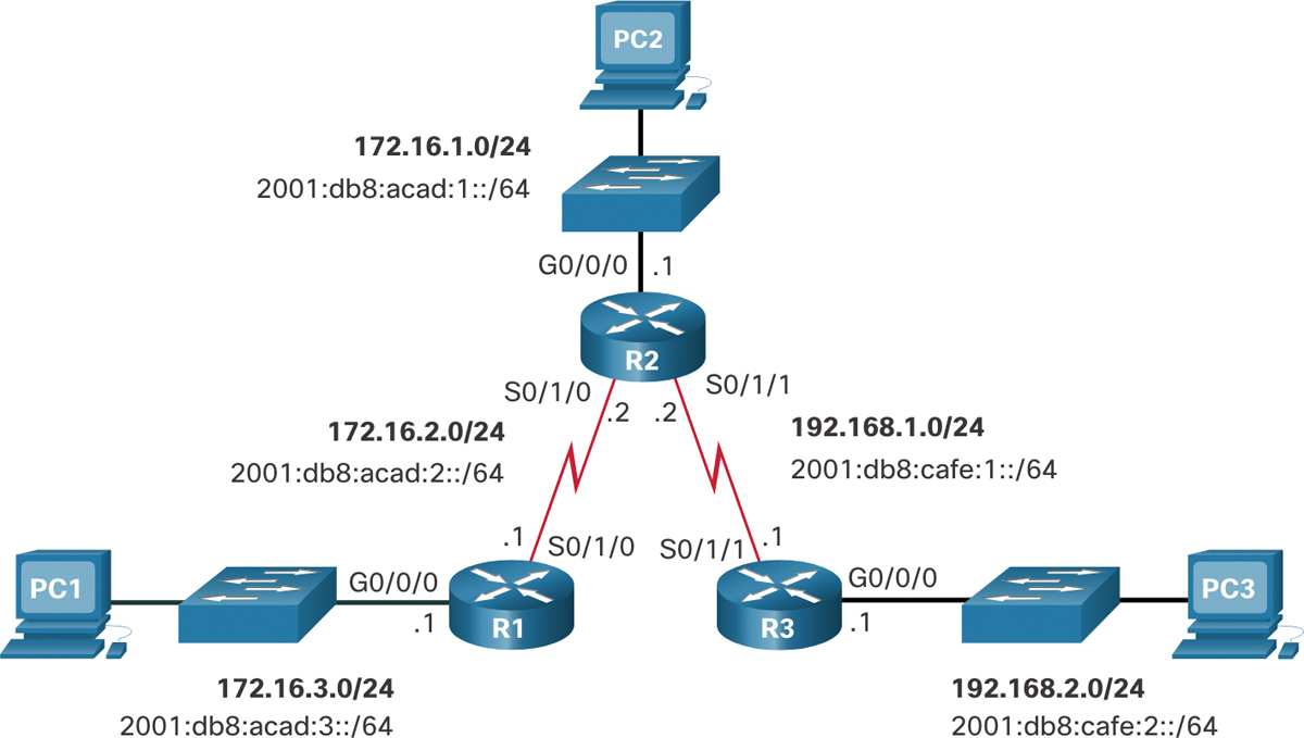
Figure 15-1 Dual-Stack Reference Topology
IPv4 Starting Routing Tables (15.1.6)
Examples 15-1 through 15-3 show the IPv4 routing table of each router. Notice that each router has entries only for directly connected networks and associated local addresses.
Example 15-1 R1 IPv4 Routing Table
R1# show ip route | begin Gateway
Gateway of last resort is not set
      172.16.0.0/16 is variably subnetted, 4 subnets, 2 masks
C        172.16.2.0/24 is directly connected, Serial0/1/0
L        172.16.2.1/32 is directly connected, Serial0/1/0
C        172.16.3.0/24 is directly connected, GigabitEthernet0/0/0
L        172.16.3.1/32 is directly connected, GigabitEthernet0/0/0
R1#
Example 15-2 R2 IPv4 Routing Table
R2# show ip route | begin Gateway
Gateway of last resort is not set
      172.16.0.0/16 is variably subnetted, 4 subnets, 2 masks
C        172.16.1.0/24 is directly connected, GigabitEthernet0/0/0
L        172.16.1.1/32 is directly connected, GigabitEthernet0/0/0
C        172.16.2.0/24 is directly connected, Serial0/1/0
L        172.16.2.2/32 is directly connected, Serial0/1/0
      192.168.1.0/24 is variably subnetted, 2 subnets, 2 masks
C        192.168.1.0/24 is directly connected, Serial0/1/1
L        192.168.1.2/32 is directly connected, Serial0/1/1
R2#
Example 15-3 R3 IPv4 Routing Table
R3# show ip route | begin Gateway
Gateway of last resort is not set
      192.168.1.0/24 is variably subnetted, 2 subnets, 2 masks
C        192.168.1.0/24 is directly connected, Serial0/1/1
L        192.168.1.1/32 is directly connected, Serial0/1/1
      192.168.2.0/24 is variably subnetted, 2 subnets, 2 masks
C        192.168.2.0/24 is directly connected, GigabitEthernet0/0/0
L        192.168.2.1/32 is directly connected, GigabitEthernet0/0/0
R3#
None of the routers have knowledge of any networks beyond the directly connected interfaces. This means each router can only reach directly connected networks, as demonstrated in the ping tests.
In Example 15-4, a ping from R1 to the Serial 0/1/0 interface of R2 should be successful because it is a directly connected network.
R1# ping 172.16.2.2
Type escape sequence to abort.
Sending 5, 100-byte ICMP Echos to 172.16.2.2, timeout is 2 seconds:
!!!!!
However, as shown in Example 15-5, a ping from R1 to the R3 LAN should fail because R1 does not have an entry in its routing table for the R3 LAN network.
Example 15-5 R1 Cannot Ping R3 LAN
R1# ping 192.168.2.1
Type escape sequence to abort.
Sending 5, 100-byte ICMP Echos to 192.168.2.1, timeout is 2 seconds:
.....
Success rate is 0 percent (0/5)
IPv6 Starting Routing Tables (15.1.7)
Examples 15-6 through 15-8 show the IPv6 routing table of each router. Notice that each router has entries only for directly connected networks and associated local addresses.
Example 15-6 R1 IPv6 Routing Table
R1# show ipv6 route | begin C
C   2001:DB8:ACAD:2::/64 [0/0]
     via Serial0/1/0, directly connected
L   2001:DB8:ACAD:2::1/128 [0/0]
     via Serial0/1/0, receive
C   2001:DB8:ACAD:3::/64 [0/0]
     via GigabitEthernet0/0/0, directly connected
L   2001:DB8:ACAD:3::1/128 [0/0]
     via GigabitEthernet0/0/0, receive
L   FF00::/8 [0/0]
     via Null0, receive
R1#
Example 15-7 R2 IPv6 Routing Table
R2# show ipv6 route | begin C
C   2001:DB8:ACAD:1::/64 [0/0]
     via GigabitEthernet0/0/0, directly connected
L   2001:DB8:ACAD:1::1/128 [0/0]
     via GigabitEthernet0/0/0, receive
C   2001:DB8:ACAD:2::/64 [0/0]
     via Serial0/1/0, directly connected
L   2001:DB8:ACAD:2::2/128 [0/0]
     via Serial0/1/0, receive
C   2001:DB8:CAFE:1::/64 [0/0]
     via Serial0/1/1, directly connected
L   2001:DB8:CAFE:1::2/128 [0/0]
     via Serial0/1/1, receive
L   FF00::/8 [0/0]
     via Null0, receive
R2#
Example 15-8 R3 IPv6 Routing Table
R3# show ipv6 route | begin C
C   2001:DB8:CAFE:1::/64 [0/0]
     via Serial0/1/1, directly connected
L   2001:DB8:CAFE:1::1/128 [0/0]
     via Serial0/1/1, receive
C   2001:DB8:CAFE:2::/64 [0/0]
     via GigabitEthernet0/0/0, directly connected
L   2001:DB8:CAFE:2::1/128 [0/0]
     via GigabitEthernet0/0/0, receive
L   FF00::/8 [0/0]
     via Null0, receive
R3#
None of the routers have knowledge of any networks beyond the directly connected interfaces.
As shown Example 15-9, a ping from R1 to the Serial 0/1/0 interface on R2 should be successful.
R1# ping 2001:db8:acad:2::2
Type escape sequence to abort.
Sending 5, 100-byte ICMP Echos to 2001:DB8:ACAD:2::2, timeout is 2 seconds:
!!!!!
Success rate is 100 percent (5/5), round-trip min/avg/max = 2/2/3 ms
R1#
However, a ping to the R3 LAN is unsuccessful, as shown in Example 15-10. This is because R1 does not have an entry in its routing table for that network.
Example 15-10 R1 Cannot Ping R3 LAN
R1# ping 2001:DB8:cafe:2::1
Type escape sequence to abort.
Sending 5, 100-byte ICMP Echos to 2001:DB8:CAFE:2::1, timeout is 2 seconds:
% No valid route for destination
Success rate is 0 percent (0/1)
R1#
Check Your Understanding—Static Routes (15.1.8)
![]()
Refer to the online course to complete this activity.
Configure IP Static Routes (15.2)
Static routes are manually entered; therefore, careful consideration and attention must be given when configuring them.
In this section, you learn how to configure IPv4 and IPv6 static routes to enable remote network connectivity in a small- to medium-sized business network.
IPv4 Next-Hop Static Route (15.2.1)
The commands to configure standard static routes vary slightly between IPv4 and IPv6. This section shows you how to configure standard next-hop, directly connected, and fully specified static routes for both IPv4 and IPv6.
In a next-hop static route, only the next-hop IP address is specified. The exit interface is derived from the next hop. For example, three next-hop IPv4 static routes are configured on R1 using the IP address of the next hop, R2.
The commands to configure R1 with the IPv4 static routes to the three remote networks are shown in Example 15-11.
Example 15-11 IPv4 Next-Hop Static Route Configuration on R1
R1(config)# ip route 172.16.1.0 255.255.255.0 172.16.2.2
R1(config)# ip route 192.168.1.0 255.255.255.0 172.16.2.2
R1(config)# ip route 192.168.2.0 255.255.255.0 172.16.2.2
R1(config)#
The routing table for R1 now has routes to the three remote IPv4 networks, as shown in Example 15-12.
Example 15-12 R1 IPv4 Routing Table
R1# show ip route | begin Gateway
Gateway of last resort is not set
      172.16.0.0/16 is variably subnetted, 5 subnets, 2 masks
S        172.16.1.0/24 [1/0] via 172.16.2.2
C        172.16.2.0/24 is directly connected, Serial0/1/0
L        172.16.2.1/32 is directly connected, Serial0/1/0
C        172.16.3.0/24 is directly connected, GigabitEthernet0/0/0
L        172.16.3.1/32 is directly connected, GigabitEthernet0/0/0
S     192.168.1.0/24 [1/0] via 172.16.2.2
S     192.168.2.0/24 [1/0] via 172.16.2.2
R1#
IPv6 Next-Hop Static Route (15.2.2)
The commands to configure R1 with the IPv6 static routes to the three remote networks are shown in Example 15-13.
Example 15-13 IPv6 Next-Hop Static Route Configuration on R1
R1(config)# ipv6 unicast-routing
R1(config)# ipv6 route 2001:db8:acad:1::/64 2001:db8:acad:2::2
R1(config)# ipv6 route 2001:db8:cafe:1::/64 2001:db8:acad:2::2
R1(config)# ipv6 route 2001:db8:cafe:2::/64 2001:db8:acad:2::2
R1(config)#
The routing table for R1 now has routes to the three remote IPv6 networks, as shown in Example 15-14.
Example 15-14 R1 IPv6 Routing Table
R1# show ipv6 route
IPv6 Routing Table - default - 8 entries
Codes: C - Connected, L - Local, S - Static, U - Per-user Static route
       B - BGP, R - RIP, H - NHRP, I1 - ISIS L1
       I2 - ISIS L2, IA - ISIS interarea, IS - ISIS summary, D - EIGRP
       EX - EIGRP external, ND - ND Default, NDp - ND Prefix, DCE - Destination
       NDr - Redirect, RL - RPL, O - OSPF Intra, OI - OSPF Inter
       OE1 - OSPF ext 1, OE2 - OSPF ext 2, ON1 - OSPF NSSA ext 1
       ON2 - OSPF NSSA ext 2, la - LISP alt, lr - LISP site-registrations
       ld - LISP dyn-eid, lA - LISP away, le - LISP extranet-policy
       a - Application
S   2001:DB8:ACAD:1::/64 [1/0]
     via 2001:DB8:ACAD:2::2
C   2001:DB8:ACAD:2::/64 [0/0]
     via Serial0/1/0, directly connected
L   2001:DB8:ACAD:2::1/128 [0/0]
     via Serial0/1/0, receive
C   2001:DB8:ACAD:3::/64 [0/0]
     via GigabitEthernet0/0/0, directly connected
L   2001:DB8:ACAD:3::1/128 [0/0]
     via GigabitEthernet0/0/0, receive
S   2001:DB8:CAFE:1::/64 [1/0]
     via 2001:DB8:ACAD:2::2
S   2001:DB8:CAFE:2::/64 [1/0]
     via 2001:DB8:ACAD:2::2
L   FF00::/8 [0/0]
     via Null0, receive
R1#
IPv4 Directly Connected Static Route (15.2.3)
When configuring a static route, another option is to use the exit interface to specify the next-hop address. Three directly connected IPv4 static routes are configured on R1 using the exit interface, as shown in Example 15-15.
Example 15-15 IPv4 Directly Connected Static Route Configuration on R1
R1(config)# ip route 172.16.1.0 255.255.255.0 s0/1/0
R1(config)# ip route 192.168.1.0 255.255.255.0 s0/1/0
R1(config)# ip route 192.168.2.0 255.255.255.0 s0/1/0
In Example 15-16, the IPv4 routing table for R1 shows that when a packet is destined for the 192.168.2.0/24 network, R1 looks for a match in the routing table and finds that it can forward the packet out of its Serial 0/1/0 interface.
Note
Using a next-hop address is generally recommended. Directly connected static routes should be used only with point-to-point (P2P) serial interfaces, as in this example.
Example 15-16 R1 IPv4 Routing Table
R1# show ip route | begin Gateway
Gateway of last resort is not set
      172.16.0.0/16 is variably subnetted, 5 subnets, 2 masks
S        172.16.1.0/24 is directly connected, Serial0/1/0
C        172.16.2.0/24 is directly connected, Serial0/1/0
L        172.16.2.1/32 is directly connected, Serial0/1/0
C        172.16.3.0/24 is directly connected, GigabitEthernet0/0/0
L        172.16.3.1/32 is directly connected, GigabitEthernet0/0/0
S     192.168.1.0/24 is directly connected, Serial0/1/0
S     192.168.2.0/24 is directly connected, Serial0/1/0
R1#
IPv6 Directly Connected Static Route (15.2.4)
In Example 15-17, three directly connected IPv6 static routes are configured on R1 using the exit interface.
Example 15-17 IPv6 Directly Connected Static Route Configuration on R1
R1(config)# ipv6 route 2001:db8:acad:1::/64 s0/1/0
R1(config)# ipv6 route 2001:db8:cafe:1::/64 s0/1/0
R1(config)# ipv6 route 2001:db8:cafe:2::/64 s0/1/0
R1(config)#
The IPv6 routing table for R1 in Example 15-18 shows that when a packet is destined for the 2001:db8:cafe:2::/64 network, R1 looks for a match in the routing table and finds that it can forward the packet out of its Serial 0/1/0 interface.
Note
Using a next-hop address is generally recommended. Directly connected static routes should be used only with point-to-point serial interfaces, as in this example.
Example 15-18 R1 IPv6 Routing Table
R1# show ipv6 route
IPv6 Routing Table - default - 8 entries
Codes: C - Connected, L - Local, S - Static, U - Per-user Static route
       B - BGP, R - RIP, H - NHRP, I1 - ISIS L1
       I2 - ISIS L2, IA - ISIS interarea, IS - ISIS summary, D - EIGRP
       EX - EIGRP external, ND - ND Default, NDp - ND Prefix, DCE - Destination
       NDr - Redirect, RL - RPL, O - OSPF Intra, OI - OSPF Inter
       OE1 - OSPF ext 1, OE2 - OSPF ext 2, ON1 - OSPF NSSA ext 1
       ON2 - OSPF NSSA ext 2, la - LISP alt, lr - LISP site-registrations
       ld - LISP dyn-eid, lA - LISP away, le - LISP extranet-policy
       a - Application
S   2001:DB8:ACAD:1::/64 [1/0]
     via Serial0/1/0, directly connected
C   2001:DB8:ACAD:2::/64 [0/0]
     via Serial0/1/0, directly connected
L   2001:DB8:ACAD:2::1/128 [0/0]
     via Serial0/1/0, receive
C   2001:DB8:ACAD:3::/64 [0/0]
     via GigabitEthernet0/0/0, directly connected
L   2001:DB8:ACAD:3::1/128 [0/0]
     via GigabitEthernet0/0/0, receive
S   2001:DB8:CAFE:1::/64 [1/0]
     via Serial0/1/0, directly connected
S   2001:DB8:CAFE:2::/64 [1/0]
     via Serial0/1/0, directly connected
L   FF00::/8 [0/0]
     via Null0, receiveIPv6 Routing Table - default - 8 entries
R1#
IPv4 Fully Specified Static Route (15.2.5)
In a fully specified static route, both the exit interface and the next-hop IP address are specified. This form of static route is used when the exit interface is a multiaccess interface and it is necessary to explicitly identify the next hop. The next hop must be directly connected to the specified exit interface. Using an exit interface is optional; however, it is necessary to use a next-hop address.
Suppose that the network link between R1 and R2 is an Ethernet link and that the GigabitEthernet 0/0/1 interface of R1 is connected to that network, as shown in Figure 15-2.

Figure 15-2 Dual-Stack Reference Topology with Ethernet Link Between R1 and R2
The difference between an Ethernet multiaccess network and a point-to-point serial network is that a point-to-point serial network has only one other device on that network, the router at the other end of the link. With Ethernet networks, there may be many different devices sharing the same multiaccess network, including hosts and even multiple routers.
It is recommended that when the exit interface is an Ethernet network, the static route includes a next-hop address. You can also use a fully specified static route that includes both the exit interface and the next-hop address, as shown for R1 fully specified static routes in Example 15-19.
Example 15-19 IPv4 Fully Specified Static Route Configuration on R1
R1(config)# ip route 172.16.1.0 255.255.255.0 GigabitEthernet 0/0/1 172.16.2.2
R1(config)# ip route 192.168.1.0 255.255.255.0 GigabitEthernet 0/0/1 172.16.2.2
R1(config)# ip route 192.168.2.0 255.255.255.0 GigabitEthernet 0/0/1 172.16.2.2
R1(config)#
When forwarding packets to R2, the exit interface is GigabitEthernet 0/0/1 and the next-hop IPv4 address is 172.16.2.2, as shown in the show ip route output from R1 in Example 15-20.
Example 15-20 R1 IPv4 Routing Table
R1# show ip route | begin Gateway
Gateway of last resort is not set
      172.16.0.0/16 is variably subnetted, 5 subnets, 2 masks
S        172.16.1.0/24 [1/0] via 172.16.2.2, GigabitEthernet0/0/1
C        172.16.2.0/24 is directly connected, GigabitEthernet0/0/1
L        172.16.2.1/32 is directly connected, GigabitEthernet0/0/1
C        172.16.3.0/24 is directly connected, GigabitEthernet0/0/0
L        172.16.3.1/32 is directly connected, GigabitEthernet0/0/0
S     192.168.1.0/24 [1/0] via 172.16.2.2, GigabitEthernet0/0/1
S     192.168.2.0/24 [1/0] via 172.16.2.2, GigabitEthernet0/0/1
R1#
IPv6 Fully Specified Static Route (15.2.6)
In a fully specified IPv6 static route, both the exit interface and the next-hop IPv6 address are specified. There is a situation in IPv6 when a fully specified static route must be used. If the IPv6 static route uses an IPv6 link-local address as the next-hop address, use a fully specified static route. Figure 15-3 shows a topology of just R1 and R2 to demonstrate a fully specified IPv6 static route configuration using an IPv6 link-local address as the next-hop address.
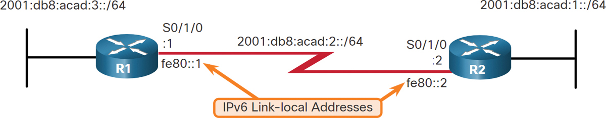
Figure 15-3 IPv6 Topology for Fully Specified Static Route Configuration
In Example 15-21, a fully specified static route is configured using the link-local address of R2 as the next-hop address. Notice that Internetwork Operating System (IOS) requires that an exit interface be specified.
Example 15-21 IPv6 Fully Specified Static Route on R1
R1(config)# ipv6 route 2001:db8:acad:1::/64 fe80::2
%Interface has to be specified for a link-local nexthop
R1(config)# ipv6 route 2001:db8:acad:1::/64 s0/1/0 fe80::2
R1(config)#
The reason a fully specified static route must be used is because IPv6 link-local addresses are not contained in the IPv6 routing table. Link-local addresses are unique only on a given link or network. The next-hop link-local address may be a valid address on multiple networks connected to the router. Therefore, it is necessary that the exit interface be included.
Example 15-22 shows the IPv6 routing table entry for this route. Notice that both the next-hop link-local address and the exit interface are included.
Example 15-22 R1 IPv6 Routing Table
R1# show ipv6 route static | begin 2001:db8:acad:1::/64
S   2001:DB8:ACAD:1::/64 [1/0]
    via FE80::2, Seria0/1/0
R1#
Verify a Static Route (15.2.7)
Along with show ip route, show ipv6 route, ping, and traceroute, other useful commands to verify static routes include the following:
show ip route static
show ip route network
show running-config | section ip route
Replace ip with ipv6 for the IPv6 versions of the command. Figure 15-4 repeats the dual-stack reference topology that is used for the following command examples.

Figure 15-4 Dual-Stack Reference Topology
Display Only IPv4 Static Routes
The output in Example 15-23 shows only the IPv4 static routes in the routing table. Also note where the filter begins the output, excluding all the codes.
Example 15-23 Display Only IPv4 Static Routes
R1# show ip route static | begin Gateway
Gateway of last resort is not set
      172.16.0.0/16 is variably subnetted, 5 subnets, 2 masks
S        172.16.1.0/24 [1/0] via 172.16.2.2
S     192.168.1.0/24 [1/0] via 172.16.2.2
S     192.168.2.0/24 [1/0] via 172.16.2.2
R1#
Display a Specific IPv4 Network
Example 15-24 shows only the output for only the specified network in the routing table.
Example 15-24 Display a Specific IPv4 Network
R1# show ip route 192.168.2.1
Routing entry for 192.168.2.0/24
  Known via "static", distance 1, metric 0
  Routing Descriptor Blocks:
  * 172.16.2.2
      Route metric is 0, traffic share count is 1
R1#
Display the IPv4 Static Route Configuration
The command in Example 15-25 filters the running configuration for only IPv4 static routes.
Example 15-25 Display the IPv4 Static Route Configuration
R1# show running-config | section ip route
ip route 172.16.1.0 255.255.255.0 172.16.2.2
ip route 192.168.1.0 255.255.255.0 172.16.2.2
ip route 192.168.2.0 255.255.255.0 172.16.2.2
R1#
Display Only IPv6 Static Routes
The output in Example 15-26 shows only the IPv6 static routes in the routing table.
Example 15-26 Display Only IPv6 Static Routes
R1# show ipv6 route static
IPv6 Routing Table - default - 8 entries
Codes:  C - Connected, L - Local, S - Static, U - Per-user Static route
        B - BGP, R - RIP, H - NHRP, I1 - ISIS L1
        I2 - ISIS L2, IA - ISIS interarea, IS - ISIS summary, D - EIGRP
        EX - EIGRP external, ND - ND Default, NDp - ND Prefix, DCE - Destination
        NDr - Redirect, RL - RPL, O - OSPF Intra, OI - OSPF Inter
        OE1 - OSPF ext 1, OE2 - OSPF ext 2, ON1 - OSPF NSSA ext 1
        ON2 - OSPF NSSA ext 2, la - LISP alt, lr - LISP site-registrations
        ld - LISP dyn-eid, lA - LISP away, le - LISP extranet-policy
        a - Application
S   2001:DB8:ACAD:1::/64 [1/0]
     via 2001:DB8:ACAD:2::2
S   2001:DB8:CAFE:1::/64 [1/0]
     via 2001:DB8:ACAD:2::2
S   2001:DB8:CAFE:2::/64 [1/0]
     via 2001:DB8:ACAD:2::2
R1#
Display a Specific IPv6 Network
The command in Example 15-27 shows output for only the specified network in the routing table.
Example 15-27 Display a Specific IPv6 Network
R1# show ipv6 route 2001:db8:cafe:2::
Routing entry for 2001:DB8:CAFE:2::/64
  Known via "static", distance 1, metric 0
  Route count is 1/1, share count 0
  Routing paths:
    2001:DB8:ACAD:2::2
      Last updated 00:23:55 ago

R1#
Display the IPv6 Static Route Configuration
The command in Example 15-28 filters the running configuration for only IPv6 static routes.
Example 15-28 Display the IPv6 Static Route Configuration
R1# show running-config | section ipv6 route
ipv6 route 2001:DB8:ACAD:1::/64 2001:DB8:ACAD:2::2
ipv6 route 2001:DB8:CAFE:1::/64 2001:DB8:ACAD:2::2
ipv6 route 2001:DB8:CAFE:2::/64 2001:DB8:ACAD:2::2
R1#
Syntax Checker—Configure Static Routes (15.2.8)
![]()
Refer to the online course to complete this activity.
Configure IP Default Static Routes (15.3)
In this section, you learn how to configure an IPv4 and IPv6 default static route.
Default Static Route (15.3.1)
This section shows you how to configure a default route for IPv4 and IPv6. It also explains the situations in which a default route is a good choice. A default route is a static route that matches all packets. Instead of routers storing routes for all the networks in the Internet, they can store a single default route to represent any network that is not in the routing table.
Routers commonly use default routes that are either configured locally or learned from another router, using a dynamic routing protocol. A default route does not require any far-left bits to match between the default route and the destination IP address. A default route is used when no other routes in the routing table match the destination IP address of the packet. In other words, if a more specific match does not exist, the default route is used as the Gateway of Last Resort.
Default static routes are commonly used when connecting an edge router to a service provider network, or a stub router (a router with only one upstream neighbor router).
Figure 15-5 shows a typical default static route scenario.
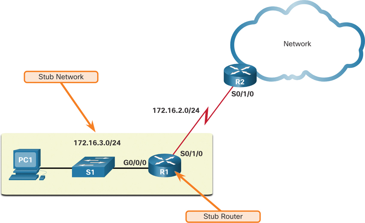
Figure 15-5 Default Static Route Stub Network Topology
IPv4 Default Static Route
The command syntax for an IPv4 default static route is similar to any other IPv4 static route, except that the network address is 0.0.0.0 and the subnet mask is 0.0.0.0. The 0.0.0.0 0.0.0.0 in the route will match any network address.
Note
An IPv4 default static route is commonly referred to as a quad-zero route.
The basic command syntax for an IPv4 default static route is as follows:
Router(config)# ip route 0.0.0.0 0.0.0.0 {ip-address | exit-intf}
IPv6 Default Static Route
The command syntax for an IPv6 default static route is similar to any other IPv6 static route, except that the ipv6-prefix/prefix-length is ::/0, which matches all routes.
The basic command syntax for an IPv6 default static route is as follows:
Router(config)# ipv6 route ::/0 {ipv6-address | exit-intf}
Configure a Default Static Route (15.3.2)
In Figure 15-6, R1 could be configured with three static routes, one to reach each of the remote networks in the example topology. However, R1 is a stub router because it is only connected to R2. Therefore, it would be more efficient to configure a single default static route.
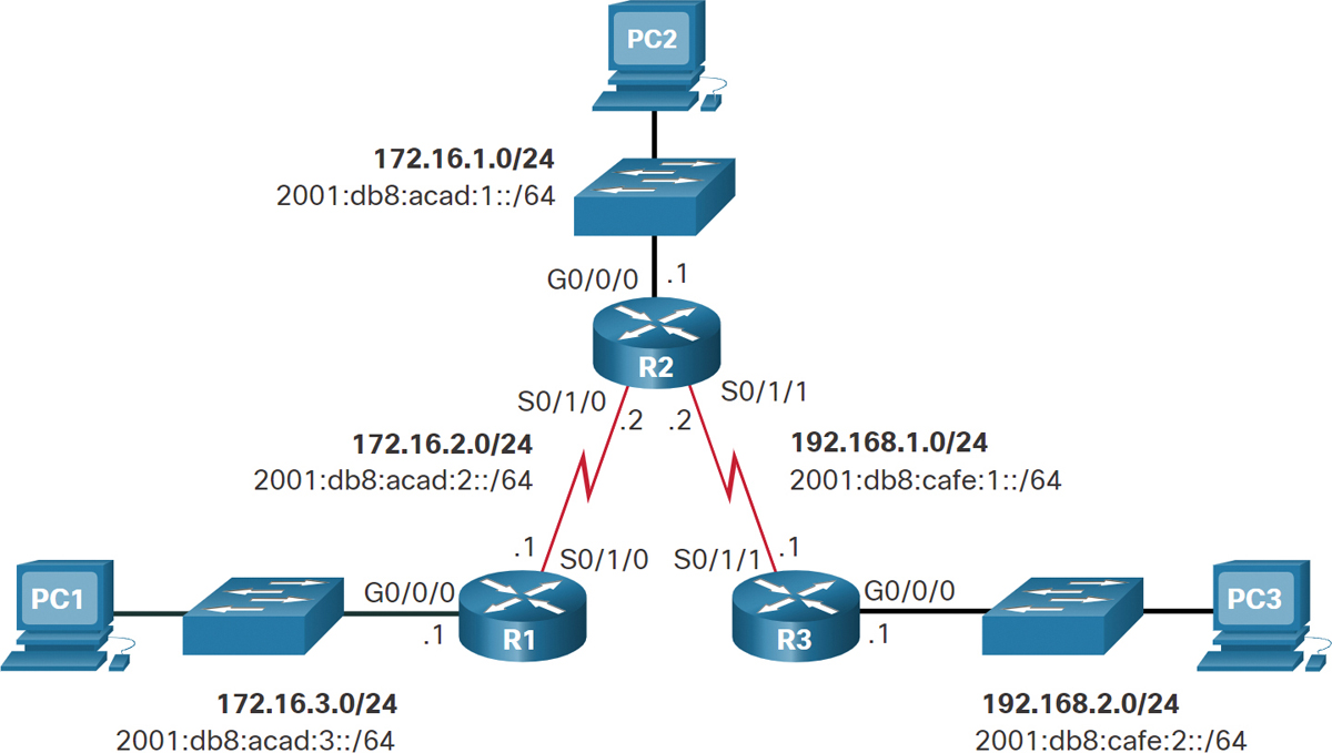
Figure 15-6 Dual Stack Reference Topology
Example 15-29 shows an IPv4 default static route configured on R1. With the configuration shown in the example, any packets not matching more specific route entries are forwarded to R2 at 172.16.2.2.
Example 15-29 IPv4 Default Static Route on R1
R1(config)# ip route 0.0.0.0 0.0.0.0 172.16.2.2
An IPv6 default static route is configured in similar fashion, as shown in Example 15-30. With this configuration any packets not matching more specific IPv6 route entries are forwarded to R2 at 2001:db8:acad:2::2.
Example 15-30 IPv6 Default Static Route on R1
R1(config)# ipv6 route ::/0 2001:db8:acad:2::2
Verify a Default Static Route (15.3.3)
In Example 15-31, the show ip route static command output from R1 displays the contents of the static routes in the routing table. Note the asterisk (*) next to the route with code S. As displayed in the codes table in the show ip route output, the asterisk indicates that this static route is a candidate default route, which is why it is selected as the Gateway of Last Resort.
Example 15-31 R1 IPv4 Default Route in the Routing Table
R1# show ip route static
Codes: L - local, C - connected, S - static, R - RIP, M - mobile, B - BGP
D - EIGRP, EX - EIGRP external, O - OSPF, IA - OSPF inter area
N1 - OSPF NSSA external type 1, N2 - OSPF NSSA external type 2
E1 - OSPF external type 1, E2 - OSPF external type 2
i - IS-IS, su - IS-IS summary, L1 - IS-IS level-1, L2 - IS-IS level-2
ia - IS-IS inter area, * - candidate default, U - per-user static route
o - ODR, P - periodic downloaded static route, H - NHRP, l - LISP
+ - replicated route, % - next hop override

Gateway of last resort is 172.16.2.2 to network 0.0.0.0

S* 0.0.0.0/0 [1/0] via 172.16.2.2

R1#
Example 15-32 shows the show ipv6 route static command output to display the contents of the routing table.
Example 15-32 R1 IPv6 Default Route in the Routing Table
R1# show ipv6 route static
IPv6 Routing Table - default - 8 entries
Codes:  C - Connected, L - Local, S - Static, U - Per-user Static route
        B - BGP, R - RIP, H - NHRP, I1 - ISIS L1
        I2 - ISIS L2, IA - ISIS interarea, IS - ISIS summary, D - EIGRP
        EX - EIGRP external, ND - ND Default, NDp - ND Prefix, DCE - Destination
        NDr - Redirect, RL - RPL, O - OSPF Intra, OI - OSPF Inter
        OE1 - OSPF ext 1, OE2 - OSPF ext 2, ON1 - OSPF NSSA ext 1
        ON2 - OSPF NSSA ext 2, la - LISP alt, lr - LISP site-registrations
        ld - LISP dyn-eid, lA - LISP away, le - LISP extranet-policy
        a - Application
S   ::/0 [1/0]
     via 2001:DB8:ACAD:2::2
R1#
Notice that the static default route configuration uses the /0 mask for IPv4 default routes and the ::/0 prefix for IPv6 default routes. Remember that the IPv4 subnet mask and IPv6 prefix-length in a routing table determine how many bits must match between the destination IP address of the packet and the route in the routing table. A /0 mask or ::/0 prefix indicates that none of the bits are required to match. As long as a more specific match does not exist, the default static route matches all packets.
Syntax Checker—Configure Default Static Routes (15.3.4)
![]()
Refer to the online course to complete this activity.
Configure Floating Static Routes (15.4)
In this section, you learn how to configure IPv4 and IPv6 floating static routes to provide a backup connection.
Floating Static Routes (15.4.1)
As with the other sections in this module, you learn how to configure IPv4 and IPv6 floating static routes and when to use them.
Another type of static route is a floating static route. Floating static routes are static routes that are used to provide a backup path to a primary static or dynamic route, in the event of a link failure. The floating static route is used only when the primary route is not available.
To accomplish this, the floating static route is configured with a higher administrative distance than the primary route. The administrative distance represents the trustworthiness of a route. If multiple paths to the destination exist, the router will choose the path with the lowest administrative distance.
For example, assume that an administrator wants to create a floating static route as a backup to an EIGRP-learned route. The floating static route must be configured with a higher administrative distance than Enhanced Interior Gateway Routing Protocol (EIGRP). EIGRP has an administrative distance of 90. If the floating static route is configured with an administrative distance of 95, the dynamic route learned through EIGRP is preferred to the floating static route. If the EIGRP-learned route is lost, the floating static route is used in its place.
In Figure 15-7, the branch router typically forwards all traffic to the HQ router over the private WAN link. In this example, the routers exchange route information using EIGRP. A floating static route, with an administrative distance of 91 or higher, could be configured to serve as a backup route. If the private WAN link fails and the EIGRP route disappears from the routing table, the router selects the floating static route as the best path to reach the HQ LAN.
A route learned through dynamic routing is preferred.
If a dynamic route is lost, the floating static route will be used.

Figure 15-7 Floating Static Route Topology
By default, static routes have an administrative distance of 1, making them preferable to routes learned from dynamic routing protocols. For example, the administrative distances of some common interior gateway dynamic routing protocols are as follows:
EIGRP = 90
OSPF = 110
IS-IS = 115
The administrative distance of a static route can be increased to make the route less desirable than that of another static route or a route learned through a dynamic routing protocol. In this way, the static route “floats” and is not used when the route with the better administrative distance is active. However, if the preferred route is lost, the floating static route can take over, and traffic can be sent through this alternate route.
Configure IPv4 and IPv6 Floating Static Routes (15.4.2)
IP floating static routes are configured by using the distance argument to specify an administrative distance. If no administrative distance is configured, the default value (1) is used.
Refer to the topology in Figure 15-8. In this scenario, the preferred default route from R1 is to R2. The connection to R3 should be used for backup only.

Figure 15-8 Full Mesh Dual-Stack Reference Topology
In Example 15-33, R1 is configured with IPv4 and IPv6 default static routes pointing to R2. Because no administrative distance is configured, the default value (1) is used for these static routes. R1 is also configured with IPv4 and IPv6 floating static default routes pointing to R3 with an administrative distance of 5. This value is greater than the default value of 1; therefore, this route floats and is not present in the routing table unless the preferred route fails.
Example 15-33 IPv4 and IPv6 Floating Static Route Configuration on R1
R1(config)# ip route 0.0.0.0 0.0.0.0 172.16.2.2
R1(config)# ip route 0.0.0.0 0.0.0.0 10.10.10.2 5
R1(config)# ipv6 route ::/0 2001:db8:acad:2::2
R1(config)# ipv6 route ::/0 2001:db8:feed:10::2 5
R1(config)#
The show ip route static and show ipv6 route static output in Example 15-34 verifies that the default routes to R2 are installed in the routing table. Note that the IPv4 floating static route to R3 is not present in the routing table.
Example 15-34 R1 IPv4 and IPv6 Routing Tables
R1# show ip route static | begin Gateway
Gateway of last resort is 172.16.2.2 to network 0.0.0.0

S*   0.0.0.0/0 [1/0] via 172.16.2.2
R1#
R1# show ipv6 route static | begin S :
S   ::/0 [1/0]
     via 2001:DB8:ACAD:2::2
R1#
Use the show run command to verify that floating static routes are in the configuration. The command output in Example 15-35 verifies that both IPv6 static default routes are in the running configuration.
Example 15-35 Verifying an IPv6 Floating Static Route Is in the Configuration
R1# show run | include ipv6 route
ipv6 route ::/0 2001:db8:feed:10::2 5
ipv6 route ::/0 2001:db8:acad:2::2
R1#
Test the Floating Static Route (15.4.3)
What would happen if R2 failed? To simulate this failure, both serial interfaces of R2 are shut down, as shown in Example 15-36.
Example 15-36 Testing a Floating Static Route
R2(config)# interface s0/1/0
R2(config-if)# shut
*Sep 18 23:36:27.000: %LINK-5-CHANGED: Interface Serial0/1/0, changed state to
  administratively down
*Sep 18 23:36:28.000: %LINEPROTO-5-UPDOWN: Line protocol on Interface Serial0/1/0,
  changed state to down
R2(config-if)# interface s0/1/1
R2(config-if)# shut
*Sep 18 23:36:41.598: %LINK-5-CHANGED: Interface Serial0/1/1, changed state to
  administratively down
*Sep 18 23:36:42.598: %LINEPROTO-5-UPDOWN: Line protocol on Interface Serial0/1/1,
  changed state to down
R1(config-if)# end
R1#
Notice that R1 automatically generates messages indicating that the serial interface to R2 is down, as shown in Example 15-37.
Example 15-37 Log Messages on R1
R1#
*Sep 18 23:35:48.810: %LINK-3-UPDOWN: Interface Serial0/1/0, changed state to down
R1#
*Sep 18 23:35:49.811: %LINEPROTO-5-UPDOWN: Line protocol on Interface Serial0/1/0,
  changed state to down
R1#
A look at the IP routing tables of R1 verifies that the floating static default routes are now installed as the default routes and are pointing to R3 as the next-hop router, as shown in Example 15-38.
Example 15-38 Verifying Floating Static Routes are Now Installed on R1
R1# show ip route static | begin Gateway
Gateway of last resort is 10.10.10.2 to network 0.0.0.0
S*    0.0.0.0/0 [5/0] via 10.10.10.2
R1#
R1# show ipv6 route static | begin ::
S   ::/0 [5/0]
     via 2001:DB8:FEED:10::2
R1#
Syntax Checker—Configure Floating Static Route (15.4.4)
![]()
Refer to the online course to complete this activity.
Configure Static Host Routes (15.5)
In this section, you will learn how to configure IPv4 and IPv6 static host routes that direct traffic to a specific host.
Host Routes (15.5.1)
This section shows you how to configure an IPv4 and IPv6 static host route and when to use them.
A host route is an IPv4 address with a 32-bit mask, or an IPv6 address with a 128-bit mask. The following shows the three ways a host route can be added to the routing table:
Automatically installed when an IP address is configured on the router (as shown in the figures)
Configured as a static host route
Host route automatically obtained through other methods (discussed in later courses)
Automatically Installed Host Routes (15.5.2)
Cisco IOS automatically installs a host route, also known as a local host route, when an interface address is configured on the router. A host route allows for a more efficient process for packets that are directed to the router itself, rather than for packet forwarding. This is in addition to the connected route, designated with a C in the routing table for the network address of the interface.
When an active interface on a router is configured with an IP address, a local host route is automatically added to the routing table. The local routes are marked with L in the output of the routing table.
For example, refer to the topology in Figure 15-9.
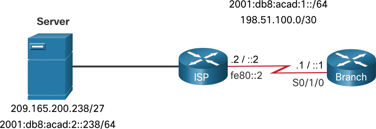
Figure 15-9 Host Route Reference Topology
The IP addresses assigned to the Branch Serial 0/1/0 interface are 198.51.100.1/30 and 2001:db8:acad:1::1/64. The local routes for the interface are installed by the IOS in the IPv4 and IPv6 routing tables, as shown in Example 15-39.
Example 15-39 Local IPv4 and IPv6 Routes
Branch# show ip route | begin Gateway
Gateway of last resort is not set
      198.51.100.0/24 is variably subnetted, 2 subnets, 2 masks
C        198.51.100.0/30 is directly connected, Serial0/1/0
L        198.51.100.1/32 is directly connected, Serial0/1/0
Branch# show ipv6 route | begin ::
C   2001:DB8:ACAD:1::/64 [0/0]
     via Serial0/1/0, directly connected
L   2001:DB8:ACAD:1::1/128 [0/0]
     via Serial0/1/0, receive
L   FF00::/8 [0/0]
     via Null0, receive
Branch#
Static Host Routes (15.5.3)
A host route can be a manually configured static route to direct traffic to a specific destination device, such as the server shown in Figure 15-9. The static route uses a destination IP address and a 255.255.255.255 (/32) mask for IPv4 host routes and a /128 prefix length for IPv6 host routes.
Configure Static Host Routes (15.5.4)
Example 15-40 shows the IPv4 and IPv6 static host route configuration on the Branch router to access the server.
Example 15-40 IPv4 and IPv6 Static Host Route Configuration
Branch(config)# ip route 209.165.200.238 255.255.255.255 198.51.100.2
Branch(config)# ipv6 route 2001:db8:acad:2::238/128 2001:db8:acad:1::2
Branch(config)# exit
Branch#
Verify Static Host Routes (15.5.5)
A review of both the IPv4 and IPv6 route tables verifies that the routes are active, as shown in Example 15-41.
Example 15-41 Verifying the IPv4 and IPv6 Static Host Routes
Branch# show ip route | begin Gateway
Gateway of last resort is not set
      198.51.100.0/24 is variably subnetted, 2 subnets, 2 masks
C        198.51.100.0/30 is directly connected, Serial0/1/0
L        198.51.100.1/32 is directly connected, Serial0/1/0
      209.165.200.0/32 is subnetted, 1 subnets
S        209.165.200.238 [1/0] via 198.51.100.2
Branch#
Branch# show ipv6 route
(Output omitted)
C   2001:DB8:ACAD:1::/64 [0/0]
     via Serial0/1/0, directly connected
L   2001:DB8:ACAD:1::1/128 [0/0]
     via Serial0/1/0, receive
S   2001:DB8:ACAD:2::238/128 [1/0]
     via 2001:DB8:ACAD:1::2
Branch#
Configure IPv6 Static Host Route with Link-Local Next-Hop (15.5.6)
For IPv6 static routes, the next-hop address can be the link-local address of the adjacent router. However, you must specify an interface type and an interface number when using a link-local address as the next hop, as shown in Example 15-42. First, the original IPv6 static host route is removed, then a fully specified route is configured with the IPv6 address of the server and the IPv6 link-local address of the ISP router.
Example 15-42 Configuring and Verifying an IPv6 Static Host Route with Link-Local as the Next-Hop
Branch(config)# no ipv6 route 2001:db8:acad:2::238/128 2001:db8:acad:1::2
Branch(config)# ipv6 route 2001:db8:acad:2::238/128 serial 0/1/0 fe80::2
Branch#
Branch# show ipv6 route | begin ::
C   2001:DB8:ACAD:1::/64 [0/0]
     via Serial0/1/0, directly connected
L   2001:DB8:ACAD:1::1/128 [0/0]
     via Serial0/1/0, receive
S   2001:DB8:ACAD:2::238/128 [1/0]
     via FE80::2, Serial0/1/0
Branch#
Syntax Checker—Configure Static Host Routes (15.5.7)
![]()
Refer to the online course to complete this activity.
Summary (15.6)
The following is a summary of each section in the module:
Static Routes
Static routes can be configured for IPv4 and IPv6. Both protocols support the following types of static routes: standard static route, default static route, floating static route, and summary static route. Static routes are configured using the ip route and ipv6 route global configuration commands. When configuring a static route, the next hop can be identified by an IP address, exit interface, or both. How the destination is specified creates one of the three following types of static route: next-hop, directly connected, and fully specified. IPv4 static routes are configured using the following global configuration command: ip route network-address subnet-mask { ip-address | exit-intf [ip-address] } [distance]. IPv6 static routes are configured using the following global configuration command: ipv6 route ipv6-prefix/prefix-length { ipv6-address | exit-intf [ipv6-address] } [distance]. The command to display an IPv4 routing table is show ip route and the command to display an IPv6 routing table is show ipv6 route.
Configure IP Static Routes
In a next-hop static route, only the next-hop IP address is specified. The exit interface is derived from the next hop. When configuring a static route, another option is to use the exit interface to specify the next-hop address. Directly connected static routes should be used only with point-to-point serial interfaces. In a fully specified static route, both the exit interface and the next-hop IP address are specified. This form of static route is used when the exit interface is a multiaccess interface and it is necessary to explicitly identify the next hop. The next hop must be directly connected to the specified exit interface. In a fully specified IPv6 static route, both the exit interface and the next-hop IPv6 address are specified. Along with show ip route, show ipv6 route, ping, and traceroute, other useful commands to verify static routes include show ip route static, show ip route network, and show running-config | section ip route. Replace ip with ipv6 for the IPv6 versions of the command.
Configure IP Default Static Routes
A default route is a static route that matches all packets. A default route does not require any far-left bits to match between the default route and the destination IP address. Default static routes are commonly used when connecting an edge router to a service provider network, and a stub router. The command syntax for an IPv4 default static route is similar to any other IPv4 static route, except that the network address is 0.0.0.0 and the subnet mask is 0.0.0.0. The 0.0.0.0 0.0.0.0 in the route will match any network address. The command syntax for an IPv6 default static route is similar to any other IPv6 static route, except that the ipv6-prefix/prefix-length is ::/0, which matches all routes. To verify an IPv4 default static route, use the show ip route static command. For IPV6 use the show ipv6 route static command.
Configure Floating Static Routes
Floating static routes are static routes that are used to provide a backup path to a primary static or dynamic route in the event of a link failure. The floating static route is configured with a higher administrative distance than the primary route. By default, static routes have an administrative distance of 1, making them preferable to routes learned from dynamic routing protocols. The administrative distances of some common interior gateway dynamic routing protocols are EIGRP = 90, OSPF = 110, and IS-IS = 115. IP floating static routes are configured by using the distance argument to specify an administrative distance. If no administrative distance is configured, the default value (1) is used. The show ip route and show ipv6 route output verifies that the default routes to a router are installed in the routing table.
Configure Static Host Routes
A host route is an IPv4 address with a 32-bit mask or an IPv6 address with a 128-bit mask. There are three ways a host route can be added to the routing table: automatically installed when an IP address is configured on the router, configured as a static host route, or automatically obtained through other methods not covered in this module. Cisco IOS automatically installs a host route, also known as a local host route, when an interface address is configured on the router. A host route can be a manually configured static route to direct traffic to a specific destination device. For IPv6 static routes, the next-hop address can be the link-local address of the adjacent router; however, you must specify an interface type and an interface number when using a link-local address as the next hop. To do this, the original IPv6 static host route is removed, then a fully specified route is configured with the IPv6 address of the server and the IPv6 link-local address of the ISP router.
Packet Tracer—Configure IPv4 and IPv6 Static and Default Routes (15.6.1)
![]()
In this Packet Tracer summary activity, you will configure static, default, and floating static routes for both the IPv4 and IPv6 protocols.
Lab—Configure IPv4 and IPv6 Static and Default Routes (15.6.2)
![]()
In this lab, you complete the following objectives:
Part 1: Build the Network and Configure Basic Device Settings
Part 2: Configure and Verify IPv4 and IPv6 Addressing on R1 and R2
Part 3: Configure and Verify Static and Default Routing for IPv4 on R1 and R2
Part 4: Configure and Verify Static and Default Routing for IPv6 on R1 and R2
Practice
The following activities provide practice with the topics introduced in this chapter. The Labs are available in the companion Switching, Routing, and Wireless Essentials Labs and Study Guide (CCNAv7) (ISBN 9780136634386). The Packet Tracer Activity instructions are also in the Labs & Study Guide. The PKA files are found in the online course.
Lab
![]()
Lab 15.6.2: Configure IPv4 and IPv6 Static and Default Routes
Packet Tracer Activity
![]()
Packet Tracer 15.6.1: Configure IPv4 and IPv6 Static and Default Routes
Check Your Understanding Questions
Complete all the review questions listed here to test your understanding of the sections and concepts in this chapter. The appendix “Answers to the ‘Check Your Understanding’ Questions” lists the answers.
1. Assume the administrator has entered the ip route 192.168.10.0 255.255.255.0 10.10.10.2 5 command. How would an administrator test this configuration?
Delete the default gateway route on the router.
Manually shut down the router interface used as a primary route.
Ping any valid address on the 192.168.10.0/24 network.
Ping from the 192.168.10.0 network to the 10.10.10.2 address.
2. What route has the highest administrative distance?
A directly connected network
A route received through the EIGRP routing protocol
A route received through the OSPF routing protocol
A static route
3. Which route would be used to forward a packet with a source IP address of 10.10.10.1 and a destination IP address of 172.16.1.1?
C 10.10.10.0/30 is directly connected, GigabitEthernet 0/1
O 172.16.1.0/24 [110/65] via 10.10.200.2, 00:01:20, Serial 0/1/0
S* 0.0.0.0/0 [1/0] via 172.16.1.1
S 172.16.0.0/16 is directly connected, GigabitEthernet 0/0
4. Which type of static route that is configured on a router uses only the exit interface?
Default static route
Directly connected static route
Fully specified static route
Recursive static route
5. Which static route is a fully specified static route?
ip route 10.1.1.0 255.255.0.0 G0/0/1 172.16.2.2
ip route 10.1.1.0 255.255.0.0 172.16.2.2
ip route 10.1.1.0 255.255.0.0 172.16.2.2 5
ip route 10.1.1.0 255.255.0.0 G0/0/1
6. Which type of route could be configured to be a backup route for a dynamic routing protocol?
Backup static route
Floating static route
Generic static route
Summary static route
7. What is the correct syntax of a floating static route?
ip route 0.0.0.0 0.0.0.0 Serial 0/0/0
ip route 172.16.0.0 255.248.0.0 10.0.0.1
ip route 209.165.200.228 255.255.255.248 Serial 0/0/0
ip route 209.165.200.228 255.255.255.248 10.0.0.1 120
8. On which router would a default static route be configured?
A router providing DHCP services to clients.
A router that is connected to multiple providers.
A stub router connecting to a service provider.
On all routers in the network.
9. What network prefix and prefix-length combination is used to create a default static route that will match any IPv6 destination?
ipv6 route ::/0 2001:db8:acad:2::2
ipv6 route ::/128 2001:db8:acad:2::2
ipv6 route ::1/64 2001:db8:acad:2::2
ipv6 route FFFF::/128 2001:db8:acad:2::2
10. How would you test a floating static route?
Delete the default gateway route on the router.
Manually shut down the router interface used as a primary route.
Ping any valid address on the 192.168.10.0/24 network.
Ping from the 192.168.10.0 network to the 10.10.10.2 address.