
- Customizing resource lifecycles with the
create_before_destroyflag - Performing Blue/Green deployments with Terraform
- Combining Terraform with Ansible
- Generating SSH key pairs with the TLS provider
- Installing software on VMs with
remote-execprovisioners
Traditionally, there has been a window of time during software deployments when servers are incapable of serving production traffic. This window is typically scheduled for early morning off-hours to minimize downtime, but it still impacts availability. Zero-downtime deployment (ZDD) is the practice of keeping services always running and available to customers, even during software updates. If a ZDD is executed well, users should not be aware when changes are being made to the system.
In this chapter, we investigate three approaches to achieving ZDDs with Terraform. First, we use the create_before_destroy meta attribute to ensure that an application is running and passing health checks before we tear down the old instance. The create_before_destroy meta attribute alters how force-new updates are handled internally by Terraform. When it’s set to true, interesting and unexpected behavior can result.
Next, we examine one of the oldest and most popular ways to achieve ZDD: Blue/Green deployments. This technique uses two separate environments (one “Blue” and the other “Green”) to rapidly cut over from one software version to another. Blue/Green is popular because it is fairly easy to implement and enables rapid rollback. Furthermore, Blue/Green is a stepping stone toward more advanced forms of ZDD, such as rolling Blue/Green and canary deployments.
Finally, we offload the responsibilities of ZDD to another, more suitable technology: Ansible. Ansible is a popular configuration management tool that allows you to rapidly deploy applications onto existing infrastructure. By provisioning all your static infrastructure with Terraform, Ansible can be used to deploy the more dynamic applications.
9.1 Lifecycle customizations
Consider a resource that provisions an instance in AWS that starts a simple HTTP server running on port 80:
resource "aws_instance" "instance" {
  ami           = var.ami
  instance_type = var.instance_type

  user_data = <<-EOF                                ❶
    #!/bin/bash
    mkdir -p /var/www && cd /var/www
    echo "App v${var.version}" >> index.html
    python3 -m http.server 80
  EOF
}
❶ Starts a simple HTTP webserver
If one of the force-new attributes (ami, instance_type, user_data) was modified, then during a subsequent terraform apply, the existing resource would be destroyed before the new one was created. This is Terraform’s default behavior. The drawback is that there is downtime between when the old resource is destroyed and the replacement resource is provisioned (see figure 9.1). This downtime is not negligible and can be anywhere from five minutes to an hour or more, depending on the upstream API.

Figure 9.1 By default, any force-new update on a resource results in downtime. This is because the old resource must be destroyed before a new resource can be created.
To avoid downtime, the lifecycle meta argument allows you to customize the resource lifecycle. The lifecycle nested block is present on all resources. You can set the following three flags:
-
create_before_destroy(bool)—When set totrue, the replacement object is created before the old object is destroyed. -
prevent_destroy(bool)—When set totrue, Terraform will reject any plan that would destroy the infrastructure object associated with the resource with an explicit error. -
ignore_changes(list of attribute names)—Specifies a list of resource attributes that Terraform should ignore when generating execution plans. This allows a resource to have some measure of configuration drift without forcing updates to occur.
These three flags let you override the default behavior for resource creation, destruction, and updates and should be used with extreme caution because they alter Terraform’s fundamental behavior.
9.1.1 Zero-downtime deployments with create_before_destroy
The most intriguing parameter on the lifecycle block is create_before_destroy. This flag switches the order in which Terraform performs a force-new update. When this parameter is set to true, the new resource is provisioned alongside the existing resource. Only after the new resource has successfully been created is the old resource destroyed. This concept is shown in figure 9.2.
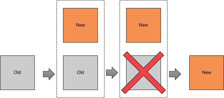
Figure 9.2 When create_before_destroy is set to true, the replacement resource is created before the old resource is destroyed. This means you don’t experience any downtime during force-new updates.
Note create_before_destroy doesn’t default to true because many providers do not allow two instances of the same resource to exist simultaneously. For example, you can’t have two S3 buckets with the same name.
Paul Hinzie, director of engineering at HashiCorp, suggested back in 2015 that the create_before_destroy flag could be used to enable ZDDs (see http://mng.bz/EV1o). Consider the following snippet, which modifies the lifecycle of an aws _instance resource by setting the create_before_destroy flag to true:
resource "aws_instance" "instance" {
  ami           = var.ami
  instance_type = "t3.micro"

  lifecycle {
    create_before_destroy = true
  }

  user_data = <<-EOF
    #!/bin/bash
    mkdir -p /var/www && cd /var/www
    echo "App v${var.version}" >> index.html
    python3 -m http.server 80
  EOF
}
As before, any changes to one of the force-new attributes will trigger a force-new update—but because create_before_destroy is now set to true, the replacement resource will be created before the old one is destroyed. This applies only to managed resources (i.e., not data sources).
Suppose var.version, a variable denoting the application version, were incremented from 1.0 to 2.0. This change would trigger a force-new update on aws _instance because it alters user_data, which is a force-new attribute. Even with create_before_destroy set to true, however, we cannot guarantee that the HTTP server will be running after the resource has been marked as created. In fact, it probably won’t be, because Terraform manages things that it knows about (the EC2 instance) and not the application that runs on that instance (the HTTP server).
We can circumvent this limitation by taking advantage of resource provisioners. Due to the way provisioners were implemented, a resource is not marked as created or destroyed unless all creation-time and destruction-time provisioners have executed with no errors. This means we can use a local-exec provisioner to perform creation-time health checks to ensure that the instance has been created and the application is healthy and serving HTTP traffic:
resource "aws_instance" "instance" {
  ami           = var.ami
  instance_type = "t3.micro"

  lifecycle {
    create_before_destroy = true
  }

  user_data = <<-EOF
    #!/bin/bash
    mkdir -p /var/www && cd /var/www
    echo "App v${var.version}" >> index.html
    python3 -m http.server 80
  EOF

  provisioner "local-exec" {                              ❶
    command = "./health-check.sh ${self.public_ip}"
  }
}
❶ Application health check. The script file health-check.sh is presumed to exist.
Note The self object within a local-exec provisioner is a reference to the current resource the provisioner is attached to.
9.1.2 Additional considerations
Although it would appear that create_before_destroy is an easy way to perform ZDDs, it has a number of quirks and shortcomings that you should keep in mind:
-
Confusing—Once you start messing with Terraform’s default behavior, it’s harder to reason about how changes to your configuration files and variables will affect the outcome of an
apply. This is especially true whenlocal-execprovisioners are thrown in the mix. -
Redundant—Everything you can accomplish with
create_before_destroycan also be done with two Terraform workspaces or modules. -
Namespace collisions—Because both the new and old resources must exist at the same time, you have to choose parameters that will not conflict with each other. This is often awkward and sometimes even impossible, depending on how the parent provider implemented the resource.
-
Force-new vs. in place—Not all attributes force the creation of a new resource. Some attributes (like tags on AWS resources) are updated in place, which means the old resource is never actually destroyed but merely altered. This also means any attached resource provisioners won’t be triggered.
TIP I do not use create_before_destroy as I have found it to be more trouble than it is worth.
9.2 Blue/Green deployments
During a Blue/Green deployment, you switch between two production environments: one called Blue and one called Green. Only one production environment is live at any given time. A router directs traffic to the live environment and can be either a load balancer or a DNS resolver. Whenever you want to deploy to production, you first deploy to the idle environment. Then, when you are ready, you switch the router from pointing to the live server to pointing to the idle server—which is already running the latest version of the software. This switch is referred to as a cutover and can be done manually or automatically. When the cutover completes, the idle server becomes the new live server, and the former live server is now the idle server (see figure 9.3).
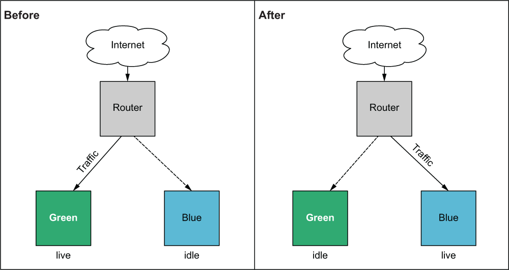
Figure 9.3 Blue/Green deployments have two production environments: one live and serving production traffic and the other idle. Changes are always made first to the idle environment. After cutover, the idle environment becomes the new live environment and begins receiving production traffic.
Blue/Green deployments are the oldest and most popular way to achieve ZDDs. More advanced implementations of ZDD include rolling Blue/Green and/or canary deployments.
While it is certainly possible to do rolling Blue/Green and canary deployments with Terraform, much of the challenge depends on the kind of service you are deploying. Some managed services make this easy because the logic is baked right into the resource (such as with Azure virtual machine scale sets), while other resources need you to implement this logic yourself (such as with AWS Route 53 and AWS application load balancers). This section sticks with the classic, and more general, Blue/Green deployment problem.
9.2.1 Architecture
Going back to the definition of Blue/Green, we need two copies of the production environment: Blue and Green. We also need some common infrastructure that is independent of the environment, such as the load balancer, VPC, and security groups. For the purposes of this exercise, I refer to this common infrastructure as the base because it forms the foundation layer onto which the application will be deployed, similar to what we did with the two-stage deployment technique in chapters 7 and 8.
Note Managing stateful data for Blue/Green deployments is notoriously tricky. Many people recommend including databases in the base layer so that all production data is shared between Blue and Green.
We will deploy version 1.0 of our software onto Green and version 2.0 onto Blue. Initially, Green will be the live server while Blue is idle. Next, we will manually cut over from Green to Blue so that Blue becomes the new live server while Green is idle. From the user’s perspective, the software update from version 1.0 to 2.0 happens instantaneously. The overarching deployment strategy is illustrated by figure 9.4. Figure 9.5 shows a detailed architecture diagram.

Figure 9.4 The shared, or base, infrastructure is deployed first. Initially, Green will be the live server, while Blue is idle. Then a manual cutover will take place so that Blue becomes the new live server. The end result is that the customer experiences an instantaneous software update from version 1.0 to 2.0.
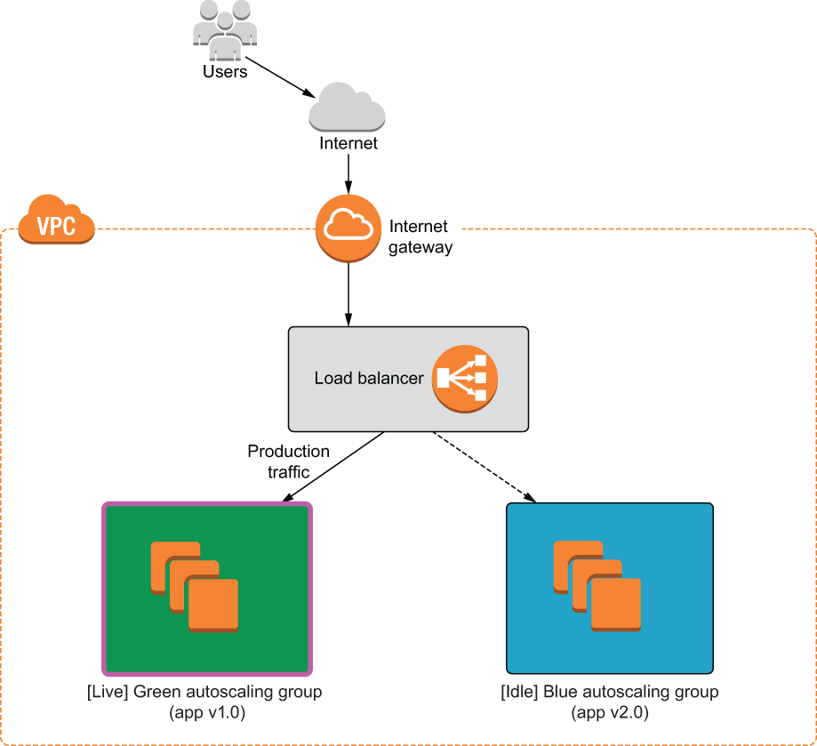
Figure 9.5 We will deploy a load balancer with two autoscaling groups: Green and Blue. The load balancer serves production traffic to the current live environment.
9.2.2 Code
We will use premade modules so we can focus on the big picture. Create a new Terraform workspace, and copy the code from the following listing into a file named blue_green.tf.
provider "aws" {
  region  = "us-west-2"
}

variable "production" {
  default = "green"
}

module "base" {
  source     = "terraform-in-action/aws/bluegreen//modules/base"
  production = var.production
}

module "green" {
  source      = "terraform-in-action/aws/bluegreen//modules/autoscaling"
  app_version = "v1.0"
  label       = "green"
  base        = module.base
}

module "blue" {
  source      = "terraform-in-action/aws/bluegreen//modules/autoscaling"
  app_version = "v2.0"
  label       = "blue"
  base        = module.base
}

output "lb_dns_name" {
  value = module.base.lb_dns_name
}
TIp You can also use feature flags to enable/disable Blue/Green environments. For example, you could have a boolean variable called enable_green_application that set the count attribute on a resource to either 1 or 0 (i.e., count = var.enable_green_application ? 1 : 0).
9.2.3 Deploy
Initialize the Terraform workspace with terraform init, and follow it up with terraform apply. The result of the execution plan is as follows:
$ terraform apply
...
  + resource "aws_iam_role_policy" "iam_role_policy" {
      + id     = (known after apply)
      + name   = (known after apply)
      + policy = jsonencode(
            {
              + Statement = [
                  + {
                      + Action   = "logs:*"
                      + Effect   = "Allow"
                      + Resource = "*"
                      + Sid      = ""
                    },
                ]
              + Version   = "2012-10-17"
            }
        )
      + role   = (known after apply)
    }

Plan: 39 to add, 0 to change, 0 to destroy.

Changes to Outputs:
  + lb_dns_name = (known after apply)

Do you want to perform these actions?
  Terraform will perform the actions described above.
  Only 'yes' will be accepted to approve.

  Enter a value:
Confirm, and wait until Terraform finishes creating the resources (approximately 5-10 minutes). The output of the apply will contain the address of the load balancer, which can be used to access the current live autoscaling group. Recall that in this case, it is Green:
module.green.aws_autoscaling_group.webserver: Still creating... [40s elapsed]
module.green.aws_autoscaling_group.webserver: Creation complete after 42s
[id=terraforminaction-v7t08a-green-asg]
module.blue.aws_autoscaling_group.webserver: Creation complete after 48s
[id=terraforminaction-v7t08a-blue-asg]

Apply complete! Resources: 39 added, 0 changed, 0 destroyed.

Outputs:

lb_dns_name = terraforminaction-v7t08a-lb-369909743.us-west-2.elb.amazonaws.com
Navigate to the address in the browser to pull up a simple HTML site running version 1.0 of the application on Green (see figure 9.6).
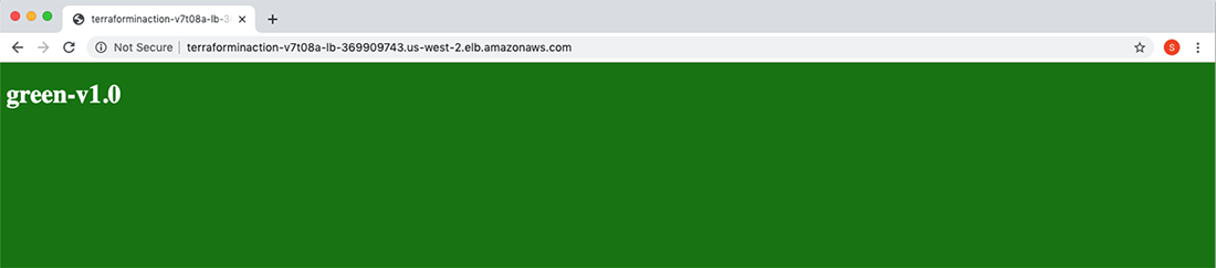
Figure 9.6 The application load balancer currently points to the Green autoscaling group, which hosts version 1.0 of the application.
9.2.4 Blue/Green cutover
Now we are ready for the manual cutover from Green to Blue. Blue is already running version 2.0 of the application, so the only thing we need to do is update the load-balancer listener to point from Green to Blue. In this example, it’s as easy as changing var.production from "green" to "blue".
provider "aws" {
  region  = "us-west-2"
}

variable "production" {
  default = "blue"
}

module "base" {
  source     = "terraform-in-action/aws/bluegreen//modules/base"
  production = var.production
}

module "green" {
  source      = "terraform-in-action/aws/bluegreen//modules/autoscaling"
  app_version = "v1.0"
  label       = "green"
  base        = module.base
}

module "blue" {
  source      = "terraform-in-action/aws/bluegreen//modules/autoscaling"
  app_version = "v2.0"
  label       = "blue"
  base        = module.base
}

output "lb_dns_name" {
  value = module.base.lb_dns_name
}
$ terraform apply
...
      ~ action {
            order            = 1
          ~ target_group_arn = "arn:aws:elasticloadbalancing:us-west-2:215974853022:targetgroup/terraforminaction-v7t08a-blue/7e1fcf9eb425ac0a" -> "arn:aws:elasticloadbalancing:us-west-2:215974853022:targetgroup/terraforminaction-v7t08a-green/80db7ad39adc3d33"
            type             = "forward"
        }

        condition {
            field  = "path-pattern"
            values = [
                "/stg/*",
            ]
        }
    }

Plan: 0 to add, 2 to change, 0 to destroy.

Do you want to perform these actions?
  Terraform will perform the actions described above.
  Only 'yes' will be accepted to approve.

  Enter a value:
After you confirm the apply, it should take only a few seconds for Terraform to complete the action. Again, from the user’s perspective, the change happens instantaneously with no discernable downtime. The load-balancer address has not changed: all that has happened is that the load balancer is now serving traffic to the Blue autoscaling group rather than Green. If you refresh the page, you will see that version 2.0 of the application is now in production and is served by the Blue environment (see figure 9.7).
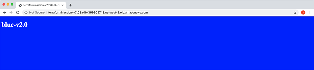
Figure 9.7 The load balancer now points to the Blue autoscaling group, which hosts version 2.0 of the application.
9.2.5 Additional considerations
We have demonstrated a simple example of how to do Blue/Green deployments with Terraform. You should take the following additional considerations into account before implementing Blue/Green for your deployments:
-
Cost savings—The idle group does not need to be exactly the same as the active group. You can save money by scaling down the instance size or the number of nodes when not needed. All you have to do is scale up right before you make the cutover.
-
Reducing the blast radius—Instead of having the load balancer and autoscaling groups all in the same Terraform workspace, it may be better to have three workspaces: one for Blue, one for Green, and one for the base. When performing the manual cutover, you mitigate risk by not having all your infrastructure in the same workspace.
-
Canary deployments—With AWS Route 53, you can perform canary deployments by having two load balancers and routing a percentage of the production traffic to each. Note that this may require executing a series of incremental Terraform deployments.
WARNIng Remember to take down your infrastructure with terraform destroy before proceeding, to avoid incurring ongoing costs!
9.3 Configuration management
Occasionally, it’s important to step back and ask, “Is Terraform the right tool for the job?” In many cases, the answer is no. Terraform is great, but only for the purpose it was designed for. For application deployments on VMs, you would be better served with a configuration management tool.
The further you move up the application stack, the more frequently changes occur. At the bottom is the infrastructure, which is primarily static and unchanging. By comparison, applications deployed onto that infrastructure are extremely volatile. Although Terraform can deploy applications (as we have seen in previous chapters), it isn’t particularly good at continuous deployment. By design, Terraform is an infrastructure-provisioning tool and is too slow and cumbersome to fit this role. Instead, a container-orchestration platform or configuration-management tool would be more appropriate. Since we examined application delivery with containers in the preceding two chapters, let’s now consider configuration management.
Configuration management (CM) enables rapid software delivery onto existing servers. Some CM tools can perform a degree of infrastructure provisioning, but none are particularly good at the task. Terraform is much better at infrastructure provisioning than any existing CM tool. Nevertheless, it’s not a competition: you can achieve great results by combining the infrastructure-provisioning capabilities of Terraform with the best parts of CM.
Superficially, it might seem that the innate mutability of CM clashes with the innate immutability of Terraform, but this isn’t so. First, we know that Terraform is not as immutable as it claims to be: in-place updates and local-exec provisioners are examples to the contrary. Second, CM is not as mutable as you might be led to believe. Yes, CM relies on mutable infrastructure, but applications can be deployed onto that infrastructure immutably.
Terraform and CM tools do not have to be competitive and can be integrated effectively into a common workflow. When you use the two-stage deployment technique, Terraform can provision the infrastructure, and CM can handle application delivery (see figure 9.8).
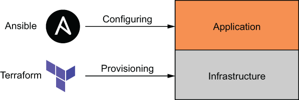
Figure 9.8 A two-stage deployment, with Terraform deploying the base-level infrastructure and Ansible configuring the application
9.3.1 Combining Terraform with Ansible
Ansible and Terraform make a great pair, and HashiCorp has even publicly stated that they are “better together” (see http://mng.bz/N8eN). But how can these two disparate tools be successfully integrated in practice? It works like this:
This process is illustrated in figure 9.9 when the target cloud is AWS and the VM in question is an EC2 instance.
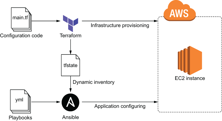
Figure 9.9 Terraform provisions an EC2 instance, and Ansible configures it with an Ansible playbook.
Note Chef, Puppet, and SaltStack could be incorporated in a similar manner.
For this scenario, we are going to provision a single EC2 instance with Terraform. The EC2 instance will have Ansible preinstalled on it and will be configured with an SSH key pair generated through Terraform. Once the server is up and running, we will deploy an Nginx application onto it with Ansible. Finally, we will update the application to simulate a new application deployment.
9.3.2 Code
Jumping right in, we’ll start by declaring the AWS provider. In a new project directory, create a main.tf file with the AWS provider declared at the top.
provider "aws" {
  region  = "us-west-2"
}
Next, we’ll generate the SSH key pair that we’ll use to configure the EC2 instance. The TLS provider makes this easy. After that, we’ll write the private key to a local file and upload the public key to AWS (see listing 9.4).
Note Ansible requires SSH access to push software updates. Instead of creating a new SSH key pair, you could reuse an existing one, but it’s good to know how to do this with Terraform, regardless.
...
resource "tls_private_key" "key" {
  algorithm = "RSA"
}

resource "local_file" "private_key" {
  filename          = "${path.module}/ansible-key.pem"
  sensitive_content = tls_private_key.key.private_key_pem
  file_permission   = "0400"
}

resource "aws_key_pair" "key_pair" {
  key_name   = "ansible-key"
  public_key = tls_private_key.key.public_key_openssh
}
Configuring SSH means we need to create a security group with access to port 22. Of course, we also need port 80 open to serve HTTP traffic. The configuration code for the AWS security group is shown next.
...
data "aws_vpc" "default" {
  default = true
}

resource "aws_security_group" "allow_ssh" {
  vpc_id = data.aws_vpc.default.id

  ingress {
    from_port   = 22
    to_port     = 22
    protocol    = "tcp"
    cidr_blocks = ["0.0.0.0/0"]
  }

  ingress {
    from_port   = 80
    to_port     = 80
    protocol    = "tcp"
    cidr_blocks = ["0.0.0.0/0"]
  }

  egress {
    from_port   = 0
    to_port     = 0
    protocol    = "-1"
    cidr_blocks = ["0.0.0.0/0"]
  }
}
We also need to get the latest Ubuntu AMI so that we can configure the EC2 instance. This code should be familiar.
...
data "aws_ami" "ubuntu" {
  most_recent = true

  filter {
    name   = "name"
    values = ["ubuntu/images/hvm-ssd/ubuntu-focal-20.04-amd64-server-*"]
  }

  owners = ["099720109477"]
}
And now we can configure the EC2 instance.
...

resource "aws_instance" "ansible_server" {
  ami                    = data.aws_ami.ubuntu.id
  instance_type          = "t3.micro"
  vpc_security_group_ids = [aws_security_group.allow_ssh.id]
  key_name               = aws_key_pair.key_pair.key_name

  tags = {
    Name = "Ansible Server"
  }

  provisioner "remote-exec" {                                              ❶
    inline = [
      "sudo apt update -y",
      "sudo apt install -y software-properties-common",
      "sudo apt-add-repository --yes --update ppa:ansible/ansible",
      "sudo apt install -y ansible"
]

    connection {
      type        = "ssh"
      user        = "ubuntu"
      host        = self.public_ip
      private_key = tls_private_key.key.private_key_pem
    }
  }

  provisioner "local-exec" {                                               ❷
    command = "ansible-playbook -u ubuntu --key-file ansible-key.pem -T 300
    ➥ -i '${self.public_ip},', app.yml"
  }
}
Note The remote-exec provisioner is exactly like a local-exec provisioner, except it first connects to a remote host.
Finally, we need to output the public_ip and the Ansible command for running the playbook.
...
output "public_ip" {
 value = aws_instance.ansible_server.public_ip
}

output "ansible_command" {
    value = "ansible-playbook -u ubuntu --key-file ansible-key.pem -T 300
    ➥ -i '${aws_instance.ansible_server.public_ip},', app.yml"
}
At this point, the Terraform is done, but we still need a couple more files for Ansible. In particular, we need a playbook file (app.yml) and an index.html file that will serve as our sample application.
Note If you do not already have Ansible installed on your local machine, you should install it at this point. The Ansible documentation describes how to do this: http://mng.bz/D1Nn.
Create a new app.yml playbook file with the contents from the next listing. This is a simple Ansible playbook that ensures that Nginx is installed, adds an index.html page, and starts the Nginx service.
---
    - name: Install Nginx
      hosts: all
      become: true

      tasks:
      - name: Install Nginx
        yum:
          name: nginx
          state: present

      - name: Add index page
        template:
          src: index.html
          dest: /var/www/html/index.html

      - name: Start Nginx
        service:
          name: nginx
          state: started
And here is the HTML page we’ll be serving.
<!DOCTYPE html>
<html>
<style>
    body {
        background-color: green;
        color: white;
    }
</style>

<body>
    <h1>green-v1.0</h1>
</body>

</html>
Your current directory now contains the following files:
.
├── app.yml
├── index.html
├── main.tf
For reference, here are the complete contents of main.tf.
provider "aws" {
  region  = "us-west-2"
}

resource "tls_private_key" "key" {
  algorithm = "RSA"
}

resource "local_file" "private_key" {
  filename          = "${path.module}/ansible-key.pem"
  sensitive_content = tls_private_key.key.private_key_pem
  file_permission   = "0400"
}

resource "aws_key_pair" "key_pair" {
  key_name   = "ansible-key"
  public_key = tls_private_key.key.public_key_openssh
}

data "aws_vpc" "default" {
  default = true
}

resource "aws_security_group" "allow_ssh" {
  vpc_id = data.aws_vpc.default.id

  ingress {
    from_port   = 22
    to_port     = 22
    protocol    = "tcp"
    cidr_blocks = ["0.0.0.0/0"]
  }

  ingress {
    from_port   = 80
    to_port     = 80
    protocol    = "tcp"
    cidr_blocks = ["0.0.0.0/0"]
  }

  egress {
    from_port   = 0
    to_port     = 0
    protocol    = "-1"
    cidr_blocks = ["0.0.0.0/0"]
  }
}

data "aws_ami" "ubuntu" {
  most_recent = true

  filter {
    name   = "name"
    values = ["ubuntu/images/hvm-ssd/ubuntu-focal-20.04-amd64-server-*"]
  }

  owners = ["099720109477"]
}

resource "aws_instance" "ansible_server" {
  ami                    = data.aws_ami.ubuntu.id
  instance_type          = "t3.micro"
  vpc_security_group_ids = [aws_security_group.allow_ssh.id]
  key_name               = aws_key_pair.key_pair.key_name

  tags = {
    Name = "Ansible Server"
  }

  provisioner "remote-exec" {
    inline = [
      "sudo apt update -y",
      "sudo apt install -y software-properties-common",
      "sudo apt-add-repository --yes --update ppa:ansible/ansible",
      "sudo apt install -y ansible"
]

    connection {
      type        = "ssh"
      user        = "ubuntu"
      host        = self.public_ip
      private_key = tls_private_key.key.private_key_pem
    }
  }

  provisioner "local-exec" {
    command = "ansible-playbook -u ubuntu --key-file ansible-key.pem -T 300
    ➥ -i '${self.public_ip},', app.yml"
  }
}

output "public_ip" {
 value = aws_instance.ansible_server.public_ip
}

output "ansible_command" {
    value = "ansible-playbook -u ubuntu --key-file ansible-key.pem -T 300
    ➥ -i '${aws_instance.ansible_server.public_ip},', app.yml"
}
9.3.3 Infrastructure deployment
Warning Ansible (v2.9 or later) must be installed on your local machine or the local-exec provisioner will fail!
Initialize Terraform, and perform a terraform apply:
$ terraform init && terraform apply -auto-approve
...
aws_instance.ansible_server: Creation complete after 2m7s
[id=i-06774a7635d4581ac]

Apply complete! Resources: 5 added, 0 changed, 0 destroyed.

Outputs:

ansible_command = ansible-playbook -u ubuntu --key-file ansible-key.pem -T
300 -i '54.245.143.100,', app.yml
Now that the EC2 instance has been deployed and the first Ansible playbook has run, we can view the web page by navigating to the public IP address in the browser (see figure 9.10).

Figure 9.10 Green application deployment performed with Ansible
9.3.4 Application deployment
We did not need to use a local-exec provisioner to deploy the initial Ansible playbook, but it was a good example of when local-exec provisioners might be useful. Usually, application updates are deployed independently, perhaps as the result of a CI trigger. To simulate an application change, let’s modify index.html as shown next.
<!DOCTYPE html>
<html>
<style>
    body {
        background-color: blue;
        color: white;
    }
</style>

<body>
    <h1>blue-v2.0</h1>
</body>

</html>
By re-running the Ansible playbook, we can update the application layer without touching the underlying infrastructure (see figure 9.11).

Figure 9.11 Terraform provisions initial infrastructure, while Ansible deploys applications onto that infrastructure.
Let’s deploy the update now by running the ansible-playbook command from the Terraform output:
$ ansible-playbook -u ubuntu --key-file ansible-key.pem -T 300 -i
'54.245.143.100,', app.yml

PLAY [Install Nginx]
***************************************************************************
***************************************************************************
*************************************************************

TASK [Gathering Facts]
***************************************************************************
***************************************************************************
***********************************************************
ok: [54.245.143.100]

TASK [Install Nginx]
***************************************************************************
***************************************************************************
*************************************************************
ok: [54.245.143.100]

TASK [Add index page]
***************************************************************************
***************************************************************************
************************************************************
changed: [54.245.143.100]

TASK [Start Nginx]
***************************************************************************
***************************************************************************
***************************************************************
ok: [54.245.143.100]

PLAY RECAP
***************************************************************************
***************************************************************************
***********************************************************************
54.245.143.100             : ok=4    changed=1    unreachable=0    failed=0
skipped=0    rescued=0    ignored=0
TIP If you have more than one VM, it’s better to write the addresses to a dynamic inventory file. Terraform can generate this file for you by way of string templates and the Local provider.
Now that Ansible has redeployed our application, we can verify that the changes have propagated by refreshing the web page (see figure 9.12).
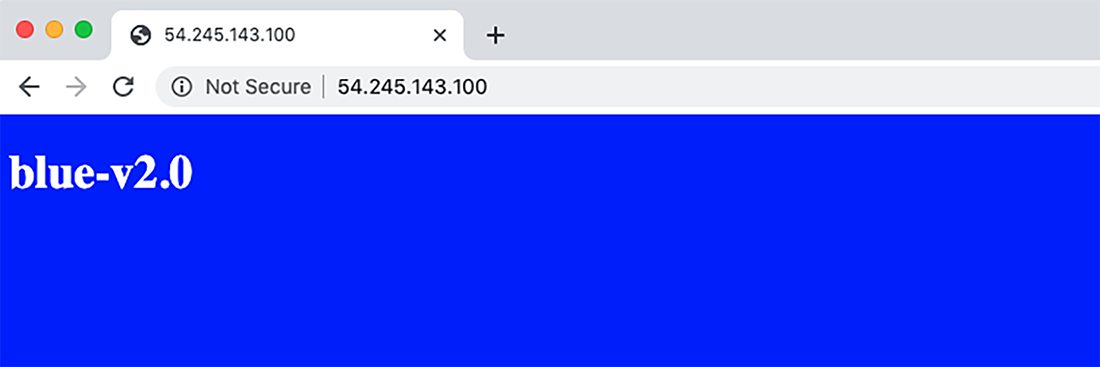
Figure 9.12 Blue application deployment performed by Ansible
We have demonstrated how to combine Terraform with Ansible. Instead of worrying about how to perform ZDD with Terraform, we have offloaded the responsibility to Ansible—and we can do the same thing with any other configuration-management or application-delivery technology.
Warning Don’t forget to clean up with terraform destroy!
9.4 Fireside chat
This chapter focused on zero-downtime deployment and what that means from a Terraform perspective. We started by talking about the lifecycle block and how it can be used alongside local-exec health checks to ensure that a new service is running before we tear down the old service. The lifecycle block is the last of the resource meta attributes; the complete list is as follows:
-
count—Creates multiple resource instances, indexable with bracket notation -
for_each—Creates multiple instances from a map or set of strings -
provisionerandconnection—Takes extra actions after resource creation
Traditionally, ZDD refers to application deployments: Blue/Green, rolling Blue/Green, or canary deployments. Although it’s possible to use the lifecycle block to mimic the behavior of Blue/Green deployments, doing so is confusing and not recommended. Instead, we used feature flags to switch between environments with Terraform.
Finally, we explored how to offload the responsibilities of ZDD to other, more suitable technologies (specifically, Ansible). Yes, Terraform can deploy your entire application stack, but this isn’t always convenient or prudent. Instead, it may be beneficial to use Terraform only for infrastructure provisioning and a proven CM tool for application delivery. Of course, there isn’t one right choice. It all depends on what you are deploying and what serves your customers the best.
Summary
-
The
lifecycleblock has many flags that allow for customizing resource lifecycles. Of these, thecreate_before_destroyflag is certainly the most drastic, as it completely overhauls the way Terraform behaves. -
Performing Blue/Green deployments in Terraform is more a technique than a first-class feature. We covered one way to do Blue/Green using feature flags to toggle between the Green and Blue environments.
-
Terraform can be combined with Ansible by using a two-stage deployment technique. In the first stage, Terraform deploys the static infrastructure; in the second stage, Ansible deploys applications on top of that infrastructure.
-
The TLS provider makes it easy to generate SSH key pairs. You can even write out the private key to a .pem file using the Local provider.
-
remote-execprovisioners are no different thanlocal-execprovisioners, except they run on a remote machine instead of the local machine. They output to normal Terraform logs and can be used in place ofuser_initdata or prebaked AMIs.