CHAPTER TWO
The Workings of a Modern Solar Energy System
In order to understand how a solar energy system works, I need to show you how a typical solar cell turns the sun's rays into an electrical current. The radiation emanating from the sun consists of photons. They travel to the earth at the speed of light. When photons hit a solar cell that's part of a solar panel, the silicon in the cell absorbs them. This causes electrons that were happily spinning around on their atomic orbit to get excited. Once a photon strike excites an electron, one of two things happens: The electron can dissipate the energy caused by the strike in the form of heat and return to its orbit, or the electron can move through the cell until it strikes an electrode. That strike generates an electric current. This current flows through the cell layers.
The vital part of the process is the chemical bonds of the various layers. There are usually two layers of silicon, one bonded with phosphorus and the other with boron. The two layers have different electrical charges, one positive and one negative. This difference allows electricity to flow between them as photons strike the surface of the cell. Solar cells create direct current (DC) electricity. Later in this chapter I'll discuss how DC electricity is converted to the alternating current (AC) electricity that we use at home and at work.
HOW POLYCRYSTALLINE SILICON SOLAR CELLS WORK
Scientists used silicon wafers to make the first generation of solar cells. Silicon is a very attractive raw material for solar cells. It has the ability to keep its semiconductor properties at high temperatures. In addition, silicon is abundant; however, purity levels required for both semiconductors and solar cells are very high. Roughly 90 percent of all solar panel applications use polycrystalline silicon solar cells. That's due to the high efficiencies you can achieve with polycrystalline silicon cells, compared to other solar cell technologies.
Figure 2.1 shows the composition of a typical p-n junction, polycrystalline silicon solar cell. The cell consists of four layers. The top layer (represented by the bars) is an antireflective coating. That's needed to keep photons from the sun's rays from reflecting before they can energize electrons. Below that are n-type and p-type silicon. The thin, gray layer conducts electrons. The thin line between the p-type semiconductor and the n-type semiconductor is the p-n junction.

FIGURE 2.1 COMPOSITION OF A TYPICAL p-n JUNCTION, POLYCRYSTALLINE SILICON SOLAR CELL
Data source: en.wikipedia.org/wiki/Solar_cell—/media/File:Silicon_Solar_cell_structure_and_mechanism.svg.
When an n-type semiconductor layer is hit by light in the form of photons, each photon will free exactly one electron. This will leave a free hole. If this happens close by the electric field, it will drive the hole to the p side and the electron to the n side. If, as shown in Figure 2.1, there is an external electrical current path, electrons will flow through that path to the p side to fill holes that the electric field created there. This is a simple representation of the photoelectric effect, and the basic operation of a solar cell.
Individual solar cells are typically about four inches in diameter. A single cell produces 0.5 volts. The typical solar panel contains 96 solar cells connected in series. This produces a panel voltage of 48 volts DC. The panel's efficiency determines the power produced, and can range from 150 watts to 345 watts per panel.
SOLAR CELL MANUFACTURING PROCESS
In this section, I'll cover the manufacturing process and technology associated with polycrystalline silicon cell manufacturing. Later in this chapter, I'll touch on other cell technologies but won't get into other types of cell manufacturing. I believe polycrystalline silicon will remain the dominant cell technology as costs continue to decline.
As mentioned above, every polycrystalline silicon cell has as its base component a silicon wafer. A technician fills an electric carbon arc furnace with raw silicon, in the form of crushed quartz or quartzite gravel. The carbon releases the oxygen trapped in the quartz and the end products are molten silicon, a slag of impurities, and carbon dioxide.
Next, the machine lowers a half-inch diameter length of pure silicon (called the seed) into the molten silicon. It slowly rotates the seed and starts withdrawing a silicon ingot from the molten bath. The withdrawal rate determines the diameter of the resulting mono-crystal silicon ingot.
The silicon ingot is extremely pure. That's because the liquid bath tends to keep impurities in it. A diamond saw mills the ingot into a rectangular or hexagonal shape. This allows maximum space utilization when cells fit together on panels. A second diamond saw cuts the ingot into 0.5-millimeter-thick wafers. Special lapping machines polish the wafers to a mirror finish.
The next step in the cell manufacturing process is to “dope” the wafer. Doping intentionally adds impurities back into the silicon in order to change its electrical properties. Doped silicon is a much better conductor of electricity than pure silicon. Boron and phosphorous are typical dopants used on wafers destined to become solar cells.
From this point forward, the process is highly automated. Robots place wafers in a furnace. It heats them to 1,410°C (2,570°F), just below silicon's melting point. The furnace computer then introduces a small amount of phosphorous gas into the furnace chamber. The phosphorous atoms diffuse into the silicon as it is close to liquefying. The amount of phosphorous, temperature, and time are all carefully controlled. This creates a uniform diffusion depth. This process is very similar to doping processes used in the semiconductor industry.
The wafers then transfer to a screening machine. This machine screens thin lines of silver paste onto the wafers to create electrical connections on the front and back of the wafer. The final step is to heat the wafers in a furnace to temperatures ranging from 750–900°C (1,382–1,652°F). This firmly connects the silver to the front and back of the wafer. The lines have to be thin so as not to block sunlight to the cell surface.
The next step is to cover the cell surface with an antireflective coating. Pure silicon has a mirror-like finish and can reflect up to 35 percent of the incoming sunlight. This coating is typically silicon oxide or titanium dioxide. There are a number of different processes used to deposit this coating. The silicon wafers of the newest cells have a pyramid-shaped, grainy surface (Figure 2.2). These conduct as much as 70 percent of the available light. Scientists are using nanotechnology as a means to increase the surface area of a silicon wafer.

FIGURE 2.2 SCANNING ELECTRON MICROSCOPE PHOTOGRAPH OF A TEXTURED SILICON SURFACE
Source: UNSW Photovoltaic and Renewable Energy Engineering. Reproduced with permission.
Finally, robots connect the finished cells to make a string of 36 or more. A tough glass top surface and a plastic back encapsulate the complete solar module. Glue attaches the module to an aluminum frame to allow mounting on rooftops or ground-mount assemblies.
SOLAR CELL AND MODULE EFFICIENCIES
The efficiency of a solar cell refers to the amount of sunlight the cell can convert into electricity. There are a number of factors that determine overall cell efficiency. Reflectance efficiency is a measure of the amount of light reflected back into the atmosphere from the cell surface.
The thermodynamic efficiency is a measure of the amount of sunlight converted by the cell into electricity. The absolute maximum theoretically possible limit is 86 percent. However, in practice, limits for different technologies are far lower than that. For instance, a single junction silicon cell has a maximum thermodynamic efficiency limit of 31 percent.
Other factors affecting the overall efficiency of a solar cell are conduction efficiency and charge carrier separation efficiency. These parameters are difficult to measure, and their description is beyond the scope of this book.
The current world record for solar cell efficiency was set in December 2014. A multi-junction, light-concentrating solar cell achieved the remarkable efficiency of 46 percent. Scientists achieved this through the collaborative efforts of Fraunhofer ISE (Germany), CEA-Leti (France), and Soitec (France).
However, most solar cells used in today's photovoltaic systems have just one junction. This means they have a lower efficiency limit called the ultimate efficiency. Photons that are outside of the absorption range of the surface material cannot generate a flow of electrons that produces electricity. Instead, the light energy converts to heat. The ultimate efficiency for a single junction silicon photovoltaic cell is approximately 34 percent.
In February 2016, SunPower Corporation set a new record for solar module efficiency. In a National Renewable Energy Laboratory (NREL)–certified test, SunPower's latest module is 22.8 percent efficient. Then in June 2016, SunPower broke its own record introducing a module with an NREL-validated result of 24.1 percent. In March 2018, SunPower started selling its 22.8 percent efficient panels commercially.1 There is absolutely no question in my mind that by the time you read this, this record will most certainly have been broken, either by SunPower or some other panel manufacturer. Technology marches on.
SOLAR PANEL MANUFACTURING
In order to make a solar panel, you must connect multiple solar cells together. The solar panel manufacturing process is highly automated. The modern solar-manufacturing plant employs robots, conveyors, and other automated machinery to lay out and construct each solar panel. To minimize contaminants, which could cause premature failure of the panel, the entire process happens in cleanroom conditions.
The first step in the process is to solder as many as 10 cells together into a string. This creates an electrical connection between the cells. Strings of cells are laid out in the form of a rectangular matrix containing 48, 60, or 72 cells. The next step is to connect the individual strings together via soldering.
The automated assembly line moves the cell matrix between two sheets of a special encapsulant. The assembly then moves to the next station, where one robot places a tough glass sheet over the top. A second robot places a highly durable backsheet made from a polymer-based material under the bottom encapsulant. The polymer backsheet has an access hole milled in it to allow the electrical conductors from the cell matrix to connect to a junction box. Heaters gently warm the entire assembly to activate both sheets of encapsulant. Slight pressure forces all layers together to create a complete encapsulation of the cell matrix. This protects them from harsh winter and summer weather.
Finally, a robot flips the assembly upside-down, and epoxies the junction box to the rear of the access hole and connects it electrically to the cell matrix. Robots then place a rigid aluminum frame around the entire assembly. They apply a waterproof glue to bond it to the glass surface. This provides structural rigidity to the panel, and facilitates mounting on a roof or ground-mounted racking system. The panel then proceeds to quality assurance testing and packaging for delivery.
THE PLUNGING COST OF SOLAR
One amazing graph tells the tale of solar and its future (see Figure 2.3). In 1975, solar energy production was primarily used by NASA to power satellites. Early solar cells were only about 4 percent efficient, and they were very expensive to make. At the time, no one seriously considered that polycrystalline silicon solar would ever develop into a serious mainstream energy source.
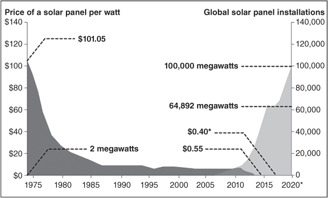
FIGURE 2.3 PRICE OF SOLAR PANELS IN WATTS AND TOTAL GLOBAL SOLAR INSTALLATION IN MEGAWATTS
Source: www.treehugger.com/renewable-energy/striking-chart-showing-solar-power-will-take-over-world.html and new data from: www.greentechmedia.com/articles/read/gtm-research-global-solar-pv-installations-grew-34-in-2015 and cleantechnica.com/2015/01/29/solar-costs-will-fall-40-next-2-years-heres/.
Engineers had to develop processes to purify silicon to a very high level. They then had to grow it into single crystal silicon ingots. Special saws cut each ingot into thin silicon wafers. Other machines polished them to a very smooth mirror-like finish. At the time, each cell produced just 0.5 watts of power. Connecting enough cells together and somehow creating solar panels at a reasonable price seemed impossible.
As the cost of semiconductor wafers dropped over the next several decades, however, so did the cost of manufacturing solar cells. After all, a solar cell is just one giant semiconductor device. As prices dropped, cell efficiencies improved, too. Solar cells in production today have efficiencies as high as 24 percent. Back in 1975, solar panels cost $101.05 per watt of power produced. In October 2015, SolarCity announced a panel that produces power for $0.55 per watt.2 But panels are going to get even cheaper. The International Renewable Energy Association predicts that prices will fall to $0.40 per watt by the end of 2017 or so.3 Most large manufacturers are improving (reducing) cost per watt by 1–2 cents every quarter. It's certainly reasonable to think they'll reach $0.40 by the time this book is published.
A graph like the one shown in Figure 2.3 is quite familiar to any entrepreneur who's tried to launch a new product. The proof of concept phase is on the far left. The valley in between, often referred to in business as the “valley of death,” can be longer and wider than a product developer's pockets. In the case of solar, it took three decades for the industry to really enter a viable commercial market.
The year 2000 was a notable one for the nascent solar industry. It had finally surpassed total panel production of 1 GW. That's the equivalent of a large, conventional coal or natural gas-fired power plant. By 2003, the solar industry was using more silicon wafer real estate than the semiconductor industry. Just four short years after it hit 1 GW of total panel production, the solar industry was producing 1-GW-worth of panels annually.
In just the past 10 years, solar installations have skyrocketed from about 5 GW of installed capacity worldwide to over 65 GW. Solar energy quickly became a mainstream option for utilities considering new capacity. A virtuous cycle of favorable government policies fueled increased installations. That drove manufacturers to invest in highly automated manufacturing lines, which drove costs down even more. That created even more demand and even lower prices, and so on.
It turns out there is a “Moore's law” for solar. It's Swanson's law, in honor of Richard Swanson. He is the founder of SunPower Corporation. Swanson's law states that every time there is a doubling of panel production and shipment, there is a 20 percent drop in panel costs. Swanson wrote a paper on this relationship back in 2006. Figure 2.4 is a chart depicting Swanson's law.

FIGURE 2.4 SWANSON'S LAW FOR PHOTOVOLTAICS
Source: en.wikipedia.org/wiki/Swanson%27s_law#/media/File:Swansons-law.png and updated with additional data provided by author.
As you can see from the figure, module costs have generally followed Swanson's law. In fact, by the end of 2015, panel costs had dropped to $0.55 per watt. By 2018, panel costs dropped to $0.37 per watt. By 2022, GTM Research projects that solar panel manufacturing costs will drop to $0.24 per watt. That's a drop of more than 100 percent in just seven years.4 However, panel prices have fallen so far that they now represent less than half the total cost of a complete solar system at both the residential and utility scale. Most of the system now comprises soft costs. These are the inverters that change the direct current (DC) power into alternating current (AC) power that is grid-compatible. In addition to inverters, mounting hardware, grid connection fees and labor are also part of the soft costs.
From the present forward, it is now more appropriate to ask what is the cost reduction trend of solar-produced electricity. There will still be additional reductions in the cost of solar panels. But overall system costs, especially at the utility-scale level, will have the biggest impact on the cost of solar electricity.
For large utility-scale systems, having an executed Power Purchase Agreement (PPA) in place is almost a necessity before the system is constructed. A PPA is a long-term (usually 20 years) contract between the entity generating electricity (the seller) and a second party looking to purchase electricity (the buyer). The seller is generally the builder or developer of the utility-scale plant. The buyer is usually a utility; however, it may also be a building occupant, a government entity, a school, or a business.
Utility-scale solar installations are becoming increasingly popular. Due to the lack of a national energy plan, many states have passed renewable energy mandates. These require utilities to obtain a certain percentage of their power from renewable sources. The easiest way for utilities to comply is by executing PPAs with utility-scale solar plant developers. Banks or other entities providing financing for utility-scale projects almost always require that an executed PPA be in place before any money will be lent to build a project.
When it comes to PPAs, the seller typically seeks non-recourse project financing for the utility-scale project. This limits the seller's liability to the value of the project and the electricity produced. The PPA has clear definitions that define the expected power output of the solar project, and its associated revenue stream. In addition, the Federal Energy Regulatory Commission (FERC) regulates and reviews all PPAs in the United States.
Developers price PPAs in dollars per megawatt-hour (MWh) produced. As solar system prices have come down, so too have PPA prices, as seen in Figure 2.5.

FIGURE 2.5 LEVELIZED US UTILITY-SCALE PPA PRICES
Under the typical PPA, the seller is responsible for operation and maintenance of the utility-scale project. This typically includes regular inspections, any panel replacements if necessary, and cleaning of the panel surfaces. The seller is also required to install and maintain a metering device that measures the real-time and cumulative power output data. This is typically an automated system that the purchaser can access anytime.
The PPA also delineates the delivery point of the power (i.e. where the sale point is relative to the buyer and seller's location). With solar PPAs, the typical delivery is a busbar sale or delivery. That means the actual delivery point is located on the transmission, or high side, of the transformer at the project site. In this case, the buyer is responsible for transmitting the purchased electricity from the seller's location.
The price for solar energy keeps hitting new lows. Lower installation costs and better utility-scale project performance are the two big cost-reduction drivers. The current average for PPA pricing is 4¢/kWh.5 By way of comparison, US wholesale electricity prices ranged from 2–4¢/kWh in 2015.6 That puts utility-scale solar right in the middle of the wholesale range, making it an increasingly cost-competitive option for utilities. Since 2009, according to a report published by the Lawrence Berkeley National Laboratory, the installed costs for utility-scale projects are down by 85 percent.
The biggest driver of cost reduction is higher panel efficiencies. As panel efficiencies increase, fewer panels are required for a given level of power output. For a small, home system of 10 KW, it may only mean three or four fewer panels. However, for a 50 to 100 MW utility-scale solar farm, the savings can be dramatic. Even a 1 percent increase in panel efficiency can mean hundreds or thousands of fewer panels on a large system. It also means fewer inverters, less wiring, less racking, and lower installation costs.
As a result of utility-scale solar's lower cost, the pipeline of projects in development just continues to increase. At the end of 2017, the utility-scale solar sector added 6,200 MW of additional utility-scale capacity.7 At the end of 2017, the total installed utility-scale solar stood at roughly 70 GW, or 60 percent of all installed solar capacity.8 The market is showing signs of spreading outside of California, as much of the new capacity is located in the southeast and Texas.
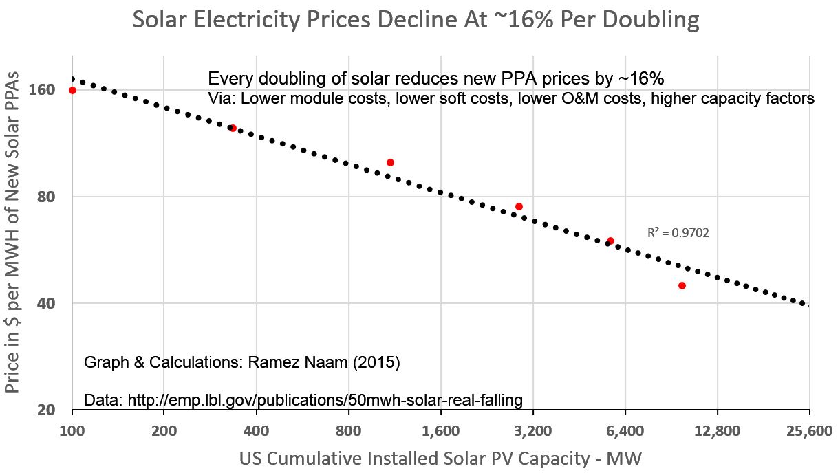
Figure 2.6 comes from a Lawrence Berkeley National Laboratories study. Like every other industrial product, solar is getting cheaper as production scales upward. Figure 2.6 shows a trend in time. In the case of solar PV modules, history has shown that doubling manufacturing capacity has reduced costs by 20 percent. When we look at electricity generated from utility-scale solar systems, we get Figure 2.6.

FIGURE 2.6 SOLAR ELECTRICITY PRICES DECLINE AT 16 PERCENT FOR EVERY DOUBLING OF INSTALLED CAPACITY
Source: rameznaam.com/wp-content/uploads/2015/08/Solar-Full-PPA-and-LCOE-Learning-Curve.jpg.
As we can see from Figure 2.6, every doubling of utility-scale solar generating capacity results in a 16 percent reduction in electricity costs produced by the newest solar installations. I expect that if this study were repeated today (the original was undertaken in May 2015), the rate would be higher than 16 percent. The main takeaway from the Lawrence Berkeley National Laboratories study is that scaling up production of panels and solar generating plants is the key factor in reducing both the costs of solar panels and the electricity they produce.
We'll cover the bright future of solar (pun intended) in Chapter 5. We'll also look at other promising solar cell technologies in that section. In Chapter 3, I'll outline the information you need to determine if solar is right for you and how to calculate the size of the system. Many installations, because of their location, will be stand-alone systems. For the typical homeowner, economics and storage will play a part as to whether tying to the grid makes sense. I'll cover the pluses and minuses.