
As you saw in the previous chapter, all meshes (including internally created primitives and imported models) are built from geometric elements such as triangles and line segments that have their shapes defined by vertex points. For the renderer to be able to draw these elements to the view, an appearance definition similar to the line and fill style settings used in the native drawing API in Flash is required. In 3D, this definition is frequently referred to as a material, and in Away3D, it takes the form of a class instance that can be set in the material property of an individual element or global mesh object. Materials can be used to paint solid colors or bitmap images onto the surface of 3D objects, and special types can define how an object should react to light in a scene.
The process of simulating light in the field of 3D graphics is known as shading. It can involve a high degree of processing per-frame due to the methods used for shading calculations (in Flash, this is generally accomplished by building up layers of color that are resolved into a single blended layer at runtime). Creating convincing shading on a 3D object can be considered a bit of an art form, requiring expertise in the familiar area of design versus programming where the perfect balance is sought between performance and aesthetics.
Despite Away3D offering many different types of material, every effort has been made to keep the programming interface consistent. This consistency should assist in your general understanding of material types and creating easily interchangeable materials, a great timesaver when searching for the one that looks and performs the best in your application. As a general rule in this chapter, simple materials are better from a performance point of view, while more-complex shading materials have the potential to start chewing heavily on the CPU and need to be used sparingly.
All materials are represented by classes in the away3d.materials package and are applied to a mesh object by setting its material property to an instance of the desired material type. This property has already been used in code examples seen earlier in the book, such as the following snippet from an early example in Chapter 3:
_cube1.material = new WireColorMaterial(0xFFFFFF);
Here, we set see the material property of the cube primitive cube1 being set to a WireColorMaterial instance using a white color for its shape fill, and a (default) black color for its outline. Of course, different material classes have different properties, some of which require setting before the material can be rendered. The BitmapMaterial object requires a BitmapData object passed in its constructor, whereas the ColorMaterial object needs only a color value. But aside from these minor differences, Away3D materials are all created and applied in the same way. Let's dive into some code by setting up a base class for the examples in this chapter, starting with the following class shell:
package flash3dbook.ch05
{
  import away3d.cameras.*;
  import away3d.containers.*;
  import away3d.primitives.*;

  import flash3dbook.common.MonkeyMesh;

  import flash.display.*;
  import flash.events.*;

  [SWF(width="800", height="600")]
  public class Chapter05SampleBase extends Sprite
  {
    protected var _view : View3D;
    protected var _camera : HoverCamera3D;
    protected var _cube : Cube;
    protected var _sphere : Sphere;
    protected var _ape : MonkeyMesh;

    protected var _state : int = 0;

    public function Chapter05SampleBase()
    {
      _createView();
      _createScene();
      _createMaterials();
    }

    protected function _createView() : void
    {
    }

    protected function _createScene() : void
    {
    }
protected function _createMaterials() : void
{
}
protected function _toggle() : void
{
}
protected function _onClick(ev : MouseEvent) : void
{
_toggle();
}
protected function _onEnterFrame(ev : Event) : void
{
}
}
}The preceding code defines global variables for the view, camera, and three mesh objects we will use throughout our examples as test objects for different materials, as well as stub methods that we will fill out before moving on to our first example. The global _state variable will be used when necessary to toggle between different material states in our examples (e.g., between different light types or different material types).
Let's start by creating and setting up the basic elements for an Away3D application. First, we create the camera by adding the following lines of code to the _createView() method:
_camera = new HoverCamera3D();
_camera.distance = 150;
_camera.tiltAngle = 10;
Here, we are using a hover camera, with a default distance 150 units away from the scene's origin and a tilt angle of 10 degrees to elevate our viewing position by a small amount.
Next, we create the view by adding the following lines of code to the end of the _createView() method:
_view = new View3D();
_view.x = 400;
_view.y = 300;
_view.camera = _camera;
addChild(_view);
Here, we align the position of the view with the center of our 800 × 600 stage, set the camera property to use our newly created hover camera, and add the view to the Flash display list so it can be seen.
Before moving on, we need to define two event listeners by adding the following lines of code to the end of the _createView() method:
stage.addEventListener(Event.ENTER_FRAME, _onEnterFrame);
stage.addEventListener(MouseEvent.CLICK, _onClick);
The ENTER_FRAME event handler _onEnterFrame() will render the view and handle some basic camera movement, while the CLICK event handler _onClick() is set up so that we can toggle between different materials and light settings when the mouse button is clicked anywhere inside the Flash movie.
Now, we add the code to create the 3D objects used as test cases in our examples for this chapter: these are a cube, a sphere, and an instance of an imported monkey model. Let's start by creating a cube primitive with the following lines of code added to the end of the _createScene() method:
_cube = new Cube();
_cube.width = 30;
_cube.height = 30;
_cube.depth = 30;
_cube.x = −70;
_view.scene.addChild(_cube);
This creates a cube primitive that is 30 units in all dimensions and positions it 70 units to the left of the scene's origin. Next, we add the following to the end of the _createScene() method to create a sphere primitive with a radius of 25 and a position 70 units to the right of the scene's origin.
_sphere = new Sphere();
_sphere.radius = 25;
_sphere.x = 70;
_view.scene.addChild(_sphere);
Finally, we create an instance of the imported class MonkeyMesh by adding the following to the end of the _createScene() method:
_ape = new MonkeyMesh();
_view.scene.addChild(_ape);
The MonkeyMesh class is a model that has been converted to ActionScript using the ActionScript exporter for the 3D modeling package Blender. The conversion process is covered in more detail in Chapter 4, but the resulting class can be instantiated and added to a scene in Away3D just like a regular primitive class.
Since we don't adjust the position of the MonkeyMesh instance, it will be centered on the scene's origin by default, sandwiched between our two other primitives. The ActionScript file for the MonkeyMesh class is assumed to exist at its correct location inside the flash3dbook.common package. If you do not have this file, it can be downloaded online inside the examples resource file for this chapter by going to the Downloads section of www.friendsofed.com.
Let's take a quick look at the remaining empty methods from our Chapter05SampleBase class definition. The _createMaterials() and _toggle() methods can be left blank, as they will both be overridden with custom functionality by subsequent example class definitions. _createMaterials() will instantiate and apply the different material classes to be investigated, and _toggle() will control our viewing mode for comparing different material settings, triggered by the event handler method _onClick() mentioned earlier.
The _onEnterFrame() method controls the camera position according to the position of the mouse cursor. To enable the camera movement, we add the following lines of code to this method:
_camera.panAngle −= (stage.mouseX − stage.stageWidth / 2) / 100;
_camera.hover();
The hover camera's panAngle property is incremented on every frame by an amount dependent on the x position of the mouse cursor, with half the stage width subtracted from the mouse position to give a coordinate relative to the center of the view. Incrementing the panAngle property causes the camera to rotate either left or right, with the speed of rotation dependent on the distance of the cursor from the center of the stage. The incrementing value is divided by 100 to keep the rotation speed within controllable limits.
All that is left to do is render the view, which is done by adding the usual render method call to the end of the _onEnterFrame() method.
_view.render();
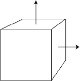
Compiling the Chapter05SampleBase class at this point will display the output shown in Figure 5-1. Moving the mouse cursor left and right will rotate the camera left and right, allowing you to view the three mesh objects in the scene from any angle. Because we have yet to set the material property on any of our meshes, they are all displayed using the default material type—a WireColorMaterial object with a random color defined for the surface fill. We will investigate this material type in more detail later in this chapter, but for now, let's kick off our first example with a look at some basic material types available in Away3D.
Color materials use simple color values to paint the visible elements of a 3D object. Various types of color material exist, differing in the way they apply color to an object and the way the object is rendered. By contrast, bitmap materials use an image to texture the surface of a 3D object as if it were covered in a piece of gift wrap. For bitmap materials to work, data points called UV coordinates must be available for each vertex of each face in the mesh. A UV data point is a 2D vector that represents the (x, y) position on the surface of the texture image to be mapped to the corresponding 3D (X, Y, Z) vertex position on the surface of a face. The material then uses bilinear interpolation to stretch the texture's pixel data between UV positions for each vertex in the face (which is typically a triangle or quadrilateral polygon). The entire process is known as texture mapping.
UV coordinates for imported models are usually created by the 3D artist in a modeling package prior to export, but we will take a closer look at how UV coordinates can be generated and modified from inside Away3D in Chapter 7 when we build our own custom 3D object from scratch.
To create our first materials example, let's start by extending the newly created Chapter05SampleBase class with the following document class, overriding the _createMaterials() and _toggle() methods with stubs ready for custom use:
package flash3dbook.ch05
{
  import away3d.core.utils.*;
  import away3d.materials.*;
  import flash.display.*;

  [SWF(width="800", height="600")]
  public class SimpleMaterials extends Chapter05SampleBase
  {
    [Embed(source="../../../assets/ch05/redapple.jpg")]
    private var AppleImage : Class;

    private var _bitmapMaterial : BitmapMaterial;
    private var _colorMaterial : ColorMaterial;

    public function SimpleMaterials()
    {
      super();

      _toggle();
    }

    protected override function _createMaterials() : void
    {
    }

    protected override function _toggle() : void
    {
    }
  }
}
The first defined global variable AppleImage is an embedded image asset, created from a file called redapple.jpg. Make sure the path reflects the actual location of the file on your hard drive. If you are working with the chapter download files from www.friendsofed.com, this path should be correct from the outset.
Note
The [Embed] meta-tag used in the preceding example compiles images and other file assets into project SWFs created with Flex Builder, Flash Develop, FDT, or any other editor that uses the Adobe Flex SDK to compile. This method of asset inclusion mimics the organization and compilation of library assets contained in an FLA. Since the introduction of CS4, [Embed] tags will compile in Flash Professional as well, but if you're using CS3, you will need to modify the code and update the library assets of the container FLA in the following way to compile: Import the image file into the library, open its properties panel, and check the Export for Actionscript option. Underneath, enter the name of the variable you find directly under the [Embed] tag line (in this case AppleImage) as the class name. Also, make sure you remove the [Embed] line and the one that directly follows it from the source code. The modification will allow this and any subsequent examples using the [Embed] meta-tag to work in CS3.
The remaining two private variables called _bitmapMaterial and _colorMaterial are global placeholders for the two material classes we will be testing: the BitmapMaterial and ColorMaterial classes.
To complete our example, we need to fill out the code required in our _createMaterials() and _toggle() method stubs. First, we need to create instances of our material classes by adding the following code to the _createMaterials() method:
_bitmapMaterial = new BitmapMaterial(Cast.bitmap(AppleImage));
_colorMaterial = new ColorMaterial(0xFFAA00);
For the BitmapMaterial instance, we see the first use of the Cast class. This handy Away3D utility resides in the away3d.core.utils package and contains static methods for converting one type of ActionScript object to another. In this case, the BitmapMaterial class requires a BitmapData object representing the texture to be passed in its constructor argument. However, an object created by an [Embed] meta-tag class will be of type Class. In previous chapters, we created an instance of the AppleImage class variable and directly cast it into a regular ActionScript Bitmap object, then extracted the bitmap data from its bitmapData property. However, this approach requires typing a couple of extra lines of code every time you needed a new bitmap material. With Cast, the work is done for you in a quick, neat fashion.
The ColorMaterial instance is passed a constructor argument that sets the color value of the material on instantiation. Color values are unsigned integers by type, and in this example, we define the color in hexadecimal as 0xffaa00, a bright orange. Hexadecimal is a common notation for color values as it is generally easier to read than the equivalent decimal value. ColorMaterial requires no constructor arguments by default but will end up using a random color if none is given. The color could also be set after instantiation by using the color property of the ColorMaterial object.
Next, we add the code required for toggling between our materials at runtime. The idea here is to be able to hot swap materials on all our objects, so that direct comparisons can be made. Remember that the base class sets up the _toggle() method to be invoked when we click with the mouse anywhere on the stage. By updating the _state class variable when this occurs, we will know what to do the next time the _toggle() method is called. For our SimpleMaterials example, we have two possible states to toggle between. Using the _state integer variable, we identify these as 0 and 1 in a simple switch statement by adding the following to the _toggle() method:
switch (_state) {
  case 0:
    _cube.material = _colorMaterial;
    _sphere.material = _colorMaterial;
    _ape.material = _colorMaterial;
    _state = 1;
    break;
  case 1:
    _cube.material = _bitmapMaterial;
    _sphere.material = _bitmapMaterial;
    _ape.material = _bitmapMaterial;
    _state = 0;
    break;
}
In the preceding code, we see that if the _state variable returns 0, the color material is applied to all mesh objects by resetting their material properties, and _state is reset to 1, ready for the next click. Likewise, if the _state variable returns 1, the bitmap material is applied to all mesh objects, and _state is reset to 0.
Compiling the example, our three mesh objects are rendered with our AppleImage texture applied using the bitmap material option. Moving the mouse left and right rotates the camera left and right around the origin of the scene. The bitmap material option is used initially because the _toggle) method is called once in the constructor of the SimpleMaterials class, setting up a default bitmap material state. Clicking once anywhere in the Flash movie swaps the bitmap material for the orange-colored material on all objects. This looks very flat by comparison—so much so that if the camera remains still by keeping the mouse in the center of the movie, you'd be hard pressed to tell you were looking at a 3D scene and not just three irregular orange shapes. Jumping back to the bitmap material option with a further click, we can really start to see the extra detail texture mapping adds when applied to a mesh object. A comparison of the two results is displayed in Figure 5-2.
Figure 5.2. The two states of the SimpleMaterials example side by side: ColorMaterial with orange faces on the left and BitmapMaterial with textured faces on the right
The advantage of using bitmap materials over color materials doesn't stop with detail enhancement. Textures can be created to simulate objects lit by a light source, providing a greater level of realism in a scene. However, this method of static shading (or texture baking as its more commonly known) can only go so far; for maximum realism Away3D can apply shading in real time, as you will see in the shading materials section later in this chapter.
Wire materials are so called because they provide a wireframe look to a 3D mesh object. In Away3D, all materials inherit from a basic wire material represented by the WireframeMaterial class found in the away3d.materials package including the default WireColorMaterial class, which is set to use a black color for its wire component. This material doesn't win any prizes for aesthetics but is useful for debugging purposes thanks to its ability to draw all the lines that connect the vertices in a face, as well as filling all faces with a solid color.
As an alternative look, the WireframeMaterial class can be used when we want to only draw the outlines of faces, without a solid fill. Let's extend our chapter base class to see how these two materials compare:
package flash3dbook.ch05
{
  import away3d.materials.*;

  [SWF(width="800", height="600")]
  public class WireMaterials extends Chapter05SampleBase
  {
    private var _wfMaterial : WireframeMaterial;
    private var _wcMaterial :  WireColorMaterial;

    public function WireMaterials() {
            super();
            _toggle();
    }

    protected override function _createMaterials() : void
    {
    }

    protected override function _toggle() : void
    {
    }
  }
}
In the preceding code, we define two private variable placeholders for an instance of WireframeMaterial and WireColorMaterial. The constructor calls the _toggle() method once to execute the code we eventually create for initializing our materials. We also override the _createMaterials() and _toggle() methods, ready for our custom functionality. Now, let's create our material instances by adding the following code to the _createMaterials() method:
_wfMaterial = new WireframeMaterial();
_wfMaterial.wireColor = 0x000000;

_wcMaterial = new WireColorMaterial();
_wcMaterial.color = 0XCCCCCC;
_wcMaterial.wireColor = 0x666666;
The first two lines of code create a WireframeMaterial object and set its wireColor property to black. This will produce a black line drawn around all triangles. The remaining code creates a WireColorMaterial specified by two properties, color for the face color and wireColor for the line color. Here we are using property setters for updating the color values of our materials, but in the same way you saw in the previous example for the ColorMaterial class, we can also set the color for each material in the class constructor, corresponding to wireColor for the WireframeMaterial class and color for the WireColorMaterial class.
Next, we fill out our script for switching between materials by adding the following lines of code to the _toggle method:
switch (_state) {
    case 0:
         _cube.material = _wfMaterial;
         _sphere.material = _wfMaterial;
         _ape.material = _wfMaterial;

         _cube.bothsides = true;
         _sphere.bothsides = true;
         _ape.bothsides = true;
         _state = 1;
         break;
    case 1:
         _cube.material = _wcMaterial;
         _sphere.material = _wcMaterial;
         _ape.material = _wcMaterial;

         _cube.bothsides = false;
         _sphere.bothsides = false;
         _ape.bothsides = false;
         _state = 0;
         break;
}
Once again, we start by checking the value of the _state variable and react accordingly by setting the material property of all mesh objects to the WireframeMaterial instance if _state returns 0, and the WireColorMaterial instance if _state returns 1. We also set reset the bothsides property of the mesh objects depending on the type of material being used - when wire materials are used we need to see both sides of the geometry and the bothsides property is reset to true, but when color materials are used we only see the front faces of the geometry and the bothsides property can be reset to false. In each case, _state is reset to the alternative state value, ready for the next mouse click.
Compile the code, and click the stage anywhere to toggle between the two materials. Figure 5-3 portrays the appearance of both states side by side. Each material is useful for debugging a mesh when you need to see the exact orientation of the faces, and the application of the WireframeMaterial instance has the added bonus of only drawing the triangle outlines, allowing both sides of the object to be displayed at once as long as the bothsides property of the mesh object is set to true. The stylized effect of a wire material can also be useful in certain design situations.
In the real world, light reflected from the surfaces of the objects around us enters our eyes and produces a perceived image of the scene. Without a light source, everything would appear black. Simulating this process in a computer is known as shading and typically requires a large amount of processing.
One method of shading calculates virtual light rays for every pixel in the view, in a technique known as ray tracing. This method is used by the majority of professional 3D modeling programs to render high-quality 3D images. However, real-time 3D engines require a fast render speed and consequently aim to approximate a lot of real-world processes rather than carrying out faithful simulations. Instead of measuring light intensities for every pixel in an image, values are estimated using a variety of techniques ranging from precalculating intensities in a texture (the previously mentioned texture baking technique) to texel-based normal mapping that uses an extra texture image to calculate light intensities across the surface of an entire object's texture in a single step. We will look at the latter technique in more detail later in this chapter.
In the majority of preceding chapter examples, we have gotten away with not using any shading techniques on our materials. This approach is perfectly acceptable when speed is a priority over image quality. But if we want to produce 3D scenes with a higher degree of realism, shading materials are one option we can use. When a shading material is applied to a face, the resulting rendered surface can be brighter or darker than the actual color, depending on the shading calculations. In simple terms, a surface that directly faces toward a light source will appear brighter, while one that directly faces away will appear darker. A shading material produces an overall intensity map of light to be applied to the underlying texture or color of the object, commonly referred to as the light map of the object.
In Away3D, several different types of shading material exist, offering varying degrees of detail and requiring varying amounts of processing. As is the case with much real-time 3D content, finding a happy balance between these two quantities is the main basis on which choices are made.
For a shading material to work, we need to define at least one light source. In Away3D, lighting is achieved by adding light source objects to a scene. Three types of light source objects can be used: point, directional, and ambient. These are represented by the classes PointLight3D, DirectionalLight3D, and AmbientLight3D found in the away3d.lights package, and each type of light source produces a different shading result when applied to a shading material.
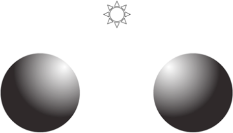
Point light sources work in a way similar to a single light bulb and are represented in Away3D by the PointLight3D object. They emit light in all directions from a definable position in the scene. If a point light is positioned between two objects, the objects will appear lit from opposite directions because the relative position of each object with regard to the light source is reversed. An illustration of this shown in Figure 5-4.
A defining characteristic of the point light source is the falloff over distance exhibited by the intensity. As in the real world, the overall intensity of reflected light from an object's surface is proportional to the inverse square of the distance from the surface to the light source. This means that the brightness of a light beam decays with the distance (d) from the light by an amount 1/d2. The overall brightness of a light source can be adjusted using the brightness property of the PointLight3D object, but the decay of intensity over distance will always follow the same curve.
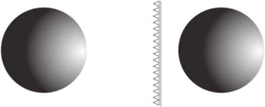
Directional light sources are represented in Away3D by the DirectionalLight3D class and can be imagined as light-emitting, infinitely large planes with all emitting rays pointing in the same direction. This is in contrast to point lights whose rays emit in all directions from a center point.
A directional light source is a simplification of the kind of light field generated by a point light source with near-infinite brightness positioned at a near-infinite distance. In this scenario, the natural falloff of the point light would be barely noticeable over the differing distances in our scene, and to use a point light object for such a setup would be impractical. All that is required to set up a directional light source is a 3D direction vector that defines the direction of the light rays. This is set on a DirectionalLight3D object using the direction property. For a shading material, the most important piece of information when dealing with a directional light is the angle between the light source direction and the object's surface. It is assumed that the intensity of the light is constant at all distances.
Figure 5-5 illustrates an example scenario, with a directional light source (drawn as a wall of parallel beams) emanating from the right-hand side of the screen. In Away3D, there is no such thing as a position for a directional light source; here, we are imagining one for illustrative purposes. Both the right and left spheres are lit identically, despite the left sphere being further away from the light source than the right sphere. This characteristic of directional lights makes them ideal for simulating sunlight in an outdoor scene, as well as being generally more efficient than their closely related point light counterparts, requiring fewer calculations to produce a similar shading effect.
Ambient light sources are represented in Away3D by the AmbientLight3D class and can be considered one of the simplest types of light source. Adding an ambient light source to a scene will light all faces of all meshes in the scene equally, regardless of angle or position.
In Away3D, ambient lights have an effect on only a few shading materials. They are commonly used together with the other light source types to boost the overall brightness in a scene. For those shading materials that do not react to ambient lights, directional lights and point lights have their own internal ambient coefficients to provide an ambient component to their lighting effect.
Creating a light source and preparing it for use with a shading material is as easy as instantiating the respective class, setting its color property, and adding it to the scene using the custom addLight method. This process is identical for all light types. For example, a red point light source would be created in the following manner:
var light : PointLight3D = new PointLight3D();
light.color = 0xFF0000;
myView.scene.addLight(light);
Each type of light brings its own configuration properties, the one common property being color, which sets the emitting color value for the light object. Ambient lights don't require any further configuration due to their simplicity, so we will take a closer look at the remaining two types of light source on offer.
The brightness property on the DirectionalLight3D and PointLight3D classes controls the overall intensity of the light that is emitted from the light source. For a directional light source, this means the overall intensity at any position in the scene. The effects of a light source on the surface of a shading material are cumulative, so an Away3D scene with more than one light object will have the resulting intensities added together (through color components) to calculate the total light intensity to be applied. A point light source's intensity is attenuated over distance, so in this case the brightness property represents the intensity of the light 500 units away from the source. The default brightness value is 1.0 for both PointLight3D and DirectionalLight3D.
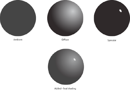
The basic principal of the rendering process for any shaded material is to calculate the intensity of the light entering the camera from any point on the surface of a face. If you investigate how different materials appear around you in the real world, you will quickly come to realize that they each react to light in subtly different ways. Some are reflective and glossy, while others are diffuse and dull. Real real-world materials have physical properties on a microscopic level that influence these different characteristics, but in a real-time 3D engine, replicating these surface perturbations in the same terms would be too complex. For most engines, the reflected light from the surface of a material is represented by three distinct components: ambient, diffuse, and specular reflections. These add up to a cumulative shading intensity called a light map, which is applied to the underlying shading material color to produce the final appearance of the material.
The ambient component of a light source is applied in a similar manner to the output of an AmbientLight3D object. It represents the fraction of light incident on the surface of a shading material that originates as ambient light from the light source. For example, a point light source inside a room has its ambient component created from diffuse reflection of the interior walls bouncing light back into the room. The resulting component is simulated by applying a uniform intensity to all shading materials encountered in a scene.
The diffuse component of a light source represents the fraction of incident light that originates directly from the source and is then scattered in all directions from the surface of a shading material. Its purpose is to simulate the light scattering performed by a soft material such as a ball of putty, that at a microscopic level is pitted and irregular, diffusing light uniformly regardless of incident angle. Because of its scattered nature, the diffuse component of a light source is ambivalent to viewing angle and is only concerned with the concentration of the beam incident on the surface of a shading material to calculate its reflected intensity. This is directly affected by the incident angle, which can be considered as the angle at which light from the light source arrives at the material surface.
The specular component of a light source represents the fraction of incident light direct from the source that is then reflected in a mirror-like fashion from the surface of a shading material. For this to occur, the incident angle of the light must be near equal the viewing angle of the camera, as is the case for a real mirror. For example, the reflected light seen in a mirror from someone holding a torch would be considered the specular component of that light source. As a comparison, if the same torch were shone on a stone wall, the reflected light seen would be the diffuse component of the light source.
Figure 5-6 illustrates how the resulting ambient, diffuse, and specular components of a light source are blended together to produce the light map for a sphere object with a shading material applied. The properties on point and directional lights that control the individual intensities of ambient, diffuse, and specular shading are unsurprisingly called ambient, diffuse, and specular. They represent the fraction of total light (taken from the brightness) to be used for that shading component, as a decimal number between 0 and 1. For example, the intensities seen in Figure 5-6 would be set using the following code snippet:
myPointLight.ambient = 0.3;
myPointLight.diffuse = 0.7;
myPointLight.specular = 1;
As previously mentioned, shading materials are specific material types in Away3D that react to light. In this section, we will take a tour through the most frequently used types, highlighting the strengths and weaknesses of each. It is worth reiterating that almost all shading materials are very processor intensive and need to be used sparingly in an Away3D project. Recent advances in the Flash 10 Player have allowed some optimizations to be performed on certain shading material classes, but if the frame rate of an application is to remain smooth, the amount of shading materials use will always need to be kept within limits set by the processing overheads.
One of the simplest and most efficient methods of shading a 3D mesh object is known as flat shading. This calculates a single reflected intensity for each face based on the angle of the face to the light source. The result is applied to the base color of the material, producing the final output. There are two classes that perform this type of shading: ShadingColorMaterial and WhiteShadingBitmapMaterial. Both of these material classes work similarly to their respective nonshading counterparts, without the use of any processor-intensive layering, and are therefore useful as fast shading options.
For simplicity, the WhiteShadingBitmapMaterial class assumes the light color to be white for all light sources. The ShadingColorMaterial class is more versatile in its coloring, reacting to different colored lights and allowing you to configure different material colors for the three components of the light source. For example, a ShadingColorMaterial can use a red hue for its ambient color, a blue hue for its diffuse color, and a green hue for its specular color. The disadvantage of using ShadingColorMaterial is its lack of texture mapping, meaning that any color settings are applied across the entire material surface.
Let's create a sample class where the two types of flat shading material can be compared, starting with the following document class definition extending the Chapter05SampleBase class:
package flash3dbook.ch05
{
  import away3d.lights.*;
  import away3d.core.math.*
  import away3d.core.utils.*
  import away3d.materials.*;

  import flash.text.TextField;

  public class FlatShadingMaterials extends Chapter05SampleBase
  {
    private var _tf : TextField;

    private var _pointLight : PointLight3D;
    private var _dirLight : DirectionalLight3D;

    [Embed(source="../../../assets/ch05/redapple.jpg")]
    private var AppleImage : Class;

    private var _bMaterial : WhiteShadingBitmapMaterial;
    private var _cMaterial : ShadingColorMaterial;
public function FlatShadingMaterials()
{
super();
_createLights();
addChild(_tf = new TextField());
_toggle();
}
protected function _createLights() : void
{
}
protected override function _createMaterials() : void
{
}
protected override function _toggle() : void
{
}
}
}In the preceding code, we start by declaring a text field variable that will give us an indication of state for the toggle functionality. We then define two private variables called _pointLight and _dirLight to be used as our comparative light sources. Next, we embed the same redapple.jpg image file used earlier in this chapter, and as usual, the file path should work fine if you are working with the downloaded sample files. Similarly, the remaining two private variables called _bMaterial and _cMaterial are global placeholders for the two materials we will be testing in this example.
Aside from the usual initializing call to the _toggle() method in the constructor, we create a new TextField object for our _tf variable and add it to the display list. We then call a new method specific to this example called _createLights(), which for now is defined further down as an empty stub. We finish with the usual _createMaterials() and _toggle method overrides, ready for some custom functionality.
To start with we will create two lights objects using an instance of the PointLight3D class and DirectionalLight3D class, in order to compare the relative effects of each. We begin configuring our point light source by adding the following lines of code to the _createLights() method:
_pointLight = new PointLight3D();
_pointLight.position = new Number3D(70, 200, −200);
_pointLight.ambient = 0.1;
_pointLight.diffuse = 0.5;
_pointLight.specular = 1;
_pointLight.brightness = 1;
Here, the position of the point light is set to be 200 units above the scene's origin and 70 units to the right, locating it over the top of the sphere primitive in our scene. The ambient, diffuse, and specular properties of the light source are then set to provide a decent lighting range across the shading calculations. These values often require a little tweaking to achieve the desired effect, but the numbers used here are usually a good starting point. The last property configured is brightness, set to ensure the overall light levels from the point light source are appropriate, given the falloff over distance exhibited with this type of source.
Next, we configure our directional light with the following code added to the _createLights() method:
_dirLight = new DirectionalLight3D();
_dirLight.direction = new Number3D(70, 200, −200);
_dirLight.ambient = 0.1;
_dirLight.diffuse = 0.5;
_dirLight.specular = 1;
_dirLight.brightness = 3;
Here, we set the direction vector of our DirectionalLight3D object to match the same vector created for the position of the point light relative to the center of the scene. All component properties of the light source are set to match the point light values as closely as possible, the only major difference being the brightness value, which takes into account the uniform nature of the directional light intensity. Brightness can be set to any number, but generally, the aim is to provide a sufficient intensity that doesn't wash out the resulting shading with nothing but white light.
Now, we set up our instances of ShadingColorMaterial and WhiteShadingBitmapMaterial on the material properties of the mesh objects by adding the following to the _createMaterials() method:
_bMaterial = new WhiteShadingBitmapMaterial(Cast.bitmap(AppleImage));

_cMaterial = new ShadingColorMaterial();
_cMaterial.ambient = 0xff0000;
_cMaterial.diffuse = 0x008800;
_cMaterial.specular = 0x0000ff;

_cube.material = _cMaterial;
_sphere.material = _cMaterial;
_ape.material = _bMaterial;
Looking at the first line in the preceding code, you can see that a WhiteShadingBitmapMaterial object is instantiated in a similar way a nonshading BitmapMaterial object, requiring a BitmapData object passed in its constructor argument that contains the texture to be used for the material. As shown earlier in the SimpleMaterials example, using the Cast class on our embedded AppleImage asset is a simple way to extract this data. Next, we instantiate a SimpleMaterials object and use the overriding component colors rather than the base color property to define its shading by setting the ambient, diffuse, and specular properties to a selection of color values. Finally, we apply our shading materials to the desired mesh objects, with the WhiteShadingBitmapMaterial instance applied to the MonkeyMesh model and the ShadingColorMaterial instance applied to the Cube and Sphere primitive objects.
To complete the FlatShadingMaterials example, we want to enable light source swapping at runtime using the same toggle system as before. We do this by adding the following code to the _toggle() method:
switch (_state) {
  case 0:
    _view.scene.addLight(_pointLight);
    _view.scene.removeLight(_dirLight);
    _tf.text = 'POINT';
    _state = 1;
    break;
  case 1:
    _view.scene.addLight(_dirLight);
    _view.scene.removeLight(_pointLight);
    _tf.text = 'DIR';
    _state = 2;
    break;
  case 2:
    _view.scene.removeLight(_dirLight);
    _view.scene.removeLight(_pointLight);
    _tf.text = 'NONE';
    _state = 0;
    break;
}
This adds and removes the relevant light source from the scene and updates our descriptive text of what is currently being used as a light source. Starting with the default value of the _state variable 0, PointLight3D is activated and our descriptive text is set to POINT. A single mouse click will advance the state to 1, activating our DirectionalLight3D object and setting the descriptive text to DIR. A second click will use no lights at all and set the descriptive text to NONE. A further mouse click will start the cycle again, returning us to the 0 state with PointLight3D active.
Compiling the example reveals the three mesh objects displayed with shading materials. The monkey model has the shading equivalent of a bitmap material applied, while the cube and sphere primitives have the shading equivalent of a color material applied, with the results looking similar to Figure 5-7. Because we have defined separate material colors for use by the ambient, diffuse, and specular components of the light source on the ShadingColorMaterial object, the shading color applied to the face elements of the cube and sphere primitives should clearly show what intensity from the source is attributed to each component. Faces pointing away from the light source will be colored red (the ambient component), whereas those directly reflecting the light source will be colored blue (the specular component). All other faces will appear green (the diffuse component) or some mixed shade of green, red, and blue where the component intensities combine. Of course, this explanation does not apply to the monkey model, because WhiteShadingBitmapMaterial can only shade in varying degrees of white. However, the monkey model does retain a texture to its surface, which is one advantage of using this type of shading material.
Figure 5.7. The POINT state of the FlatShadingMaterials example, rendered using simple shading materials. The cube and sphere primitives both use the ShadingColorMaterial object, while the monkey model has the WhiteShadingBitmapMaterial object applied.
Clicking once anywhere on the stage will swap the default PointLight3D object for the DirectionaLight3D object. With this light source active, you can see that intensities for reflected components of the light vary uniformly across all objects, demonstrating the uniform nature of the directional light source. Also, the angles of incidence for the incoming light on each object will match, creating matching areas of shadow (areas lit by the ambient component only) for each object. A final click will remove lights from the scene altogether, causing all mesh objects to be rendered black as you would expect in a real-world scenario.
Because we are generally restricted to relatively small numbers of faces in an Away3D scene, flat shading can be somewhat limiting. You only have to look at the sphere from our FlatShadingMaterials example to realize that the big square shading areas are somewhat revealing of our low polygon count. To achieve some smoother shading effects, we need to start looking at materials that generate light maps with a level of detail independent of polygon count.
Normal map shading (or DOT3 shading) is an approach to shading materials that can be used to work around the low polygon problems associated with real-time 3D. It is a little more expensive in processing terms than the simple shading techniques described in the previous section, but in certain scenarios, the visual benefits will vastly outweigh the increase in processing time.
The idea behind normal map shading is to process incident light intensities at a texel level rather than a face level. A texel is the representation of a single pixel of a bitmap texture as seen on the surface of an object with a texture mapping material applied. With separate light calculations made for each texel in a material, the detail of a mesh object's light map can be far greater than that achieved by single face calculations.
In normal map shading, we want to process the perceived light intensity of each texel of a material's texture. With flat shading, light intensity calculations are made by using a vector called the face normal that represents the 3D vector perpendicular to the surface of the face and determines the direction in which the face is pointing. In Figure 5-8, a simple cube is depicted showing two of its face normal vectors, on the top and right side. For normal map shading to work, we need the same normal vector information for each texel of the material texture, stored in an easily accessible data format. This takes the form of a second bitmap image created alongside the texture, known as a normal map.
A normal map is created programmatically in a process called normal mapping, which usually occurs at the model creation stage. We want the normal values in a normal map to vary in a much smoother way to the normals produced by face calculations, and there are two ways this can be done. The first is to start with a more detailed model that contains many more triangles and iterate through each texel of the material, generating a normal value based on a smoothed face normal value. The second is to use a height map (or bump map) texture to perturb the surface normals of the texels, again smoothing out the variation between face normal values but, in this case, producing a surface that has added relief detail. Typically, normal maps store normal information in color channels, with red, green and blue (RGB) values corresponding to the x, y, and z values of the normal vector. Once a normal map has been created, the amount of detail in an object's light map is no longer dependent on the polygon count of the model, and the geometry can be simplified to whatever is acceptable for the 3D engine to render. However, each normal map is tied to the object it was created for; consequently, each normal mapping material can only be applied to the object used in its creation.
Because a normal map stores values relating to the surface normal of a texel, each pixel in the normal map image must refer to a unique texel on the model surface. Unfortunately, many models are built with areas of a texture map that are reused for more than one area of a model's surface. For example, when texturing a car, the same piece of a texture can potentially be used for the left and right sides of the body. This results in a problem known as overlapping UVs, where a reversed-engineered map of a mesh's face's UV coordinates printed onto the texture creates overlapping polygons. A model that has no overlapping UVs is required for effective normal mapping.
Figure 5-9 depicts the normal map of a sphere (one that we will be using in our next code example). Normal maps produce quite colorful images because of the channel mapping that goes into their creation. To see the map in full color, look for the sphere_normals.jpg image inside the sample files for this chapter.
With a bit of effort, you can deduce some information about the geometry of the related object just from looking at a normal map. Remember that the X, Y, Z vector of the texel's normal is represented by the RGB value of the corresponding pixel. Along the top edge of Figure 5-9, all pixels are some shade of green, signifying that the texel normals are pointing up along the Y axis. If we consider that the texture of this material maps onto a sphere similarly to the way a map of the world maps onto a globe, the top edge of the texture will converge around the north pole of the sphere creating upwardly-pointing normals and confirming our green values. Using the same logic, we can deduce that the color shift from blue to magenta to red to light blue and back again across the central line of pixels in the normal map represents a horizontal texel normal vector rotating in a circle around the equator of the sphere.
The task of generating a normal map generally falls to the 3D designer or texture artist and for fairly good reasons; the best tools available to create normal maps are modeling and 3D rendering packages such as Blender, 3ds Max, Maya, and Cinema4D. For those without access to such software, there also exists a free Adobe AIR application called Prefab3D, downloadable from the Adobe AIR Marketplace at www.adobe.com. Developed by core Away3D developer Fabrice Closier to produce normal map images and more, this application works particularly well alongside Away3D in the preparation of 3D assets.
As you can imagine, the exact steps to render a normal map will differ from application to application, but here are a few pointers to help generate maps for use in Away3D:
The UV coordinates on a high-polygon mesh used to render a normal map needs to match that of the low-polygon mesh used in the engine.
Overlapping UVs will cause problems when rendering the resulting light maps for the object.
Always use the object's local coordinate space (commonly referred to as object space) for the normal vector values in a normal map.
Make sure your mesh object's geometry is oriented the same way in your modeler as it appears in Away3D. If the local axes don't align, rotate your model to match them up before generating the normal map.
The expected mapping of color channels to normal vector coordinates in Away3D is RGB to XYZ (red is X, green is Y, and blue is Z).
Once your normal maps have been created, they can be imported into Away3D as JPG or PNG images and used with any DOT3 material to produce nrmal map shading.
Materials in Away3D that use normal mapping in some way have a prefix of Dot3 in their class name. Let's extend the Chapter05SampleBase class to create an example using normal map shading on all our objects.
package flash3dbook.ch05
{
  import away3d.core.math.*;
  import away3d.core.utils.*;
  import away3d.lights.*;
  import away3d.materials.*;
  import away3d.primitives.*;

  import flash.display.*;
  import flash.events.*;

  [SWF(width="800", height="600")]
  public class UsingNormalMaps extends Chapter05SampleBase
  {
    private var _dirLight : DirectionalLight3D;

    [Embed(source="../../../assets/ch05/sphere_normals.jpg")]
    private var SphereNormals : Class;

    [Embed(source="../../../assets/ch05/ape_normals.jpg")]
    private var ApeNormals : Class;

    [Embed(source="../../../assets/ch05/cube_normals.jpg")]
    private var CubeNormals : Class;

    [Embed(source="../../../assets/ch05/redapple.jpg")]
    private var AppleImage : Class;

    private var _angle : Number = 0;

    public static const RADS_PER_DEG : Number = Math.PI / 180;
public function UsingNormalMaps()
{
super();
_cube.mappingType = CubeMappingType.MAP6;
_createLights();
}
protected function _createLights() : void
{
}
protected override function _createMaterials() : void
{
}
}
}We start by embedding three pregenerated normal map images, one for each mesh object. The ape_normal.jpg and sphere_normal.jpg images are generated by smoothing face normals of the existing geometry, while the cube_normal.jpg has been created with an additional height map to add a bit of extra detail to the cube's surface, as you will see. Our next embedded image, the redapple.jpg shown in previous examples, will be used for our base material texture on each object. All images can be found in the chapter files from the Downloads section of www.friendsofed.com. We finish our property definitions with a constant RADS_PER_DEG and a global variable _angle that will be used for rotation effects later in the class.
The constructor in the preceding code modifies the mappingType property of the cube primitive to MAP6, a special texture-mapping mode that is a requirement for the cube_normal.jpg texture, because it uses a different area of the texture for mapping each side of the cube. We then call _createLights(), a new method included in the class to setup the lights in a similar manner to the previous FlatShadingMaterials example. Finally, we override the _createMaterials() method, ready for our custom code. Before we define our materials, let's create our light sources by adding the following code to the _createLights() method:
_dirLight = new DirectionalLight3D();
_dirLight.direction = new Number3D(70, 500, −70);
_dirLight.ambient = 0.1;
_dirLight.diffuse = 0.5;
_dirLight.specular = 1;
_dirLight.brightness = 2;
_view.scene.addLight(_dirLight);
This creates a directional light source identical to the one in the FlatShadingMaterials example, so that a direct comparison can be made.
Note
Note that DOT3 materials react to point light sources in the current Flash 10 version of Away3D but not in the Flash 9 version. In the interest of maintaining maximum compatibility, we will only be looking at the directional light implementation in our example.
Now, we need to create the three BitmapData objects used for each of our mesh object normal maps and the one BitmapData object used for all base textures. Once again, this is easily done using the Cast class by adding the following code to the _createMaterials() method:
var texture : BitmapData = Cast.bitmap(AppleImage);
var sphereMap : BitmapData = Cast.bitmap(SphereNormals);
var apeMap : BitmapData = Cast.bitmap(ApeNormals);
var cubeMap : BitmapData = Cast.bitmap(CubeNormals);
With these in place, we can start creating the DOT3 materials. We use the Dot3BitmapMaterial class located in the away3d.materials package, adding the following code to the _createMaterials() method:
var sphereMaterial : Dot3BitmapMaterial;
sphereMaterial = new Dot3BitmapMaterial(texture, sphereMap);
sphereMaterial.specular = 0xFFFFFF;

var apeMaterial : Dot3BitmapMaterial;
apeMaterial = new Dot3BitmapMaterial(texture, apeMap);
apeMaterial.specular = 0xFFFFFF;

var cubeMaterial : Dot3BitmapMaterial;
cubeMaterial = new Dot3BitmapMaterial(texture, cubeMap);
cubeMaterial.specular = 0xFF0000;
The Dot3BitmapMaterial object requires two arguments in its constructor: the first for the bitmap data of the texture map (the same data used in a standard BitmapMaterial) and the second for the bitmap data of the normal map. Notice that in the preceding code, we set a specular property on the Dot3BitmapMaterial objects after instantiation. This is interpreted in a similar way to the specular property seen earlier on the ShadingColorMaterial object, defining the color of the reflected specular component of the light source. In the cases of sphereMaterial and apeMaterial, the specular property is set to white, but for cubeMaterial, it is set to red.
Now, we just need to apply these materials to their respective mesh objects by adding the following code to the _createMaterials() method:
_cube.material = cubeMaterial;
_cube.ownCanvas = true;
_sphere.material = sphereMaterial;
_sphere.ownCanvas = true;
_ape.material = apeMaterial;
_ape.ownCanvas = true;
While setting the material properties of each object, we also isolate each material to a unique rendering sprite for each object, known as a canvas. Because many shading materials are layered, isolating the objects that use them to their own canvas helps with the speed and consistency of the rendering process. This setup is easily configured by setting the ownCanvas property of each mesh object to true.
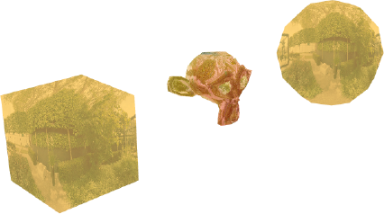
Compiling the code at this point will display something similar to Figure 5-10. On the sphere and monkey model objects, the shading appears smooth without a hint of the underlying polygons making up the mesh. The normal map on the cube illustrates how normal mapping can be used to add surface detail to an otherwise flat object—the apparent indentations on each side make it look like a die, despite the fact that no geometry has been added to the cube primitive.
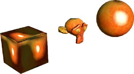
Figure 5.10. Normal map shading applied to our test objects, using externally created normal map images in the UsingNormalMaps example
As a final touch to the UsingNormalMaps example, let's override the _onEnterFrame() method to create a moving light source. Add the following code to the bottom of the class:
override protected function _onEnterFrame(ev : Event) : void
{
  _angle = (_angle + 5) % 360;

  var x : Number= 100 * Math.cos(RADS_PER_DEG * _angle);
  var y : Number = 50;
  var z : Number= 100 * Math.sin(RADS_PER_DEG * _angle);

  _dirLight.direction = new Number3D(-x, -y, -z);

  super._onEnterFrame(ev);
}
Here, we use our global _angle variable to increment a rotation value of 5 degrees every frame and then apply it to the direction vector of our directional light source with the help of some trigonometry. We calculate the x, y, and z components required for the direction vector of the directional light and then apply them in a new Number3D object. To ensure the rest of the example functions normally, we finish our modifications by calling the superclass _onEnterFrame() method. Recompiling the example rotates the directional light object around the scene with the light maps of the DOT3 materials updating in real time.
When considering highly reflective materials, the standard shading options you have seen so far are a little lacking in detail. What if you want an object to appear made of glass or chrome? The answer lies in a technique known as environment shading. This uses a cached image of the surroundings as the basis for a light map, overlaying a calculated reflection of the image onto an underlying color or texture.
Environment shading employs a technique called environment mapping to draw its light map. Let's create an example to demonstrate the effect by implementing the EnviroBitmapMaterial and EnviroColorMateiral classes in Away3D. Once again, we begin by extending the Chapter05SampleBase class with the following code:
package flash3dbook.ch05
{
  import away3d.core.utils.*;
  import away3d.materials.*;

  import flash.display.*;
  [SWF(width="800", height="600")]
  public class EnvironmentMaterials extends Chapter05SampleBase
  {
    [Embed(source="../../../assets/ch05/environment.jpg")]
    private var EnviroMap : Class;

    [Embed(source="../../../assets/ch05/redapple.jpg")]
    private var AppleImage : Class;

    private var _colorMaterial : EnviroColorMaterial;
    private var _bitmapMaterial : EnviroBitmapMaterial;

    public function EnvironmentMaterials()
    {
      super();

      _toggle();
    }

    protected override function _createMaterials() : void
    {
    }

    protected override function _toggle() : void
    {
    }
  }
}
As usual, we start our class definition by embedding the textures used in the example. You are familiar enough with the redapple.jpg texture by now, but the following environment.jpg file is a new image to be used as our environment mapping texture. Opening it up, you will see an image of a garden that has been morphed as though viewed through a fish-eye lens. Panoramic projections such as this work well with environment mapping materials and can be easily generated with the right image editing software. However, perfectly acceptable results can be achieved using a regular image of the scene you wish to see reflected in the surface of the material.
The next global variables we declare are two placeholders for the environment mapping material objects. The EnviroColorMaterial object applies an environment map to a standard color material, while the EnviroBitmapMaterial object does the same to a bitmap material. The constructor in the preceding code contains an initializing call to the _toggle() method, and the class is rounded off with the usual _createMaterial() and _toggle() stub methods.
To complete the example, we first need to fill out the _createMaterials method with the following code:
var texture : BitmapData = Cast.bitmap(AppleImage);
var envMap : BitmapData = Cast.bitmap(EnviroMap);

_colorMaterial = new EnviroColorMaterial(0xffcc66, envMap);
_bitmapMaterial = new EnviroBitmapMaterial(texture, envMap);

_cube.material = _colorMaterial;
_sphere.material = _colorMaterial;
_ape.material = _bitmapMaterial;
Here, we start with the familiar extraction of embedded image bitmap data using the Cast class and then use the result to define our environment materials. The EnviroColorMaterial takes a color value as its first constructor argument, while the EnviroBitmapMaterial takes the bitmap data for the material texture. They both expect an environment image as their second constructor parameter, which will be blended with the base texture or color of the material. We finish by applying the EnviroColorMaterial object to the cube and sphere primitives, and the EnviroBitmapMaterial object to the monkey model.
Compiling the example will display the output shown in Figure 5-11. As you rotate the view with the mouse, you'll see that both materials appear to be reflecting an invisible background environment.
In Away3D, environment materials use a reflectiveness property to control the degree to which an environment texture is reflected in the material's surface. This is represented by a fractional value between 0 and 1, with the default set to 0.5 (what you have seen so far). To compare different settings, add the following lines of code to the _toggle() method:
switch (_state) {
  case 0:
      _colorMaterial.reflectiveness = 0.1;
      _bitmapMaterial.reflectiveness = 0.1;
    _state = 1;
    break;
  case 1:
      _colorMaterial.reflectiveness = 0.9;
      _bitmapMaterial.reflectiveness = 0.9;
    _state = 0;
    break;
}
Recompile the EnvironmentMaterials example, and click the mouse anywhere inside the stage to see the reflectiveness property swap between 0.1 and 0.9 for both color and bitmap environment materials. Figure 5-12 shows the appearance of each setting side by side. Environment shading is one of the most efficient rendering shading techniques in Away3D, which make it a very versatile material option.
An animated material extends the functionality of a standard bitmap material to allow the contents of the texture image to be animated in real time. Using the MovieMaterial class in Away3D, it is possible to project time-line–based animations contained in a MovieClip or code-based animations contained in a Sprite onto the surface of a 3D mesh object. As the examples in this section will demonstrate, animated materials can also be made interactive through the surface of a 3D mesh object by setting the interactive property of a MovieMaterial object to true.
The MovieMaterial class is found in the usual away3d.materials package. Let's explore the functionality available by extending the Chapter05SampleBase class with the following document class:
package flash3dbook.ch05
{
  import away3d.primitives.*;
  import away3d.materials.*;
  import away3d.events.*;

  [SWF(width="800", height="600")]
  public class UsingAnimatedMaterials extends Chapter05SampleBase
  {
    [Embed(source="../../../assets/ch05/animatedTexture.swf")]
    private var AnimatedTexture : Class;

    [Embed(source="../../../assets/ch05/interactiveTexture.swf")]
    private var InteractiveTexture : Class;

    private var _movieMat :MovieMaterial;

    public function  UsingAnimatedMaterials()
    {
      super();
    }

    protected override function _createScene():void
    {
    }

    protected override function _createMaterials() : void
    {
    }
  }
}
In the preceding code, we embed two SWF files as global properties AnimatedTexture and InteractiveTexture. These will be cast to Sprite on instantiation for use in our MovieMaterial object. In this case, we override the _createScene() method, because we want to reconfigure our scene to display a single _cube primitive. We finish the class definition by overriding the _createMaterials() method with the usual method stub.
Now, let's create our single cube object by adding the following code to the _createScene() method:
_cube = new Cube();
_cube.width = 75;
_cube.height = 75;
_cube.depth = 75;
_view.scene.addChild(_cube);
This creates a cube with a size in all dimensions of 75 units and adds it to the scene. To complete the example, we need to apply a MovieMaterial object to the surface of the cube by adding the following code to the _createMaterials() method.
_movieMat = new MovieMaterial(new AnimatedTexture());
_cube.material = _movieMat;
Here, we use an instance of the AnimatedTexture class containing the embedded SWF file animatedTexture.swf for the required movie clip instance, passed in the constructor of the MovieMaterial object. Both embedded SWF files used here can be found in this chapter's resource download available at www.friendsofed.com. The animatedTexture.swf file contains a simple looping animated movie that can be previewed by opening the file using the stand-alone Flash Player. Compiling the code will display a single cube primitive with the animating movie clip projected onto every side. Notice that the default mapping used for this cube's UV coordinates projects an identical image of the texture onto each side of the cube, unlike the mapping used in the previous UsingNormalMaps example.
We can adapt the UsingAnimatedMaterials example to display an interactive movie material by replacing the preceding code for the _createMaterials() method with the following:
_movieMat = new MovieMaterial(new InteractiveTexture());
_movieMat.interactive = true;
_movieMat.smooth = true;
_cube.material = _movieMat;
Here, we pass an instance of the InteractiveTexture class in the constructor argument of the MovieMaterial object. Opening the associated inteactiveTexture.swf file in the stand-alone Flash Player will display a collection of Flash Professional UI components. These are ideal for use in an interactive texture demonstration, because they react to mouse events such as rollovers and clicks. To enable interactivity, we set the interactive property of the MovieMaterial object in the preceding code to true. A property called smooth is also set to true to produce an antialiased result for the texture mapping on the surface of the cube object. This helps when dealing with interface components in a texture, as items such as text and buttons appear clearer when antialiased.
Recompiling the example displays a cube similar to the one shown in Figure 5-13. Each side has the contents of the inteactiveTexture.swf file projected onto its surface, and using the mouse, you will quickly discover that interactivity is preserved.
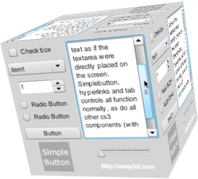
Figure 5.13. Interactive UI components mapped onto the surface of a cube using the MovieMaterial object
At times you might want to use MovieMaterial for movie clips that are not constantly animating. When the movie clip is static, redrawing the material is a waste of resources. To prevent a MovieMaterial from automatically redrawing, set its autoUpdate property to false. Setting it to true will resume updating every time the view is rendered. If at any point you need to refresh a MovieMaterial, without activating automatic redrawing, you can invoke its update() method.
The VideoMaterial class is an animated material that extends the functionality of the MovieMaterial class to accept FLV files as its animating source. The playback of Flash video inside a VideoMaterial object is achieved through transport control methods on the object that mirror the standard video component controls in Flash. In its simplest form, a VideoMaterial implementation is set up by creating a class instance and setting its file property to the location of an FLV file. We can try this out by replacing the contents of the _createMaterials() method in the previous UsingAnimatedMaterials example with the following code:
var videoMat : VideoMaterial = new VideoMaterial();
videoMat.file = '../assets/ch05/Away3D_Showreel2010.flv'
_cube.material = videoMat;
Here, we are setting the file property of the VideoMaterial object to a string value representing the path to our FLV file, which once again can be obtained through the resource download available at www.friendsofed.com. Recompiling the example will display the chosen video file playing back on the surface of the cube primitive. You can experiment further by using the play() and pause() methods of the VideoMaterial object to start and stop playback and the seek() method to jump back and forth in the video stream, as you would with a native flash.net.NetStream object.
In this chapter, we have covered the majority of material types that are available in Away3D. An important concept to take with you is that all materials are applied to 3D objects in the same way. However, a light source object in the scene is an extra requirement of a shading material if it is to function correctly.
With more complex material types such as those concerned with shading, the required real-time computations can be very processor heavy. Where possible, it is best to try to avoid using a lot of light sources and shading materials at the same time; often, it is possible to fake shading using the texture baking technique that requires no real-time processing overhead. It is also possible to optimize the use of animated materials with the use of the autoUpdate property. In Chapter 10, we will look further at some of the ways we can optimize the usage of materials.
Here is the summary of topics covered in this chapter:
Materials are created by instantiating classes from the
away3d.materialspackage. They are applied by setting thematerialproperty on a 3D mesh object or 3D element that supports them.Shading can be achieved in Away3D by adding at least one instance of a light source class from the
away3d.lightspackage to the scene and applying a shading material to any 3D mesh object in the scene to produce shading results.The
PointLight3Dclass creates a light source that emits light in all directions.The
DirectionalLight3Dclass creates a light source that emits light in a single direction from a near-infinite distance.The
AmbientLight3Dclass creates an ambient light source that raises the overall lighting level in a scene.
Visual results from shading materials are controlled from properties set on the light source (such as
ambient,diffuse, andspecularproperties) as well as on the material object (such as thecolorproperty on aShadingColorMaterialobject).Normal maps are images that define the normal vectors of each texel on the surface of the 3D mesh object and can be used to separate light map detail from mesh detail.
Normal maps are usually created in a 3D modeling application such as Blender or 3ds Max.
Normal maps are implemented in Away3D using DOT3 materials.
In Flash 9, normal maps are restricted to working with directional light sources only.
The mouse can interact with the contents of a movie clip texture through the surface of a 3D mesh using a
MovieMaterialobject with itsinteractiveproperty set totrue.Materials can be animated by using a
MovieMaterialobject with an animated movie clip, or byusing aVideoMaterialobject with an FLV video file.
In the next chapter, we will explore how the use of 3D vector shapes in Away3D can completely transform the way you import SWF files and text into your 3D projects, as well as the visual benefits of using curves instead of lines in a scene.