
In the majority of Away3D projects, the contents of a scene can be split into three categories. Primitives are simple 3D geometric shapes (such as the Cube primitive shown in the previous chapter) generated internally by the engine from preset collections of properties. Models derive their geometry from imported 3D file formats such as .dae, .3ds, or .obj files that are created using 3D modeling software. Sprites in 3D are flat images that scale with distance but ignore rotation, as if they are constantly facing the camera.
You obviously don't need to know everything about the different content types to produce high-quality 3D content, but knowledge of what's possible is a great catalyst for creativity! A practical example can be found at the end of this chapter; it demonstrates how the topics covered here can be used together for maximum effect in a single project.
The term "primitive" is a word commonly used in 3D graphics. In the majority of cases, including Away3D, it describes a simple three-dimensional geometric model such as a cube, sphere, or cylinder. The term is also used at times to speak of the most elementary visual part of a 3D object, such as a face or line segment, but in Away3D, we refer to these as "elements". Elements are visual surfaces or lines defined in 3D and have a form determined by the most fundamental of all 3D data, vertices.
A vertex is a single point in space represented by an X, Y, Z vector that serves as the building block of a larger shape. It is an invisible entity by itself, but visual elements are constructed using several vertices grouped together. For example, two vertices define a line; three vertices define a triangle, and so on. When defining a surface in 3D, a triangle is the simplest (and most common) representation, although any number of vertices above this is allowed. In Away3D, lines and surfaces are represented by the classes Segment and Face respectively, while vertices are represented by the Vertex class. All are found in the away3d.core.base package.
Faces and segments are the two most common visual elements in Away3D. In other 3D applications, a surface that consists of more than three vertices will sometimes be referred to as a polygon, whereas a three-vertex surface will be called a triangle. These are valid terms, but they don't appear very often in Away3D. Face is the generic name used for a surface, and segment is the generic name used for a line. Each can be made up of any number of vertices and can, therefore, have any number of straight edges.
Where faces and segments differ is in their permitted drawing routines. Faces will be drawn as filled areas; segments will be drawn as connecting lines. This aspect is explored in more detail in Chapter 5.
A mesh is a collection of vertices made visible by a collection of elements that use those vertices. As a saving measure, vertices can be reused by multiple elements in a mesh; it is rarely necessary to build elements with unique vertex points. A simple cube, for example, can have its shape defined by eight vertices, positioned at each corner. To create a solid object, these vertices are shared between twelve faces; six sides composed of two triangles each.
The cube belongs to a group of 3D objects called primitives. These are mesh-generating pieces of code that use simple geometric equations to produce their geometry. In Away3D, primitive objects are created using the classes found in the away3d.primitives package. Each primitive class controls the process of mesh generation via a series of properties that update the internal mesh configuration when changed.
A billboard is a 2D element that can be positioned inside a 3D space. It contains no rotational information, so when rendered it appears to face the camera as a flat image that scales with distance. Consequently, it only requires one vertex point representing its position in the scene. Billboards belong to the family of 3D objects commonly referred to as sprites, although there are some fundamental differences between these and the sprites we are accustomed to in Flash. The basic type can be created with the Sprite3D class located in the away3d.sprites package.
3D sprites were heavily used in the early years of 3D gaming, because they can easily depict a complex shape without the need for excessive drawing operations. Many different types exist—billboards being the simplest form that can replace objects with spherical symmetry (i.e., objects that look roughly the same from all angles), such as particles, spheres, and clouds. More complex sprites allow different images to be used for different viewing angles (a technique seen in old-school first-person shooter games for drawing the enemies) or permit some rotation to represent objects with axial symmetry (objects that look roughly the same from a restricted set of angles) such as barrels or trees.
As preparation for the following code samples, let's set up the base class that we will extend to create the sample projects throughout this chapter. The Chapter04SampleBase class is created in the flash3dbook.ch04 package and is written as follows:
package flash3dbook.ch04
{
  import away3d.cameras.*;
  import away3d.containers.*;

  import flash.display.*;
  import flash.events.*;

  public class Chapter04SampleBase extends Sprite
  {
    protected var _camera : HoverCamera3D;
    protected var _view : View3D;

    public function Chapter04SampleBase()
    {
      super();

      _createView();
      _createScene();
    }

    protected function _createView() : void
    {
      _camera = new HoverCamera3D();
      _camera.distance = 1000;
      _camera.tiltAngle = 10;
      _camera.panAngle = 180;

      _view = new View3D();
      _view.x = 400;
      _view.y = 300;
      _view.camera = _camera;
      addChild(_view);
      addEventListener(Event.ENTER_FRAME, _onEnterFrame);
    }

    protected function _createScene() : void
    {
      // To be overridden
    }

    protected function _onEnterFrame(ev : Event) : void
    {
      _camera.panAngle += (stage.mouseX - stage.stageWidth/2) / 100;
      _camera.hover();

      _view.render();
} } }
We start by importing the packages we will be using and then define the new class extending from Sprite (as is required with any document class). In the constructor, we call two methods: _createView() which sets up our basic view framework and the _onEnterFrame() handler method for rendering updates, and _createScene() which is where 3D content will be created and added to the scene. This is left blank in the Chapter04SampleBase class, to be overridden by our subsequent example classes.
Some primitives are more commonly used than others. Countless sphere models of the earth are sprinkled across the Web as part of a variety of projects. Planes are probably used in even more places, serving as image cards in product carousels and pages in sites with creative 3D navigation. These objects are all easy to create using Away3D.
For our first look at primitives, we create a document class extending Chapter04SampleBase:
package flash3dbook.ch04
{
import away3d.materials.*;
import away3d.primitives.*;
import flash3dbook.ch04.*;
[SWF(width="800", height="600")]
public class CommonPrimitives extends Chapter04SampleBase
{
public function CommonPrimitives()
{
super();
}
protected override function _createScene() : void
{
// Create default material
var mat : WireColorMaterial = new WireColorMaterial(0xcccccc);
}
  }
}The preceding code sets up our SWF with a width of 800 and height of 600, overrides the _createScene() method to allow us to add our custom content, and creates a new WireColorMaterial object that we will apply as our default material to our newly created Away3D primitive objects.
The plane primitive provides a natural step from two to three dimensions, thanks to its flat appearance. Its geometry consists of a 2D mesh in the shape of a square or rectangle. Because of this, planes are frequently used as a way of adding subtle 3D effects to an interface by projecting 2D content (such as images or text) onto the plane's surface as a material. The content can then be rotated in three dimensions, enabling some creative methods of display and interaction. This form of interface is commonly referred to as postcards in space, because the planes appear like individual postcards onto which 2D content is drawn.
Plane primitives are created using the Plane class from the away3d.primitives package. The yUp property defines whether the plane has its geometry built with its normal (the vector perpendicular to the plane's surface) pointing along the Y axis (true) or Z axis (false). The majority of Away3D primitives contain a yUp property in order to make this distinction. We can see the effect it has on a Plane object by adding the following lines to the _createScene() method.
var plane : Plane = new Plane();
plane.yUp = false;
plane.material = mat;
_view.scene.addChild(plane);
Here, we create a new plane primitive by instantiating a Plane object, configure its yUp and material properties, and add it to the scene. Notice that the plane's material property is set to the material instance we defined earlier. Try not to worry about what this is doing for now, as Chapter 5 will handle materials in more depth.
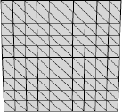
Compiling the CommonPrimitives example at this point will draw a front-facing plane with a grey outlined material. The plane's mesh is made up of two triangles by default. In some scenarios, you will want to subdivide the mesh into smaller triangles, for example, if you plan to deform the plane like a piece of paper. This type of subdivision, or segmentation, is achieved by using the segmentsW and segmentsH properties to subdivide along the width and height of the plane respectively. We can see the effects of subdivision by adding the following lines of code to the end of our _createScene() method from the previous sample:
plane.segmentsW = 10;
plane.segmentsH = 10;
Recompiling the CommonPrimitives example will display the result shown in Figure 4-1.
The size of a plane is determined by the width and height properties of the Plane object. These are both set to 100 by default but can be updated in a similar manner to the segmentsW and segmentsH properties by adding the following lines of code to the end of our _createScene() method.
plane.width = 200;
plane.height = 200;
Recompiling the CommonPrimitives example will display the same plane shown in Figure 4-1, only this time at twice the width and height.
Pause for a moment, run the code again, and roll over the Flash movie with your mouse to rotate the camera so that the plane is observed from behind. At this angle the plane turns invisible, because of an optimization technique known as back-face culling. Any face pointing away from the camera is ignored by default in the render process. The direction in which a face points is defined by a 3D vector known as the normal vector, which can be obtained in Away3D by using the getter property normal on the Face object. The normal vector is calculated as a vector perpendicular to the surface of the face. The direction the normal vector points is calculated such that if we were to observe the face by looking along its normal vector (so that it is pointing away from us), the vertices making up the face would be arranged in a counterclockwise order. It follows that if back-face culling is enabled on an object's mesh, a triangle prepared for drawing to screen with a clockwise ordering of its vertices will be omitted from the render process.
Back-face culling is usually a good thing, because most mesh objects (such as cubes and spheres) are built in such a manner that no faces are visible from their reverse side while viewing from outside the object. For example, you can't see the inside of a 3D box created by a cube primitive unless the camera is positioned inside the cube's mesh.
Planes are an exception to this rule, so you'll often want to turn off back-face culling for your plane objects. You can do this by setting the property bothsides to true.
plane.bothsides = true;
Add the preceding line of code to the end of our _createScene() method and recompile CommonPrimitives to see both sides of the plane when you rotate it with the mouse.
The cube is another commonly used primitive and is created in Away3D using the Cube class found in the away3d.primitives package. To continue our CommonPrimitives example, add the following code to the end of the _createScene() method to create a cube and position it 200 units to the right:
var cube : Cube = new Cube();
cube.material = mat;
cube.x = 200;
_view.scene.addChild(cube);
To make room for the cube, add the following line of code to position the plane 200 units to the left:
plane.x = −200;
Recompiling the CommonPrimitives example displays the cube and plane primitives side by side. The cube uses similar properties as the plane for defining segmentation and size, adding a depth and segmentsD property for the extra depth dimension of the cube. Adding the following code to the end of the _createScene() method will subdivide the cube object and double its width, height, and depth dimensions:
cube.segmentsW = 10;
cube.segmentsH = 10;
cube.segmentsD = 10;
cube.width = 200;
cube.height = 200;
cube.depth = 200;
Sphere primitives are created in Away3D using the Sphere class, again found in the away3d.primitives package. The size of a sphere is not determined by any width, height or depth properties we have seen in previous primitives, but by a single property called radius. To demonstrate this, add the following lines of code to the _createScene() method.
var sphere : Sphere = new Sphere();
sphere.radius = 50;
sphere.material = mat;
_view.scene.addChild(sphere);
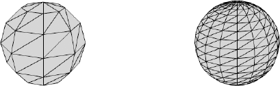
Recompiling the CommonPrimitives example will display the sphere in between the existing cube and plane objects. The sphere on the left in Figure 4-2 displays the rendered output. Here, we can instantly spot a problem with the sphere primitive, in that the small amount of faces making up the geometry causes it to look very blocky. To create a smoother looking sphere we need to use more faces. Luckily, this is possible by setting segmentation in the same way as the previous primitives, using segmentsW and segmentsH properties on the sphere primitive. Add the following lines of code to the _createScene() method.
sphere.segmentsW = 24;
sphere.segmentsH = 12;
Recompiling the CommonPrimitives example will display a sphere similar to the one on the right in Figure 4-2. In the preceding code, the values used for the segmentsW and segmentsH properties are not equal, as they were for the cube and plane primitives. This is because the construction for the sphere's geometry is different, with the overall distance between the first and last height segments half that of the distance between the first and last width segments (the latter of which would more commonly be referred to as the circumference). Taking this into account, the optimal configuration for an even segmentation of a sphere is to set half the amount of width segments compared to the amount of height segments.
Note
It might be tempting to raise the segmentsW and segmentsH properties of the sphere to a very high number to achieve a perfectly smooth surface. However, this approach has a large effect on the amount of faces rendered each frame and thus impacts heavily on performance. There are other ways of making surfaces look smooth, as we will see when covering materials in chapter 5.
So far, you have seen how to create solid objects composed of face elements in Away3D. But suppose we wanted to create a wireframe representation of a primitive, consisting of line segments forming the edges of a cube or edges of a plane? We have the ability to draw lines for the edges of faces as seen in the preceding example using the sphere primitive, but this is not ideal if the edges of our faces form polygons with more that three sides. We need a new way of constructing primitives in Away3D using segment elements. Happily, this can be accomplished using the wire primitive classes located in the same away3d.primitives package.
For our first look at wire primitives, we create a new document class extending Chapter04SampleBase.
package flash3dbook.ch04
{
  import away3d.materials.*;
  import away3d.primitives.*;

  import flash3dbook.ch04.*;

  [SWF(width="800", height="600")]
  public class CommonWirePrimitives extends Chapter04SampleBase
  {
    public function CommonWirePrimitives()
    {
      super();
    }
protected override function _createScene() : void
{
// Create default material
var mat : WireframeMaterial = new WireframeMaterial(0x000000);
}
}
}In the preceding code, the default material is set as a WireFrameMaterial object, a material that extends the base class SegmentMaterial and is therefore compatible with segment-based objects.
Most of our face-based primitives have equivalent segment-based primitives in the wireframe family. In Away3D, these wireframe primitives are created with classes named the same as regular primitives, but prefixed with the word "Wire". The following code is a reconstruction of the code added to the _createScene() method of the CommonPrimitives example in the previous section, with wireframe primitives in place of regular primitives:
var plane : WirePlane = new WirePlane();
plane.yUp = false;
plane.x = −200;
plane.width = 200;
plane.height = 200;
plane.material = mat;
_view.scene.addChild(plane);

var cube : WireCube = new WireCube();
cube.x = 200;
cube.width = 200;
cube.height = 200;
cube.depth = 200;
cube.material = mat;
_view.scene.addChild(cube);

var sphere : WireSphere = new WireSphere();
sphere.radius = 50;
sphere.segmentsW = 24;
sphere.segmentsH = 12;
sphere.material = mat;
_view.scene.addChild(sphere);
Adding this code to the end of the _createScene() method in the CommonWirePrimitives example and compiling will display the same three primitive objects as before, only this time rendered entirely with line segments using the WireframeMaterial object as their material.
A useful effect can be achieved by combining a regular primitive with its wireframe counterpart. Try positioning a WireCube and a regular Cube on top of each other by creating the following new document class extending Chapter04SampleBase.
package flash3dbook.ch04
{
import away3d.materials.*;
import away3d.primitives.*;
import flash3dbook.ch04.*;
[SWF(width="800", height="600")]
public class CombinedWireAndRegularCube extends Chapter04SampleBase
{
public function CombinedWireAndRegularCube ()
{
super();
}
protected override function _createScene() : void
{
var wireCube : WireCube = new WireCube();
wireCube.material = new WireframeMaterial(0x000000);
_view.scene.addChild(wireCube);
var regularCube : Cube = new Cube();
regularCube.material = new ColorMaterial(0xcccccc);
regularCube.scale(0.99);
_view.scene.addChild(regularCube);
}
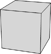
}Here, we are creating a WireCube object and Cube object at the same position in space. The wire cube uses the same WireframeMaterial object seen before to define the color of the segments in the WireCube primitive, while the regular cube uses a ColorMaterial object for defining the color of the faces used in the Cube primitive. Compiling the CombinedWireAndRegularCube example will display what appears to be a single cube with its edges outlined in black, as shown in Figure 4-3. The regular cube object is scaled to 0.99 of its original size by using the scale() method (available to any 3D object in Away3D). This is done to ensure the segments of the wire cube always overlay the faces of the regular cube. It is an amount large enough to influence the sorting order calculated by the Z-sorting algorithm but small enough to not be obviously visible in the scene.
Compare the output in Figure 4-3 with the previous rendering of a regular cube with a WireColorMaterial material in the CommonPrimitives example to see the visual difference between rendering with wire primitives and rendering outlined faces with regular primitives.
The segment element can be implemented as the building block of more user-defined geometry by using the LineSegment primitive class, also located in the away3d.primitives package. This creates a simple 3D line in space, by specifying the start and end point vectors. To experiment with this, let's create the following new document class extending Chapter04SampleBase:
package flash3dbook.ch04
{
  import away3d.core.math.*;
  import away3d.primitives.*;

  import flash3dbook.ch04.*;

  [SWF(width="800", height="600")]
  public class LinesInSpaceWithLineSegment extends Chapter04SampleBase
  {
    public function LinesInSpaceWithLineSegment ()
    {
      super();
    }

    protected override function _createScene() : void
    {
      var i : int, p1 : Number3D, p2 : Number3D, seg : LineSegment;

      p1 = new Number3D();
      p2 = new Number3D();

      for (i=0; i < 500; i++) {
        p2.x = (Math.random()-0.5) * 200;
        p2.y = (Math.random()-0.5) * 200;
        p2.z = (Math.random()-0.5) * 200;
p2.add(p2, p1);
seg = new LineSegment();
seg.start = p1;
seg.end = p2;
_view.scene.addChild(seg);
p1.clone(p2);
}
}
}
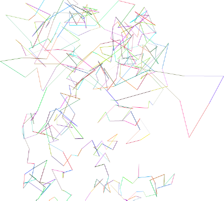
}Here, we create 500 LineSegment objects with Number3D objects used for the start and end positions of the line. It is ensured that the start property of the next LineSegment object is the same as the end property of the previous LineSegment object. This creates a continuous line moving between random points in space. Compiling the code should display the output shown in Figure 4-4.
Earlier in this chapter, we talked about the plane primitive having a square or rectangular shape to its sides. This is a restriction of the Plane class in Away3D, but it is also possible to create a plane with any number of sides using the RegularPolygon class. Here, the resulting convex geometry has rotational symmetry, forming a mesh in the shape of a pentagon, hexagon, octagon, and so on. The number of sides is set by the sides property of the RegularPolygon object.
To explore the different results possible, let's create a new document class by extending Chapter04SampleBase:
package flash3dbook.ch04
{
import away3d.materials.*;
import away3d.primitives.*;
import flash3dbook.ch04.*;
[SWF(width="800", height="600")]
public class PolygonsWithRegularPolygon extends Chapter04SampleBase
{
public function PolygonsWithRegularPolygon ()
{
super();
}
protected override function _createScene() : void
{
//create a pentagon
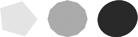
_createPoly(5, 0xdddddd, −250);
//create a dodecahedron
_createPoly(12, 0x999999, 0);
//create a circle
_createPoly(100, 0x222222, 250);
}
protected function _createPoly(sides : int, color : int, x : Number) : void
{
var polygon : RegularPolygon;
polygon = new RegularPolygon();
polygon.sides = sides;
polygon.material = new ColorMaterial(color);
polygon.x = x;
polygon.yUp = false;
polygon.bothsides = true;_view.scene.addChild(polygon);
}
}
}In the preceding code, creation of the various RegularPolygon objects has been broken out into a separate class method called _createPoly(), which accepts three arguments: sides, color, and x. Each RegularPolygon object is created inside this method using the sides argument for its number of sides, color argument for its material color, and x argument for its X axis position. Aside from these properties, each new object also has its yUp property set to false and bothsides property set to true, in much the same way our Plane object had in the CommonPrimitives example earlier in this chapter.
Using the _createPoly() method, three RegularPolygon objects are created with varying numbers of sides and varying material color. Compiling the example should display the image shown in Figure 4-5.
Like the common primitives explored earlier, the RegularPolygon primitive has a line segment equivalent called WireRegularPolygon. To see it in action, replace the contents of the _createPoly() method with the following code:
var wirePolygon : WireRegularPolygon;

wirePolygon = new WireRegularPolygon();
wirePolygon.sides = sides;
wirePolygon.material = new WireframeMaterial(color);
wirePolygon.x = x;
wirePolygon.yUp = false;
wirePolygon.bothsides = true;

view.scene.addChild(wirePolygon);
Here, we have replaced all RegularPolygon objects with WireRegularPolygon objects and the ColorMaterial with a WireframeMaterial. The resulting geometry on compiling is identical to that shown in Figure 4-5, only now the primitives are drawn using segments instead of faces as their mesh elements.
Primitives are a good starting point for geometry creation in Away3D and can be extremely useful in creating basic 3D effects. But let's face it; they can only take us so far. For more advanced 3D scenes, such as those required in game development, the 3D content we want will require more complexity. In these cases, it is usually necessary to create the model geometry using software dedicated to the task and then save the result it in a 3D file format that Away3D can understand.
Luckily, Away3D supports most major 3D formats, making it compatible with virtually every piece of 3D modeling software available. Table 4-1 lists some of the major software packages next to the compatible export options available for use in Away3D. As well as importing files, there is also a neat way to embed models directly into an Away3D project, which is covered in the next section.
Table 4.1. Major 3D Modeling Software Titles Alongside Available Away3D File Export Options
Software | Away3D-Compatible Formats |
|---|---|
Maya | OBJ and COLLADA (requires plug-in) |
3ds Max | OBJ, 3DS, and COLLADA (requires plug-in) |
SoftImage | OBJ, 3DS, and COLLADA |
Cinema4D | COLLADA and 3DS |
LightWave | OBJ and COLLADA |
Blender | COLLADA, OBJ, 3DS, and ActionScript (requires plug-in) |
Google SketchUp | KMZ, COLLADA, OBJ, and 3DS |
The loading and parsing procedure for 3D files in Away3D is the same regardless of format. It consists of five steps:
Create a loader object.
Create a parser object.
Link the parser object to the loader object.
Set up event listeners on the loader object.
Define the file path of the object to be loaded and commence loading.
To maintain a level of continuity, Away3D uses an approach for loading 3D content similar to the display list's approach for loading 2D content with the native Loader class in Flash. Because the object that is being loaded is unavailable until the loading finishes, the actual loader object serves as a placeholder that can be added to the scene. Let's have a look at some familiar code when working with images in Flash.
var loader : Loader = new Loader();
loader.contentLoaderInfo.addEventListener(Event.COMPLETE, _onComplete);
loader.load(new URLRequest('image.jpg'))
addChild(loader);
This approach of triggering the download and adding the loader to the display list (regardless of whether the object has finished loading) is handled exactly same way in Away3D.
var loader : Loader3D = new Loader3D();
loader.addEventListener(Loader3DEvent.LOAD_SUCCESS, _onSuccess);
loader.loadGeometry("model.3ds", new Max3DS());
scene.addChild(loader);
The biggest difference arises from Away3D having separate parsing classes for interpreting the results of loading, while Flash automatically detects the content type and parses it accordingly. In the preceding Away3D example, the parser is defined as a new Max3DS object in an argument of the loadGeometry() call, which tells the engine to use the 3DS parser when reading the loaded file.
All parsers and loaders in Away3D are found in the away3d.loaders package. Loader3D is the default loader, acting in much the same way as the native Loader class. LoaderCube is a specialized loader class that acts as a 3D loading indicator that is visible throughout the loading process. Let's create an example using the LoaderCube object by extending the Chapter04SampleBase class and overriding the _createScene() method.
package flash3dbook.ch04
{
import away3d.containers.*;
import away3d.core.base.*;
import away3d.core.utils.*;

import away3d.events.*;
import away3d.exporters.*;
import away3d.loaders.*;

import flash.system.*;
import flash.events.*;

import flash3dbook.ch04.*;
  [SWF(width="800", height="600")]
  public class LoadingExternalModels extends Chapter04SampleBase
  {
  private var _loader:LoaderCube;
    public function LoadingExternalModels ()
    {
      super();
    }

    protected override function _createScene() : void
    {
    _loader = new LoaderCube();
var url : String = '../../assets/ch04/monkey.3ds';
_loader.addEventListener(Loader3DEvent.LOAD_SUCCESS, _onSuccess);
_loader.loadGeometry(url, new Max3DS());
_loader.scale(10);
_view.scene.addChild(loader);
}
protected function _onSuccess(ev : Loader3DEvent) : void
{
trace('Finished loading!')
}
}
}In the preceding code, the monkey.3ds model is obtained from the chapter resource files. This is a zip file containing all content used in the chapter and can be downloaded along with all other chapters resources for the book from the downloads section of www.friendsofed.com. Once you have the chapter files on your local machine, make sure that the file path written for the url property matches the path to your local file. Because monkey.3ds is being loaded at runtime, the path must be correct from the location of the compiled SWF file.
Compiling the example will display the loading indicator as it tracks loading progress. Once the model finishes loading, it replaces the loading indicator on screen. You should also see the trace output Finished loading! appear in the console window. Because loading a file from a location on your local machine is very fast, the LoaderCube object may not get a chance to display its loading indicator before the content completes loading. If you want a closer look at the LoaderCube object, you may have to upload the monkey model to a location online in order to slow down its loading progress. However, it is easy to see the LoaderCube object when a load fails, because it doesn't ever get replaced by the loading model. Typing an incorrect file path in the url property and recompiling will display a red cube with an error message printed on it. This visual state is taken by the LoaderCube object when a load fails for any reason and can be useful when debugging an Away3D application.
Few 3D file formats come optimized for use on the Web or for use with Flash. Some are not designed with limited bandwidth in mind, like the verbose COLLADA format. Others rely on binary decompression algorithms like ZIP that require extra processing to decompress, slowing down parsing times.
For these reasons, Away3D offers an export option that can process 3D model data already in Away3D's scene graph and output it as an ActionScript class. The process uses the AS3Exporter class located in the away3d.exporters package and requires only a few steps to carry out the conversion:
Load your 3DS, COLLADA, or similar model into Away3D using the
Loader3Dclass.Use the
AS3Exporterclass to convert the model data to ActionScript code, and paste the output to the clipboard.Create a new class file in your project folder, and paste the contents of the clipboard into the class.
Recompile your project, this time creating the model by instantiating the newly created class, instead of loading a separate file.
Once this process has been carried out on your model files, you can easily embed your model in your SWF application file or compile a separate SWF that can then be loaded using the regular Flash Loader class. SWF files are compressed using ZIP and are very compact as a result, plus the decompression occurs natively in the Flash Player, so it's extremely fast! As well as this, parsing the model data is highly efficient because of the optimized methods contained in the created class file.
Note
The open-source 3D modeling package Blender can export to Away3D-compatible ActionScript files directly, taking away the need for the first three steps in the AS3Exporter optimization process. This requires a plug-in script written by Dennis Ippel, available from www.rozengain.com.
As an example of the conversion process, let's now use the AS3Exporter class to create an ActionScript version of our monkey.3ds file by building on the previous LoadingExternalModels example. Add the following line of code to the end of the _onSuccess() method:
stage.addEventListener(MouseEvent.CLICK, _onClick);
Because we are copying text to the clipboard, the process needs to be triggered by user interaction. We therefore use a CLICK event handler to avoid a security error. In the preceding code, we have set up a listener for the mouse event using a handler called _onClick(). We now need to create the _onClick() method used to receive this event, by adding the following code to the end of the LoadingExternalModels class definition.
protected function _onClick(ev : MouseEvent) : void
{
                var exporter:AS3Exporter = new AS3Exporter();
                exporter.addEventListener(ExporterEvent.COMPLETE, _onComplete);
                exporter.export(_loader.handle, 'MonkeyMesh', 'flash3dbook.common'),
}

protected function _onComplete(ev : ExporterEvent) : void
{
                trace('Export completed!'),
                System.setClipboard(ev.data);
}
The AS3Exporter class is configured to produce an ActionScript file called MonkeyMesh that is contained in a package named flash3dbook.ch04. After executing the AS3Exporter with the export() method, the _onComplete() handler method is triggered, and the generated class string is extracted from the data property of the ExporterEvent object. This is then placed in the system clipboard, ready for you to paste into a newly created class file.
In your ActionScript editor of choice, create a new class file called MonkeyMesh in the package flash3dbook.common, and paste in the contents of the clipboard (usually performed by the keyboard shortcut CTRL+V on Windows or CMD+V on Mac OS X). Note that what has been created by the AS3Exporter is a well-formed, ready-to-compile class definition using the name and package strings supplied in our previous _onClick() method definition.
To use the file in an Away3D project, simply instantiate the MonkeyMesh class, and add it to the scene as you would any other 3D object. In this case, only a simple mesh was exported, but there is no limit to the complexity of the output—we could have converted a container object with an entire scene enclosed if we had wanted.
With an ActionScript model, it is extremely easy to create copies of the model at runtime by instantiating the class over and over. Let's create an example using our newly generated MonkeyMesh object by extending the Chapter04SampleBase class and overriding the _createScene() method:
package flash3dbook.ch04
{
  import away3d.core.base.Mesh;
  import away3d.lights.*;
  import away3d.materials.*;

  import flash.display.*;
  import flash.events.*;
  import flash.net.*;
  import flash.utils.*;

  import flash3dbook.common.*;

  [SWF(width="800", height="600")]
  public class LoadingAS3Models extends Chapter04SampleBase
  {
    public function LoadingAS3Models ()
    {
      super();
    }

    protected override function _createScene() : void
    {
      var i : int;
      var material : ShadingColorMaterial = new ShadingColorMaterial(0x888888);
      for (i=0; i < 5; i++) {
        var monkeyMesh : MonkeyMesh = new MonkeyMesh();
        monkeyMesh.material = material;
        monkeyMesh.x = (Math.random()-0.5) * 400;
monkeyMesh.y = (Math.random()-0.5) * 400;
monkeyMesh.z = (Math.random()-0.5) * 400;
_view.scene.addChild(monkeyMesh);
}
var light : PointLight3D = new PointLight3D();
light.x = 300;
light.z = −400;
light.y = 500;
_view.scene.addLight(light);
}
}
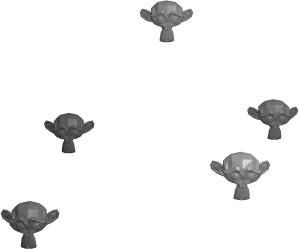
}Notice how each monkeyMesh model is created by instantiating a new monkeyMesh object inside a for loop. Compiling the code will create five randomly spaced MonkeyMesh models with a grey ShadingColorMaterial applied, as shown in Figure 4-6.
Note
As an alternative to the method of using the AS3Exporter class described here, there is an Adobe AIR utility, called Prefab3D, available from the Away3D website that will let you create ActionScript model classes by simply dragging and dropping model files.
When using a large number of ActionScript models, it is a good idea to embed them in a separate SWF file to get the best of both worlds: a quick initial load combined with small, efficient model files loaded incrementally. The idea of using a separate SWF file as an asset library is certainly not unique to the world of 3D, but it is a concept that fits perfectly with the use of 3D ActionScript models.
When loading an external SWF file in Flash with the native Loader class, all assets embedded within that SWF are made available to the running application. This includes graphics and sounds, as well as any ActionScript classes defined by the SWF's source code. Let's create a library SWF file containing our model and then use it in our LoadingAS3Modelsexample.
Create the new document class MyLibraryClass in the package flash3dbook.ch04 with the following code:
package flash3dbook.ch04
{
  import flash3dbook.common.*;

  import flash.display.*;

  public class MyLibraryClass extends MovieClip
  {
    // Force mesh classes to be included in the SWF
    private var mesh01 : MonkeyMesh;
  }
}
Compile this into our model library SWF file called assets.swf. Obviously, a library SWF such as this would normally contain more than one model! We can now use this in our LoadingAS3Models example by replacing the _createScene() method with the following code:
protected override function _createScene() : void
{
  var loader : Loader = new Loader();
  loader.contentLoaderInfo.addEventListener(Event.COMPLETE, _onComplete);
  loader.load(new URLRequest('assets.swf'));
}
Once the load is complete, any classes in the loaded SWF will be available to the main application. In the preceding code, we have defined an event handler for the COMPLETE event called onComplete(). We now need to create this method by adding the following code to the end of the LoadingAS3Models class definition.
private function _onComplete(ev : Event):void
{
  var MClass : Class;
  MClass = getDefinitionByName('flash3dbook.common.MonkeyMesh') as Class;
  var monkeyMesh : Mesh = new MClass();
  _view.scene.addChild(monkeyMesh);
}
To avoid errors at compile time (and to avoid inadvertently compiling MonkeyMesh with our document class), we need to extract the MonkeyMesh class definition using the Flash utility function getDefinitionByName(). This method takes the string supplied in its argument and returns the class or object instance defined by that string. Calling getDefinitionByName() here returns a reference to the MonkeyMesh class and stores it in the MClass variable. We then invoke the MClass constructor to create a new instance of the MonkeyMesh class, which can be cast to Mesh (its inherited object type) and added to the scene. Compiling the code will display the same result as before, but without the LoaderCube placeholder because, in this case, the loading is handled by the native Loader class.
Bitmap filter effects (blurs, glows, drop shadows, etc.) that you are familiar with applying to display list objects in Flash will work just as well applied to scene graph objects in Away3D. In fact, the way they are applied is identical to display list objects, and the exact same filter classes from the flash.filters package can be used. Let's create an example to demonstrate this feature:
package flash3dbook.ch04
{
import away3d.primitives.*;
import away3d.materials.*;
import flash3dbook.ch04.*;
import flash.filters.*;
[SWF(width="800", height="600")]
public class BitmapFilterModels extends Chapter04SampleBase
{
public function BitmapFilterModels ()
{
super();
}
protected override function _createScene() : void
{
var cube : Cube = new Cube();
cube.material = new ColorMaterial(0xcccccc);
cube.filters = [ new GlowFilter(0) ];
cube.ownCanvas = true;
_view.scene.addChild(cube);
}
}
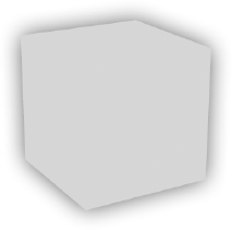
}Compiling the preceding code will display the output shown in Figure 4-7. As well as applying filters in an array object using the familiar filters property, we need to explicitly tell Away3D to render the 3D object in a separate Sprite object using the ownCanvas property. When ownCanvas is set to true, a designated Sprite object is created to act as a wrapper for the visible output of the 3D object, and the filter array is automatically applied to this wrapper to render the contained filter effects.
The disadvantage of using the ownCanvas property to enable filter effects on 3D objects is the limitation it imposes on Z sorting. With the visible output of an object grouped into a Sprite container, we lose the ability to individually sort each face (or segment) element of the object with other object's elements, restricting the Z-sorting algorithm to only deal with the object as a single sorted entity. This can lead to unwanted sorting artifacts if, for example, two 3D objects exist as two intersecting meshes that require different sorting depths across their elements. The solution is to only apply ownCanvas to objects that need it, splitting objects that could cause sorting problems into separate meshes that make more sense to the Z-sorting algorithm.
As mentioned earlier, when dealing with 3D, the term sprite generally refers to a 3D object represented by a 2D image projected onto a flat plane. The most basic type of sprite is a billboard (or spherical) sprite, which operates by ensuring its 2D image is always rendered facing the camera. Sprites are regularly used for optimizing the rendering process, by faking the appearance of more complex objects that look essentially the same from all angles.
Examples of 3D objects that can potentially take advantage of the sprite approach to rendering are trees and smoke. Trees are typically implemented using cylindrical sprites that turn to face the camera around a restricting axis, because trees can be considered to have axial symmetry. Smoke can be created using spherical sprites that always face the camera, because a cloud of smoke can be considered to have spherical symmetry.
There are many complex ways to create realistic smoke effects using particle engines, but in applications where performance is of extreme importance (such as computer games and real-time 3D on the Web), scattering large spherical sprites is perhaps the most popular method of faking it.
A basic 3D sprite in Away3D is created using the Sprite3D class located in the away3d.sprites package and uses a material object to define its 2D image. There is also a 3D sprite variant called MovieClipSprite that uses a native Sprite object as its 2D image; this has some advantages over Sprite3D, such as faster animation and interaction, but comes with the restriction of allowing only one MovieClipSprite per Sprite source, and when using Flash 9, only in spherical sprite mode. Since the puffs of smoke in our example will be static, we'll use the more applicable Sprite3D class.
Let's begin by creating a sample class that create a large number of sprites and scatters them randomly around the scene origin.
package flash3dbook.ch04
{
  import away3d.sprites.*;
  import away3d.materials.*;

  import flash.display.*
  import flash.filters.*;
  import flash.geom.*;

  [SWF(width="800", height="600")]
  public class SmokeWithSprites extends Chapter04SampleBase
  {
    private var _material : BitmapMaterial;

    public function SmokeWithSprites ()
    {
      super();
    }

    protected override function _createScene() : void
    {
      _createMaterial();
      var i : int;

      for (i=0; i<50; i++) {
        var sprite : Sprite3D = new Sprite3D(_material);

        sprite.x = (Math.random()-0.5) * 200;
        sprite.y = (Math.random()-0.5) * 200;
        sprite.z = (Math.random()-0.5) * 200;

        _view.scene.addSprite(sprite);
      }
    }

    protected function _createMaterial() : void
    {
      var bmp : BitmapData = new BitmapData(100, 100, false,  0xffffff*Math.random());
      _material = new BitmapMaterial (bmp);
    }
0xffffff*Math.random());
_material = new BitmapMaterial (bmp);
}} }
Notice that in our _createScene() method, we use a similar technique to the one in the LoadingAS3Models example, with a for loop creating objects and assigning them random positions. In this case, the objects are 3D sprites. One notable difference is that instead of using the addChild() method to include our 3D sprites in the scene, we use an addSprite() method.
Compiling the preceding code will display 50 randomly colored 100 × 100–pixel squares, scattered randomly within a 100-unit cube area centered around the scene's origin. Moving our mouse over the scene will rotate the cloud of sprites to show you that they are indeed positioned in 3D space. Sprites further away from the camera will appear smaller than sprites closer to the camera, but they still feel very 2D because a flat color is hardly representative of an object with spherical symmetry.
The next step is to create a texture for the sprites that resembles a puff of smoke. To achieve this, replace the contents of the _createMaterial() method in the SmokeWithSprites example with the following code:
var puff : Shape = new Shape(); var dia : Number = Math.random() * 40 + 30; puff.graphics.beginFill(0xcccccc, Math.random()); puff.graphics.drawEllipse(-dia/2, -dia/2, dia, dia); var bmp : BitmapData = new BitmapData(100, 100, true, 0); bmp.draw(puff, new Matrix(1, 0, 0, 1, 50, 50)); var blur : BlurFilter = new BlurFilter(32, 32, 2); bmp.applyFilter(bmp, bmp.rect, new Point, blur); _material = new BitmapMaterial (bmp);
Here, the smoke material is created by first drawing a circle using the ActionScript drawing API. The circle has a diameter of anywhere between 40 and 70 pixels and is colored gray with a random level of transparency. The circle is then drawn into a bitmap data object, and a blur effect is applied to give it a hazy look.
Recompiling the SmokeWithSprites example now generates 50 randomly sized puffs of smoke, scattered across the same 3D space as before. The overall effect should be one of a 3D smoke cloud that can be rotated with the mouse to view it from all angles. Figure 4-8 depicts the result.
Because 3D sprites are a general technique for the fast rendering of complex objects, we could increase the complexity of the effect in the SmokeWithSprites example to create a greater sense of realism, without running into too many performance problems. For example, the cloud could be animated or have filter effects applied to produce something even more abstract.
At this stage, you are hopefully starting to feel confident about creating 3D objects in Flash. But so far, we have yet to build a practical application. For this, we need to look at creating a more complex example.
One very typical use for Flash on the Web is as an image gallery interface. There are many different ways to implement this type of interface in Flash, so to stand out from the crowd, we will need one that is a bit.... twisted. This project pulls together several of the topics we have covered in this chapter, so it should serve as a nice recap. We will use the following features and workflows in the production of our image gallery:
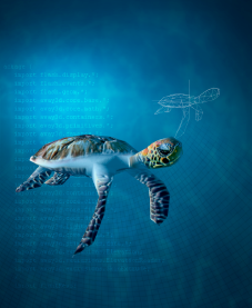
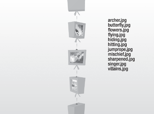
The gallery images will be displayed inside TV screens, which are stacked on top of each other and randomly rotated around the Y axis. The user navigates the image gallery with a simple menu built from Flash text fields or using the mouse to spin the hover camera around, panning up and down through the images. Have a look at Figure 4-9 for a sneak preview of the completed application.
The application is built from four classes, all located in the flash3dbook.ch04.tutorial package:
TwistedImageGallery: The main application class that is responsible for creating all content, using an array of images namesTVBox: Represents a single TV object that groups the elements making up a single TV into an object containerTVBoxMesh: The mesh data of the TV model as an ActionScript class, created using theAS3ExporterclassImageMenuItem: A single menu item that holds a reference to its associated TV container and handles basic user interaction, such as rollover effects
Let's begin by looking at the document class TwistedImageGallery, which is responsible for setting up all content, including the Away3D view and text-based menu:
package flash3dbook.ch04.tutorial
{
import away3d.cameras.*;
import away3d.containers.*;
import away3d.core.base.*;
import away3d.lights.*;
import away3d.primitives.*;
import flash3dbook.ch04.tutorial.*;
import flash.display.*;
import flash.events.*;
import flash.geom.*;
import flash.filters.*;
[SWF(width="800", height="600")]
public class TwistedImageGallery extends Sprite
{
private var _view : View3D;
private var _camera : HoverCamera3D;
public function TwistedImageGallery()
{
super();
_createScene();
_createContent();
}
private function _createScene() : void
{
_camera = new HoverCamera3D();
_camera.distance = 600;
_camera.tiltAngle = 0;
_camera.steps = 4;
_view = new View3D();
_view.x = 400;
_view.y = 300;
_view.camera = _camera;
addChild(_view);
addEventListener(Event.ENTER_FRAME, _onEnterFrame);
// Light positioned up and back, to shade the scene
var light : PointLight3D = new PointLight3D();
light.ambient = 0.8light.position = new Number3D(1000, 500, −1000);
_view.scene.addLight(light);
// Beautiful gradient background
var matrix : Matrix = new Matrix();
matrix.createGradientBox(800, 600, Math.PI/2);
graphics.beginGradientFill(GradientType.LINEAR,
[0xffffff, 0xdddddd], [1,1], [0, 0xff], matrix);
graphics.drawRect(0, 0, 800, 600);
}
private function _createContent() : void
{
}
private function _onEnterFrame(ev : Event) : void
{
if (stage.mouseX < 160 || stage.mouseX > 640)
_camera.panAngle += (stage.mouseX - stage.stageWidth/2) / 60;
_camera.hover();
_view.render();
}
}
}The preceding code defines the shell of the TwistedImageGallery class. On instantiation, the constructor calls two initializing methods, _createScene() and _createContent(). The _createContent() method currently exists as a stub that will be added to later. Inside the _createScene() method, we have the basic code for setting up our view.
First, a hover camera is created and has its distance, tiltAngle, and steps properties initialized to what we want for the camera movement. Next, the view is created and positioned at the center of the stage, with its camera property set to our newly created HoverCamera3D object.
As we have come to expect, an ENTER_FRAME listener is created to allow us to update the hover camera position and invoke the render() method of the view on every frame of the Flash movie. The handler method _onEnterFrame rotates the camera relative to the x coordinate of the mouse, with some restrictions on maximum and minimum rotation to keep the motion under control.
Next, a light source is added to the scene in the form of a PointLight3D object that will be used by any shading materials we assign to a mesh. Lights and shading materials are covered in greater detail in Chapter 5.
Finally, a subtle gradient is drawn across the entire stage background using the standard ActionScript drawing API, to add some variation to the background of the scene.
Now, let's prepare the external model to be used for the 3D TV set. We want to use an ActionScript class of the mesh, which can be created with the tvbox.3ds file downloaded in the chapter resource files mentioned earlier. Conversion can be done using the AS3Exporter class, the Blender export scripts, or the export utility from www.away3d.com. In this case, we'll take a look at the AS3Exporter approach, which requires a modification to our previously created LoadingExternalModels example to convert our tvbox.3ds file.
Note
If you have not already created the LoadingExternalModels example from earlier in this chapter, you can skip this step by using the ready-made TVBoxMesh file supplied with the chapter download files, available from the downloads section of www.friendsofed.com.
In the _createScene() method of our LoadingExternalModels example, replace the url variable definition with the following code:
var url : String = 'http://flash3dbook.com/files/chapter4/tvbox.3ds';
We also need to adjust the output name of the ActionScript file, which can be done by replacing the contents of the_onClick() method with the following code:
new AS3Exporter(loader.handle, 'TvBoxMesh', 'flash3dbook.ch04.tutorial'),
Recompiling the LoadingExternalModels example imports the tvbox.3ds file into the Flash movie. Once it is loaded, click the mouse anywhere on the stage to copy the ActionScript class definition TVBoxMesh to the clipboard. In your ActionScript editor, create a new class called TVBoxMesh in the package flash3dbook.ch04.tutorial, and paste in the clipboard contents. Save the file, and you're ready to use the TVBoxMesh class in the application.
Next, we need to create the container for the elements of a single TV item in the gallery, called TVBox. This class extends ObjectContainer3D, which allows us to group several elements in a scene simply by adding them as children of the container. Wrapping 3D objects in this manner is a common practice when creating complex, reusable 3D assets. We'll start by creating the shell of the TVBox class.
package flash3dbook.ch04.tutorial
{
  import away3d.containers.*;
  import away3d.materials.*;
  import away3d.primitives.*;

  import flash.display.*;
  import flash.events.*;
  import flash.net.*;

  public class TVBox extends ObjectContainer3D
  {
    public function TVBox(imageUrl : String)
{
super();
_createChildren();
_loadImage(imageUrl);
}
private function _createChildren() : void
{
}
private function _loadImage(url : String) : void
{
}
}
}As you can see, the constructor takes one parameter—the URL string of the image that the TV is to display. This is passed to the _loadImage method, which currently exists as a stub that we will fill out shortly. Before that, the constructor calls the _createChildren method, inside which we wish to create the visual assets of the TVBox class from three pieces:
The TV box and stand are both parts of the mesh geometry encoded in the
TVBoxMeshActionScript class, which is built automatically on instantiation.The TV picture is the gallery image, made from a simple plane primitive configured with a bitmap material.
The TV antenna is a flat PNG, drawn using a
Sprite3Dobject and positioned on top of the TV box.
Starting with the creation of the TV box and stand, we add the following code to the _createChildren() method:
var tv : TVBoxMesh = new TVBoxMesh();
tv.material = new ShadingColorMaterial(0xcccccc);
tv.scale(30);
addChild(tv);
An instance of the TVBoxMesh class is created, and its material property is set to a new ShadingColorMaterial object. We then adjust its scaling to 30 times the default, because the original model was created in a modeling application with a world scale different from the one used here.
Next, we create a plane primitive representing the TV screen, onto which the loaded image will be mapped. Because we want to have easy access to the plane both now and later when the image finishes loading, the first thing we do is to create a global class variable inside the definition of the TVBox class, that will hold the plane primitive instance.
private var _image : Plane;
With this done, we can now create the plane primitive by adding the following code to the _createChildren() method:
_image = new Plane();
_image.yUp = false;
_image.width = 50;
_image.height = 50;
_image.x = 2;
_image.z = −10;
_image.pushback = true;
_image.material = new ColorMaterial(0x000000);
addChild(_image);
The plane is built facing forward rather than up (thanks to yUp being set to false) and is placed in a suitable position with regard to the geometry of the TVBoxMesh object. For now, it is uses a black color material, but this will be reset once our gallery image is loaded. By setting the pushback property to true, we ensure that the image is never drawn on top of the TV mesh. This could have been a problem when the TV is rendered from behind, but because backface culling will render the plane invisible from those angles, we can safely use this method to prevent Z-sorting artifacts from faces being too close to each other.
Finally, we build the antenna for the TV using the image antenna.png, which is distributed inside the same chapter download files mentioned before. We embed the image into the SWF by adding an ActionScript [Embed] meta-tag inside the definition of the TVBox class.
[Embed('../../../../assets/ch04/tutorial/antenna.png')]
private var AntennaBitmap : Class;
This will assign a bitmap asset definition to the AntennaBitmap variable as if it were a regular class definition. Instantiating the class referenced by this variable will create a new BitmapAsset object— a class definition that extends the standard Bitmap class in Flash.
Note
The [Embed] meta-tag is available for use in the Flex SDK and can be used with the most recent Flash editors, including Flash Professional CS4 and CS5. Flash Professional CS3, however, does not support this syntax. To compile using CS3, import the image as a library item and set its linkage class name to AntennaBitmap. This approach achieves essentially the same outcome as using Embed in the previous code.
We can now create the 3D sprite for the antenna by adding the following code to the _createChildren method:
var bmp : BitmapData = Bitmap(new AntennaBitmap()).bitmapData;
var spriteMaterial : BitmapMaterial = new BitmapMaterial(bmp);
spriteMaterial.smooth = true;
var antenna : Sprite3D = new Sprite3D(spriteMaterial);
antenna.scaling = 0.15;
antenna.y = 40;
addSprite(antenna);
This creates a new bitmap material using the bitmap data extracted from an instance of the AntennaBitmap class and uses it as the material definition of a new 3D sprite object. The material has smoothing enabled to keep the bitmap from looking pixilated, and the antenna is scaled and positioned to align neatly with the top of the TVBoxMesh object.
To handle the loading of the gallery images, we need to add the following code to the _loadImage method of the TVBox class:
var loader : Loader = new Loader();
var info : LoaderInfo = loader.contentLoaderInfo;

info.addEventListener(Event.COMPLETE, _onImageComplete);
info.addEventListener(IOErrorEvent.IO_ERROR, _onImageError);
loader.load(new URLRequest(url));
This defines a new native Loader object that takes the urlargument of the method and creates a new URLRequest object for the loader. Before the load is triggered, two handler functions, _onImageComplete() and _onImageError(), are set to trigger from COMPLETE and IO_ERROR events dispatching from the loader. We now need to create these functions by adding the following code to the end of the LoadingExternalModels class definition:
private function _onImageComplete(ev : Event) : void
{
  var info : LoaderInfo = ev.currentTarget as LoaderInfo;
  var bmp : BitmapData = Bitmap(info.loader.content).bitmapData;
  var imageMaterial : BitmapMaterial = new BitmapMaterial(bmp);
  imageMaterial.smooth = true;
  _image.material = new BitmapMaterial(bmp);
}
private function _onImageError(ev : Event) : void
{
  trace("Error loading image");
}
In the preceding _onImageComplete method, the BitmapData object is retrieved from the loaded bitmap and used to create a new bitmap material for the _image plane. The _onImageError method traces an error message to the output window so that we are notified if the application has had a problem loading its images.
So far, we have yet to see the result of the TVBox class created in the last section. Before we start to piece everything together in the document class, we need to create one more subclass that represents an item in the navigation menu. This is constructed as an extension of the Sprite class, with a text field contained within and some very simple mouse interaction.
package flash3dbook.ch04.tutorial
{
  import flash.display.*;
  import flash.events.*;
import flash.text.*;
import flash.filters.DropShadowFilter;
import flash.utils.getTimer;
public class ImageMenuItem extends Sprite
{
private var _tv : TVBox;
private var _tf : TextField;
public function ImageMenuItem(str : String, tv : TVBox)
{
_tv = tv;
_createText(str);
}
private function _createText(str : String) : void
{
_tf = new TextField();
_tf.defaultTextFormat = new TextFormat('Arial', 11);
_tf.autoSize = TextFieldAutoSize.LEFT;
_tf.text = str;
_tf.selectable = false;
_tf.mouseEnabled = false;
addChild(_tf);
addEventListener(MouseEvent.MOUSE_OVER, _onMouseOver);
addEventListener(MouseEvent.MOUSE_OUT, _onMouseOut);
}
public function get tv() : TVBox
{
return _tv;
}
private function _onMouseOver(ev : MouseEvent) : void
{
_tf.textColor = 0x666666;
}
private function _onMouseOut(ev : MouseEvent) : void
{
_tf.textColor = 0;
}
}
}The class constructor requires two arguments: one for the text displayed by the menu item and the other for the instance reference of the TVBox container representing the gallery item. First, we save the reference to the TVBox instance as a local variable. Next, the _createText() method is called; it creates a new TextField object and adds it to the display list. Event listeners for MOUSE_OVER and MOUSE_OUT events are added, which change the color of the text to gray when the over event is triggered and back to black when the out event is triggered.
Now that we have our TVBox and ImageMenuItem classes defined, we can glue everything together with the TwistedImageGallery document class.
To start testing the visual output of what we have been building, we need to fill the empty _createContent method with the code that will instantiate both the TVs and the menu items.
The TV objects will be added to the scene within a single container, allowing us to simultaneously pan all 3D content up and down through the gallery images. Because this container needs to be accessed from several methods, we create it in a global variable added to the TwistedImageGallery class definition.
private var _pivot : ObjectContainer3D;
The _pivot container instance is created along with the rest of the application content by adding the following code to the _createContent method:
var i : int;
var last_angle : Number = 0;
var images : Array = [
  'archer.jpg',
  'butterfly.jpg',
  'flowers.jpg',
  'flying.jpg',
  'hiding.jpg',
  'hitting.jpg',
  'jumprope.jpg',
  'mischief.jpg',
  'sharpened.jpg',
  'singer.jpg',
  'villains.jpg'
];

_pivot = new ObjectContainer3D();
_view.scene.addChild(_pivot);

for (i=0; i < images.length; i++) {
  var url_base : String = '../../../../assets/ch04/tutorial/';
  var tv : TVBox = new TVBox(url_base + images[i]);
  tv.y = -i*100;
  tv.rotationY = last_angle + Math.random() * 90 + 45;
  last_angle = tv.rotationY;
  _pivot.addChild(tv);

  var item : ImageMenuItem = new ImageMenuItem(images[i], tv);
item.x = 550; item.y = i*18 + 140; item.buttonMode = true; item.addEventListener(MouseEvent.CLICK, _onClickMenuItem); addChild(item); }
In the preceding code, each entry in the images array has corresponding TVBox and ImageMenuItem objects created. The TVBox objects are added to the _pivot container, and the ImageMenuItem objects directly to the stage.
Note
For the purposes of this example, the file names of the images have been hard-coded straight into an array in the application source. In a real-world application, it may be more useful to make this data source configurable using some external file definition, such as an XML document. Note that your path in the url_base variable may differ from the one that we have here. Make sure that you enter the correct path to your tutorial files
The TVs are oriented somewhat randomly by rotating each model between 45 and 90 degrees relative to the previous one, around the Y axis. The URL used to load each image is prefixed with a base URL pointing to the location of the local sample files.
The menu items are positioned on the stage as a simple vertical list. Each item has a listener function called _onClickMenuItem() that is set to trigger from a CLICK event. To allow us a test compile at this point with no errors, we can create an empty _onClickMenuItem() method by adding the following code to the end of the TwistedImageGallery class definition.
private function _onClickMenuItem(ev : MouseEvent) : void
{
}
Compiling the class will display the result shown in Figure 4-10. Moving the mouse left and right over the stage rotates the column of TVs left and right. To complete the gallery, we need to add code to the inside of the _onClickMenuItem() method that will allow us to navigate between each gallery item.
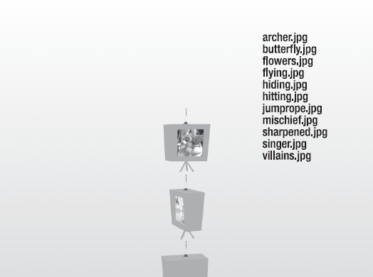
The movement we wish to add to the application will be triggered when the user clicks a menu item. We want to rotate the camera until it faces the TV screen corresponding to the item clicked and pan the _pivot container up or down so that the selected TV ends up at the center of the stage. As an extra subtlety, we will give the selected model a drop shadow filter to lift it off the page.
To react to a CLICK event from a menu item, we need to add some code to the _onClickMenuItem() method. Before we do that, let's define three new global class variables that will be used here and elsewhere in the TwistedImageGallery class.
private var _target_y : Number = 0;
private var _flying_to_tv : Boolean;
private var _last_active_tv : TVBox;
Insert this code at the start of the class definition, and then add the following to the _onClickMenuItem() method:
var tv : TVBox = (ev.currentTarget as ImageMenuItem).tv;
if (_last_active_tv) {
  _last_active_tv.ownCanvas = false;
  _last_active_tv.filters = [];
}

tv.ownCanvas = true;
tv.filters = [new DropShadowFilter(0, 0, 0, 1, 16, 16, 0.5, 2)];

_flying_to_tv = true;

_target_y = -tv.y;
_camera.panAngle = tv.rotationY - 180;

_last_active_tv = tv;
In the preceding code, we grab a reference to the selected TV instance from the tv property of the ImageMenuItem object returned in the event's currentTarget property. Next, we reset the ownCanvas and filters properties of any previously selected TVBox object. The newly selected TVBox object has its ownCanvas and filters properties modified to enable the drop shadow filter effect, and the motion mode _flying_to_tv is set to true, informing the application to take control of the camera and container movements and temporarily deactivate all other user interaction.
Two properties are required to define the movement required to move to the selected TV screen. The _target_y variable stores the y coordinate that aligns the _pivot container object so that the selected TV is positioned at the center of the stage. The camera panAngle properties stores the rotation value required by the camera to face the selected TV's screen image. Each variable is used as the end value in a tweening movement so that the change in position is performed smoothly. In the case of panAngle, we use the built-in tweening methods of the HoverCamera3D class.
As a final step in the _onClickMenuItem() method, the _last_active_tv variable is updated to the currently selected TVBox object, so that its ownCanvas and filters properties can be reset on the next menu selection.
Now that we have defined the motion mode and variables of a menu item selection, we need to modify the _onEnterFrame() method so that it will disable the mouse-controlled camera panning motion when the TV selection motion is taking place. We also need to use our _target_y variable to define the position tween of the _pivot container. Replace the onEnterFrame() method with the following code:
private function _onEnterFrame(ev : Event) : void
{
  if (!_flying_to_tv) {
    if (stage.mouseY < 120 || stage.mouseY > 480) {
      var max_y : Number = _pivot.maxY - _pivot.minY - 100;

      _target_y += (stage.mouseY - stage.stageHeight/2) / 30;
      _target_y = Math.max(0, Math.min(max_y, _target_y));
    }

    if (stage.mouseX < 160 || stage.mouseX > 640)
      _camera.panAngle += (stage.mouseX-stage.stageWidth/2) / 60;
}
else if (Math.abs(_pivot.y-_target_y) < 0.5) {
_flying_to_tv = false;
}
_pivot.y += (_target_y - _pivot.y) / 4;
// Wobble a bit up and down
_pivot.y += 2 * Math.sin(getTimer() / 700);
_camera.hover();
_view.render();
}The previously existing code in _onEnterFrame() for the mouse-controlled camera motion is now accompanied by a control for moving the _pivot container up or down depending on the y coordinate of the mouse, all wrapped within an if statement that checks if the camera is already animating on its way to a selected TV. If it is, the mouse-controlled motion is skipped, and instead, a check is made to see if the automatic camera control has completed its tween. Only when the y position of the _pivot container is within a tolerance of 0.5 units to the _target_y property will control be handed back to the mouse.
Note
Notice that when the mouse-controlled motion is active, the total height of _pivot is calculated by subtracting its minY property from its maxY property. The same calculation can be made for width (maxX-minX) and depth (maxZ-minZ) of any 3D object in Away3D.
Following the if statement, the y position of the _pivot container is updated using the _target_y property, with a slight easing effect. It then has an offset applied using a sine wave output, to achieve a "hovering" motion effect as the TVs move. The calls to the hover camera update hover() and view rendering method render() at the end of the _onEnterFrame() method remain the same as before.
Recompiling the application, you should instantly see a difference in interaction as the TVs can now be moved up and down as well as rotated left and right with the mouse. Clicking a menu item will automatically animate the application to the correct viewing position for the selected TV. You have completed the creation of the twisted image gallery!
In this chapter, we have introduced and compared the most common types of 3D objects: primitives that are geometric shapes created internally and custom models created externally that can be either loaded at runtime or embedded within the application using a converted ActionScript model class. We have also created your first practical 3D application using Away3D.
This chapter included some new 3D terminology that may not be all that familiar. The important terms, concepts, and techniques are recapped in the following list that will hopefully assist the creative process when building your own 3D applications in Flash:
Vertices, faces, and segments are the most basic visual elements in any 3D model but are rarely accessed directly.
Primitives are basic 3D geometric shapes, such as spheres and planes, represented by classes located in the
away3d.primitivespackage.Polygons in Away3D are a particular type of primitive, represented by the
RegularPolygonandWireRegularPolygonclasses.Segments are used to draw the wire primitive classes and can form abstract networks by using the
LineSegmentclass.Custom models can be loaded from a variety of different file formats using
Loader3Dand the parsing classes available in theaway3d.loaderspackage.Encoding 3D geometry as an ActionScript model using the
AS3Exporterclass in theaway3d.exporterspackage has both size and speed benefits.3D sprites can be used to simplify and speed up the rendering of nondescript symmetric objects such as smoke clouds. A variety of different types of 3D sprite exist in the
away3d.spritespackage.
Later chapters will cover using other types of content in Away3D, such as vector graphics and text, and procedural meshes using more complex generative tools. Before that, Chapter 5 looks in more detail at how to use lighting and materials to improve the visual impact of a 3D project.