How can you allow a VXLAN fabric to talk to an external network? Which implementation options are available? This is what Chapter 5 is all about. When it comes to interfacing your fabric to an external network, designate your border leaf to perform this role. It doesn’t matter if your external network is running dynamic route protocols or static routes. It still attaches to the border leaf since it’s the entry point to your fabric. Let’s explore and configure the available options.
BGP to OSPF Route Redistribution
Tenant-A
Campus Network | VLAN ID | IP |
|---|---|---|
User VLAN | 10 | 10.0.0.1/23 |
Tenant-B
Campus Network | VLAN ID | IP |
|---|---|---|
User VLAN | 15 | 10.10.0.1/23 |
Staff VLAN | 20 | 10.20.0.1/23 |

A campus network is connected to border Leaf-01 and Leaf-02. The campus network is configured with two Catalyst 9000s in a virtual stack
The goal is to get the campus core peered to the fabric border leafs. You want to provide access to both tenant-a and tenant-b, but you also want to avoid tenant-a from reaching tenant-b via the campus core. You want to filter the routes that are not shared between neighbors. Let’s perform the configurations.
Campus Core
Tenant-A – Leaf-01 VLAN 101
Tenant-A – Leaf-02 VLAN 102
Tenant-B – Leaf-01 VLAN 201
Tenant-B – Leaf-02 VLAN 202
Tenant-A OSPF Links
Tenant-A Leaf-01 | CORE |
|---|---|
172.16.101.1/30 | 172.16.101.2/30 |
Tenant-A Leaf-02 | CORE |
172.16.102.1/30 | 172.16.102.2/30 |
Tenant-B OSPF Links
Tenant-B Leaf-01 | CORE |
|---|---|
172.16.201.1/30 | 172.16.201.2/30 |
Tenant-B Leaf-02 | CORE |
172.16.202.1/30 | 172.16.202.2/30 |
The first step is to create the OSPF process for each VRF tenant. You could also create a single OSPF process then nest the tenants under it. But I like to have a separate process per tenant. Let’s configure Leaf-01 first (see Listing 5-1) and then Leaf-02 (see Listing 5-2) .
DC1-Leaf-01
DC1-Leaf-02
Campus Core Configuration
DC1-Leaf-01 tenant-A
DC1-Leaf-01 tenant-B
DC1-Leaf-02 tenant-A

DC1-Leaf-02 tenant-B
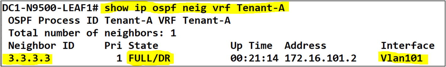
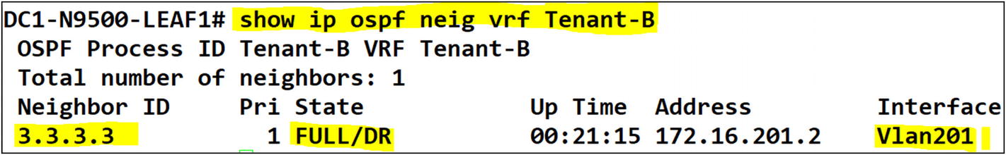
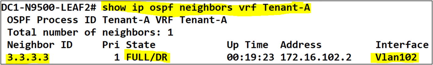
You can confirm that the tenants on both Leaf-01 and Leaf-02 have OSPF adjacency to the campus core.
Tenant-A
Tenant-B
Interface Redistribution to OSPF
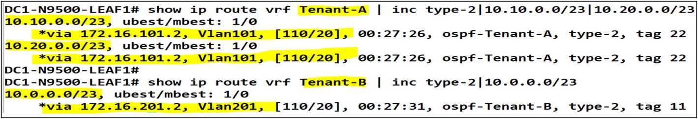
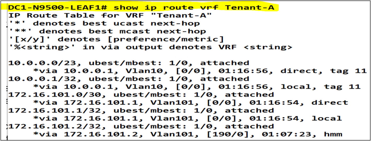
After executing the command “show ip route” we can confirm route redistribution into OSPF from the VXLAN fabric
Let’s confirm that the OSPF routes were built at the campus core switch from the VXLAN tenants.

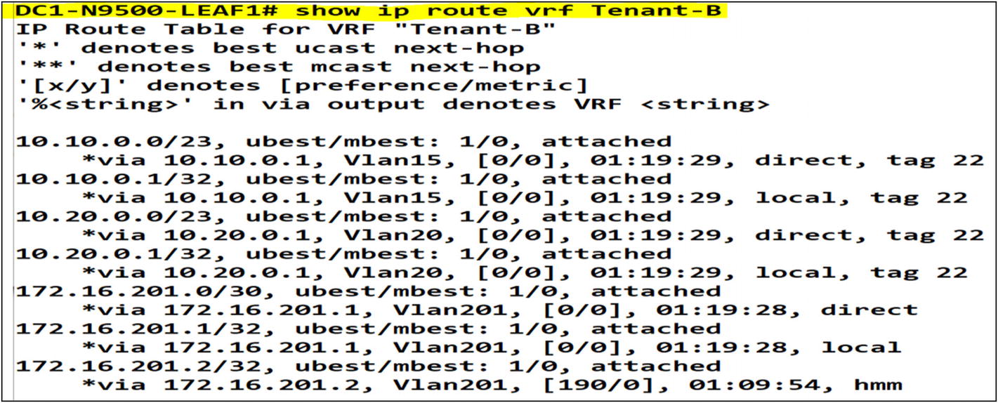
The next step is to filter any tenant-A and tenant-B routes from being advertised between each other by using the campus core. Let’s do some route filtering to accomplish that. Let’s look at Leaf-01 and Leaf-02. The routes from tenant-B are shown in tenant-A and vice versa.
The tenants can reach each other through the campus core switch. You need to avoid the tenant’s from seeing each other. The campus core network is only allowed to reach both tenants.
Let’s now add a route filter on Leaf-01 to filter incoming OSPF routes from tenants leaked in OSPF via the campus core. In summary, you create a route map with the “deny” action, and then match all the interfaces participating in the OSPF process.
OSPF Inbound Route Filtering Configuration
Without any route filtering in-place, Tenant-A and Tenant-B can reach each other via the campus core
Post-change result on Leaf-01 in tenant-A and tenant-B
After Applying route filtering we can confirm that Tenant-A and Tenant-B can’t reach each other
You no longer see routes advertised from the campus core to the tenants. You need to be aware of an active OSPF peering to both Leaf-01 and Leaf-02. To avoid any asymmetric routing issues, you must make sure that only one OSPF path is active at a time. How do you accomplish this? First, you need to identify which leaf becomes the active path for the campus core. I chose Leaf-01 to become the active OSPF path to the campus network. On the campus core side, you need to configure OSPF costing to influence routes to be preferred to either OSPF neighbor, in this case, Leaf-01. Do a simple OSPF costing configuration that is lower on the VLAN interfaces peering to Leaf-01. VLANs 101 and 201 are the designated OSPF peering interfaces between Leaf-01 and the campus core. You’ll see more of this in the next section.
Campus Core OSPF Cost Configuration

By setting up OSPF costing on any layer 3 interface participating in OSPF we can pin traffic to be preferred via a specific path
As you can see, there is one active route path via Leaf-01. Asymmetric routing issues are very common to face in VXLAN spines and leafs since the route paths are more elastic. I can route in many directions, but I still need to make sure that the traffic flow remains symmetric. In a nutshell, you send traffic one way, but the return traffic has a better path advertised via another leaf or so. This causes your asymmetric route flow issue.
In asymmetric routing issues, traffic does not return using the original path it came from. Due to many factors, mostly due to poor routing design and/or path selection
A symmetric route path between two tenants behind an external firewall
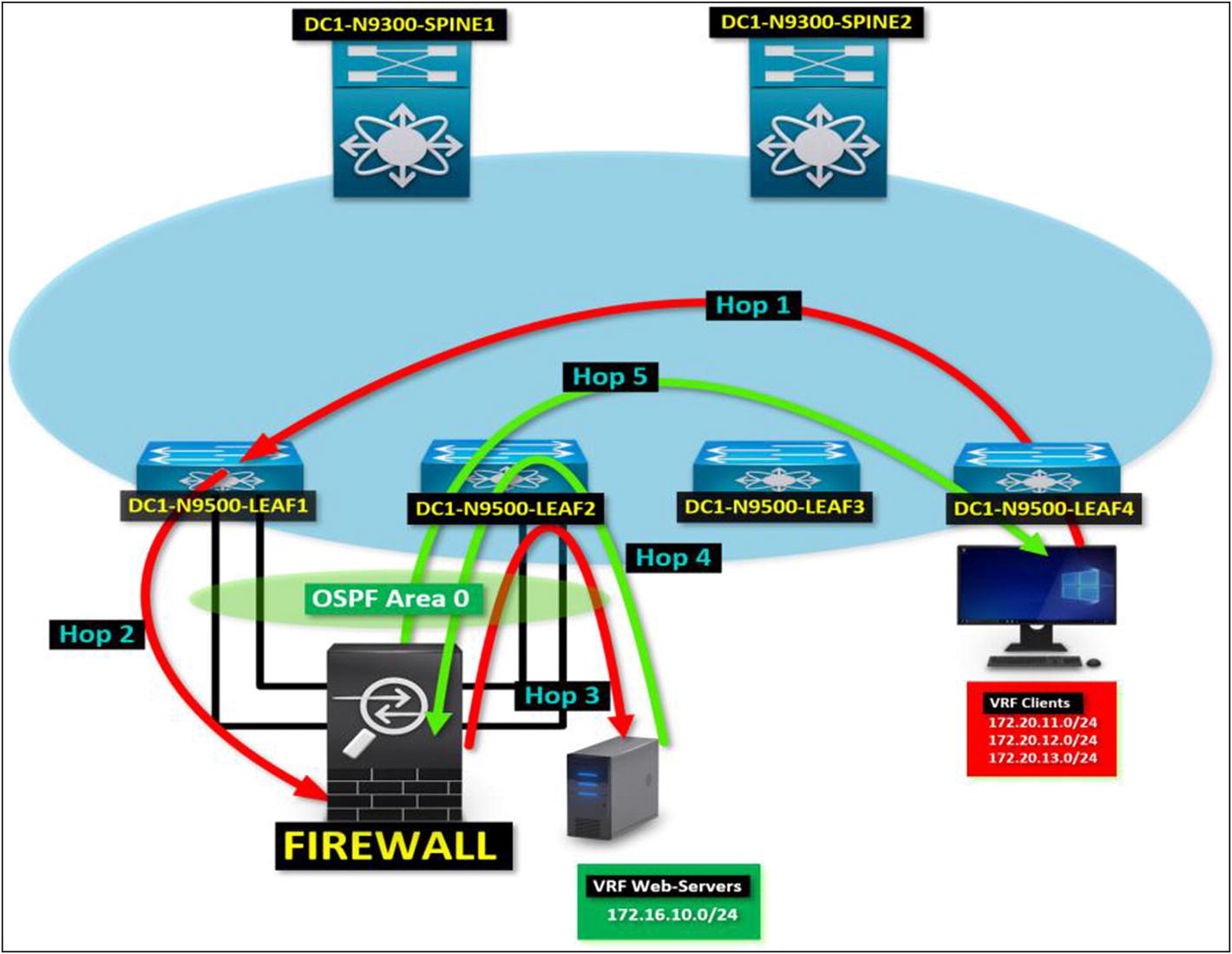
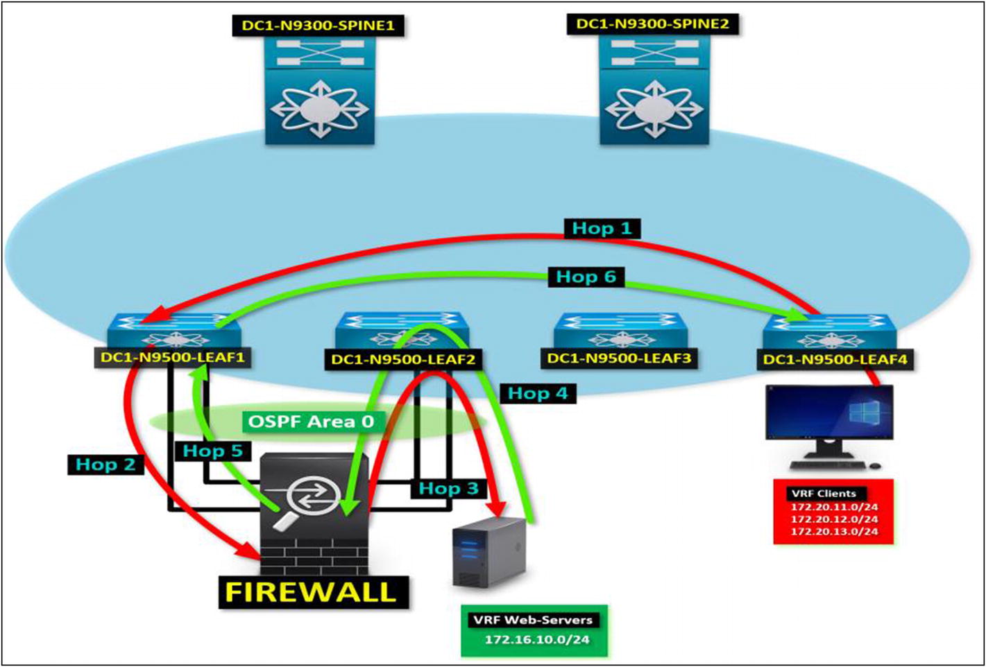
Asymmetric Route Issues in VXLAN BGP EVPN
Figure 5-11 describes each hop between a client tenant PC trying to communicate to the web servers tenant. By following each hop in the diagram, you see that the return traffic does not flow using the same path as the source request traffic from the client PC.
HOP 1: Client tenant PC sends a request to a web server. Leaf-04 sends the request to the VXLAN fabric. Traffic lands in Leaf-01 since it’s the preferred path to the web servers tenant via EVPN.
HOP 2: Leaf-01 sends the request to the external firewall since there’s an OSPF route advertised to the web server tenant.
HOP 3: Traffic leaves the firewall and lands in Leaf-02 since there’s no preferred path to the web server’s tenant. Leaf-02 sends the request to the web server’s tenant.
HOP 4: A server on the web server tenant replies to the request. Leaf-02 receives the request and forwards it to Leaf-04 instead of using the source path via the firewall peered in OSPF. The route to the client tenant is preferred over EVPN rather than OSPF.
HOP 5: At this point, the request fails to return due to an asymmetric route. The return traffic uses a different path due to OSPF equal-cost path between Leaf-01 and Leaf-02.
Symmetric Routing in VXLAN BGP EVPN
By confirming a symmetric route path, you guarantee that all requests and replies follow the same route path. In the diagram shown in Figure 5-12, you see the same scenario covered in the asymmetric route discussion. The difference is that the server traffic returns to the client using the same route path. How do you accomplish this? By making sure that you only configure a lower cost or distance in the dynamic route protocol, you are implementing so the traffic returns in the same direction it came from.
OSPF to BGP Route Redistribution
You can ensure that the traffic flows symmetrically by configuring OSPF costing or BGP distance (depending on which one you are using). Let’s configure and advertise the VRFs in a symmetric path. Let’s designate Leaf-01 to be the primary path to both VRFs. There is a network on the campus core that you want to reach. The address space is 10.100.10.0/24. All leafs should prefer Leaf-01 to reach this network. Leaf-02 should remain as a standby path to the destination of 10.100.10.0/24.
Routes Before Changes

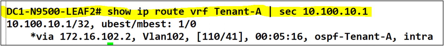
Tenant-A VRF on Leaf-02
In Leaf-02, the preferred path is still local to the campus core. You want to re-route the traffic from all leafs to prefer Leaf-01 then Leaf-01 forward to the campus core. You need to fix this by redistributing OSPF to BGP and tweaking the BGP distance, so it is preferred via Leaf-01 using EVPN type-5 route advertisements.

Modifying the iBGP distance to a value less than the default OSPF distance will make iBGP a preferred route over OSPF
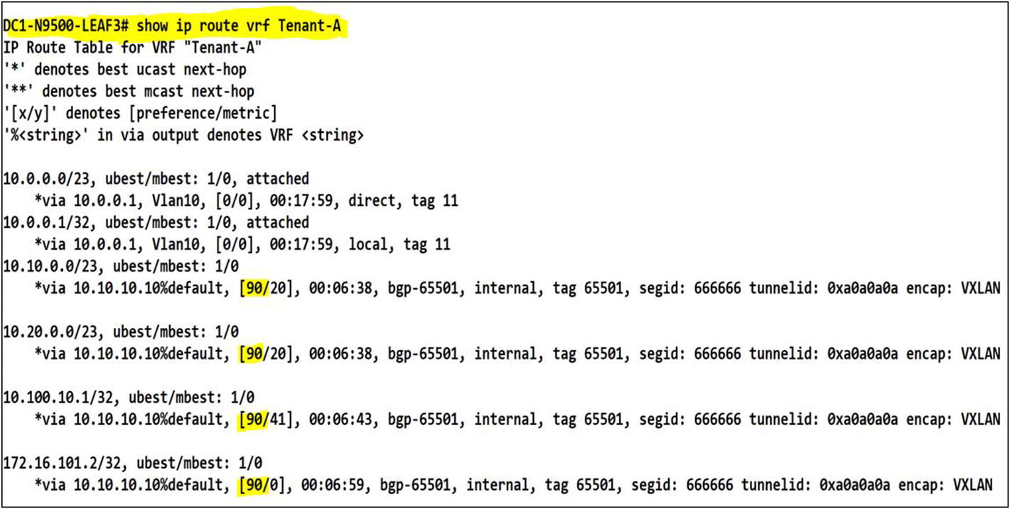
You can confirm that after applying the config under Leaf-03, the preference for iBGP routes has changed to 90. It provides a consistent route path through the VXLAN fabric
Dynamic Routing Protocols Under VRFs
Working with multitenant environments can bring a level of complexity that can make any network engineer frightened. It is why you must build every environment with consistency. Something as simple as your naming scheme can make a big difference when troubleshooting needs to happen. When you decide to peer VXLAN tenants to an external network using dynamic routing protocols like BGP, OSPF, EIGRP, or IS-IS, it can become quite a challenge to maintain consistency due to the number of extra configurations required to accomplish it.
Let’s say you have a tenant called Italy, and another tenant called France. They both run services and host applications using your VXLAN fabric as a data transport. You want to have both tenants completely isolated. That’s the sole reason for multitenancy. But also, all the relevant operational processes for each tenant should be isolated. Italy has requested to peer their tenant to an external MPLS network.
The service provider has provisioned a demarcation for this circuit, and it’s ready to peer to the tenant on the fabric. The CE (customer edge) router holding the MPLS boundary is going to exchange routes using eBGP. The Italy network needs to reach the Italy tenant. You need to peer them to their MPLS using eBGP.
On the other side, France needs to peer its remote offices to their tenants on the fabric using OSPF. France has provided a router awaiting to establish an OSPF neighbor relationship.
You need to fulfill the request from both customers and make sure that other tenants aren’t affected by this change. Remember its multitenant environment. You might have more than ten tenants using your fabric to run their hosted servers and applications. You don’t want to disrupt any other tenant. You need to plan the configurations ahead of time and validate them to be 100 percent confident during the implementation.
The first thing you do is gather the information provided by the customer. From this information, you can then build the configuration script to be applied to the border leafs. Please find the information provided by the customer to fulfill the request.
Tenant: Italy
MPLS L3VPN Router Interface: Gi0/1
MPLS L3VPN Router Interface IP: 145.11.24.25
MPLS L3VPN Router Interface Subnet 145.11.24.24/30
Italy MPLS eBGP AS: 43321
Italy VXLAN tenant BGP AS: 54423
- Networks announced from the MPLS cloud
172.21.10.0/24
172.21.20.0/24
172.21.30.0/24
You need to perform this configuration to receive the MPLS subnets on the Italy tenant VRF route table. The ISP informed that if you peer to them using private AS numbers, you won’t have an AS path or network reachability since those AS numbers are already in use in other locations.
A tenant to carrier connectivity diagram. The Italy MPLS peers to the border leaf
When you enable tenants with dynamic routing protocols, you need to designate either an existing routing process or create a new one per tenant. I prefer to work with independent routing processes because if there is an issue with one process, the other tenants aren’t impacted.
You already have BGP running for the VXLAN EVPN address family. You need to configure a BGP IPv4 address family for the Italy tenant. You need to add a unique BGP AS number for the Italy tenant. You need to use the same AS number to peer the tenants. That might be an issue since you don’t control what tenants assign to their BGP community from AS number perspective. Instead, allow them as or override the AS number, so you don’t have conflicts with any other possible BGP neighbor in the AS path using the same number.
Enabling BGP for a Tenant VRF
To enable BGP in a VRF, you need to add the VRF under the global BGP router process. Add the BGP neighbor and inform BGP to use an interface to source the hello message. You want to use the layer 3 interface that faces the MPLS router. Next, enable the AFI that you are working with. In our case, it is IPv4 unicast. With the information provided by the service provider, you need to establish adjacency to the MPLS router, which is connected to DC1-N9500-Leaf-01. Let’s use the information provided and perform the configurations.
Italy Tenant BGP Configuration on Leaf-01
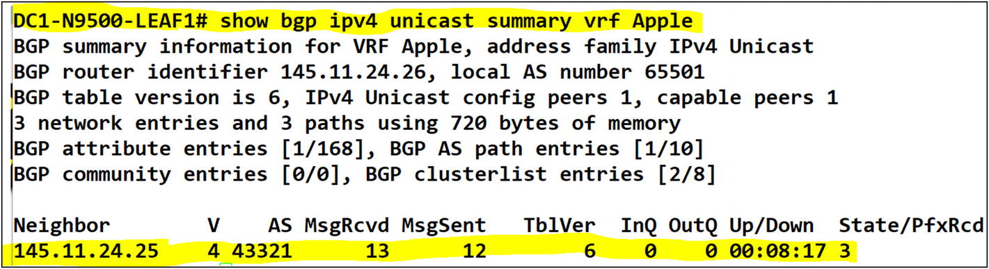
A BGP adjacency to an external router in the tenant has been confirmed
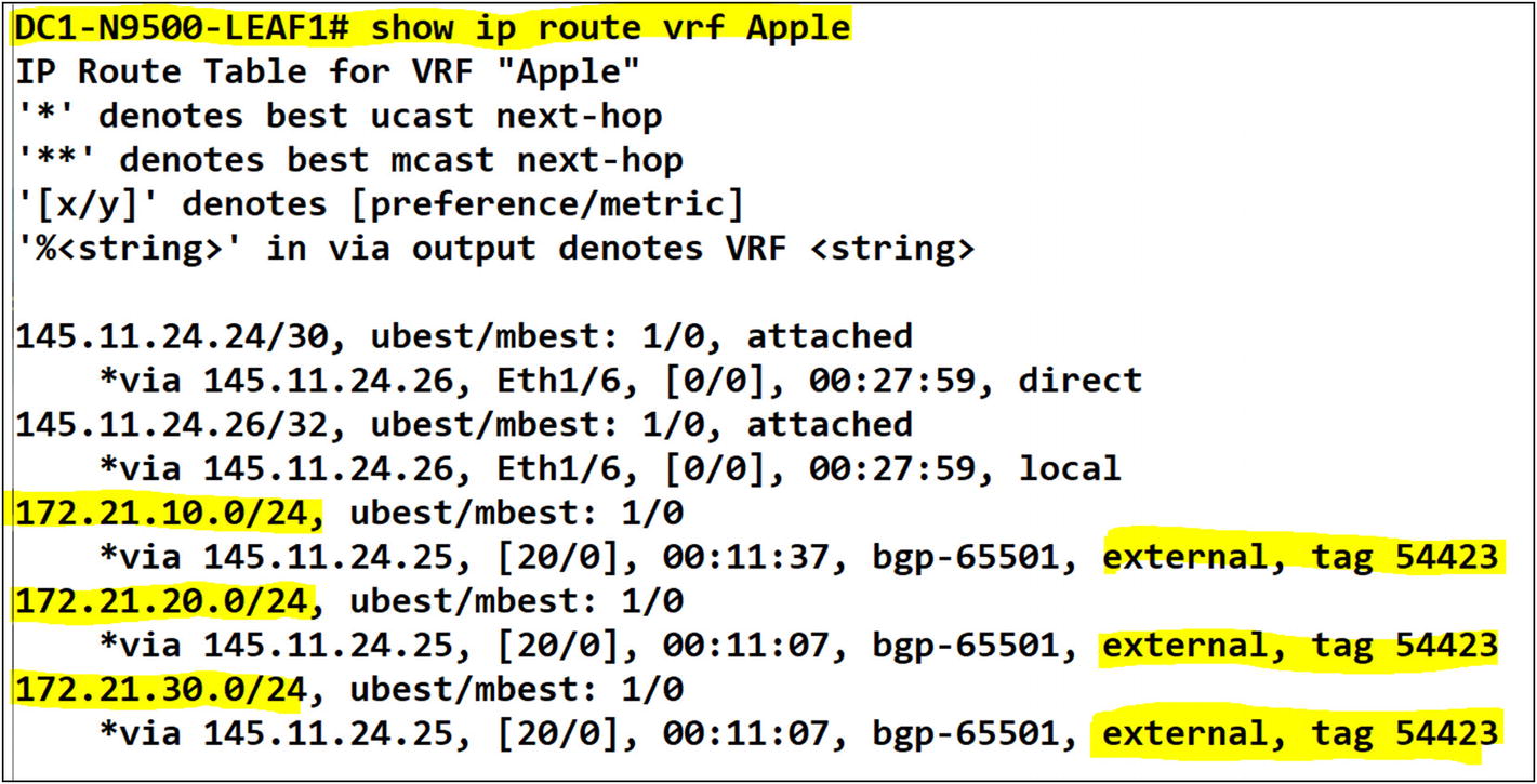
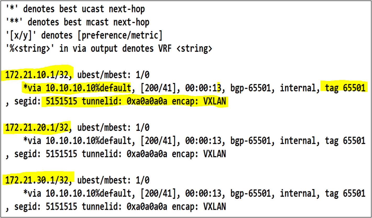
Routes have been learned in the tenant from the external MPLS router once BGP adjacency is established

The L3VNI interface in Leaf-03 is receiving the routes from Leaf-01 as EVPN route redistribution
Amazing. EVPN is doing its job. The MPLS networks are distributed in L3VNI to the other leafs. The next hop is the VTEP IP for Leaf-01.
Enabling OSPF for a Tenant VRF
Enabling OSPF for a tenant VRF is quite similar to BGP. The only difference with OSPF is that you can create a new OSPF router process and assign it to the tenant. In BGP, you only run a single BGP process. Once you create the OSPF process, you add the tenant VRF under it and configure your OSPF router ID. Here’s the catch. With BGP, you don’t have to redistribute the external networks so EVPN can re-advertise to all my leafs. In OSPF, you need to perform redistribution to announce the networks to the tenant in all leafs. Okay, let’s tackle the request to peer OSPF for the France tenant.
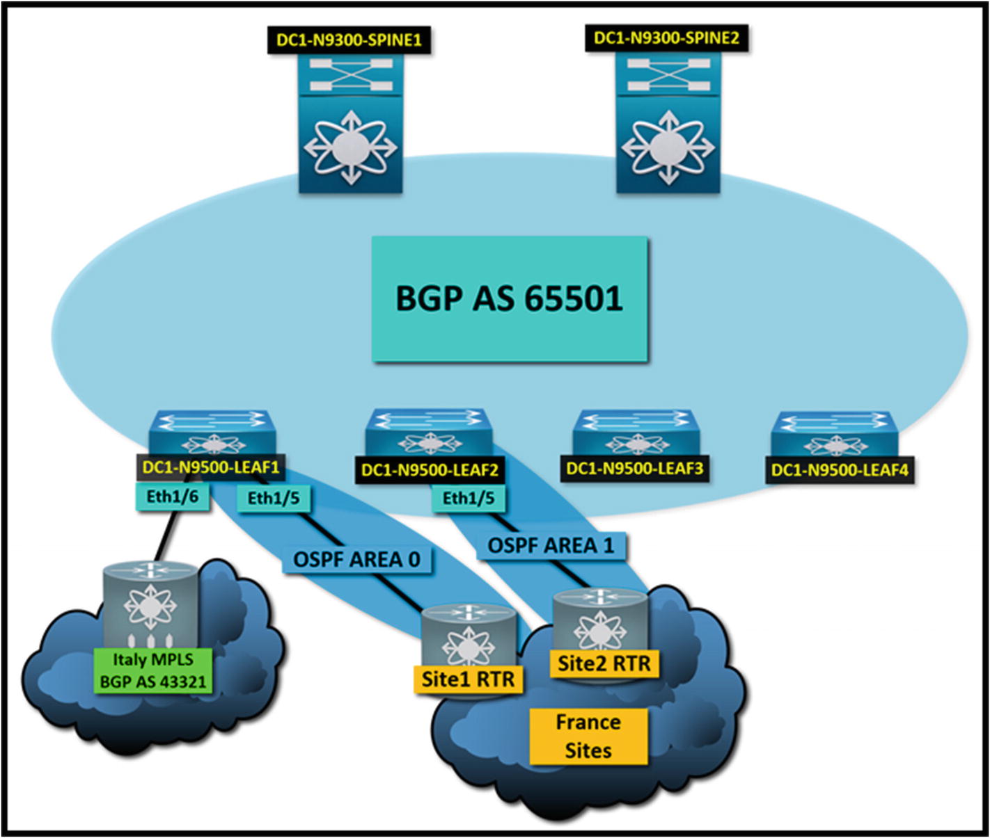
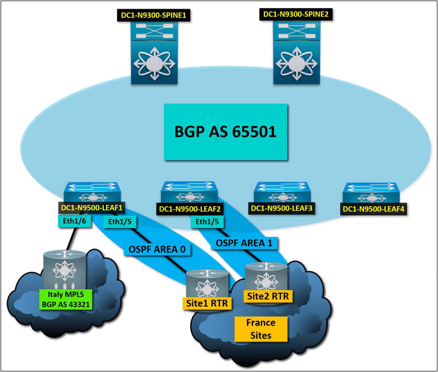
A multitenant VXLAN fabric peered with OSPF and BGP to external neighbors. The tenants are completely unaware of each other’s networks
Tenant: France
Site 1 – OSPF Area 0
Site 1 Router Interface IP 172.16.1.1
Site 1 Router Interface Subnet 172.16.1.0/30
Site 2 – OSPF Area 1
Site 2 Router Interface IP 172.16.2.1
Site 2 Router Interface Subnet 172.16.2.0/30
- Networks received via OSPF from site 1
172.21.10.0/24
172.21.20.0/24
172.21.30.0/24
- Networks received via OSPF from site 2
172.22.10.0/24
172.22.20.0/24
172.22.30.0/24
France Tenant OSPF Configuration on Leaf-01

Site 1 to France tenant OSPF neighbor in Leaf-01
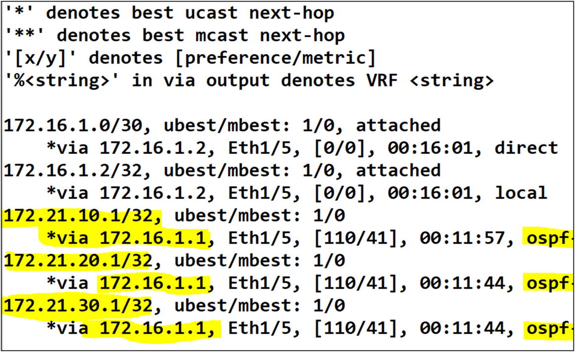
The routes in the France tenant are available via OSPF
The routes from the tenant France on Leaf-01 are advertised via EVPN to the rest of the fabric. Leaf-03 has received the routes via the France VRF L3VNI
France Tenant OSPF Configuration on Leaf-02

Site 2 to France tenant OSPF neighbor in Leaf-02

We can confirm that the OSPF routes in Leaf-02 are received from the site 2 router
Yes, routes are being received from site 2 to the France tenant. Finally, since you performed route redistribution from OSPF to BGP, let’s confirm that other leafs have received the routes via Leaf-02 L3VNI in EVPN.
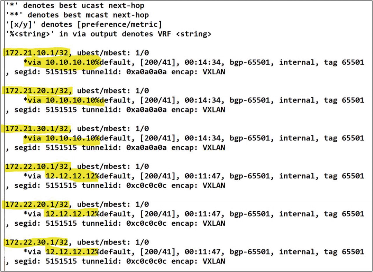
The routes learned via Leaf-02 are successfully advertised in EVPN to the other leafs in the fabric
Excellent! You can confirm that you have the routes from site 1 via EVPN to the L3VNI for Leaf-01 (10.10.10.10) and the routes from site 2 via EVPN to for Leaf-02’s L3VNI. The France tenant has end-to-end reachability to both sites across the entire VXLAN fabric. Success!
Default-Route Advertisement
How do you manage a default route in VXLAN BGP EVPN? In traditional campus networks, you usually have a border router or firewall connected to the edge of your network. When it comes to a spine-and-leaf topology, you usually connect this edge device between two leafs. You either statically assign a default route on those two leafs, or you get a default-route dynamically advertised from the edge device itself. But what about the other leafs. Do they also get it? No, unless you perform a default originate in the BGP IPv4 unicast address family on the tenant that receives it.
This section is about redistributing or re-advertising a default route in VXLAN BGP EVPN across the fabric for a tenant. Taking advantage of the previous exercise, let’s work with the same topology. Both France and Italy have requested to send all Internet-bound traffic via their remote networks. Italy would like to send from the tenant, traffic to the Internet via the MPLS circuit. France would like to send all Internet traffic to site 2. Let’s make sure that the default gateway is available across the Italy and France tenants’ fabric.

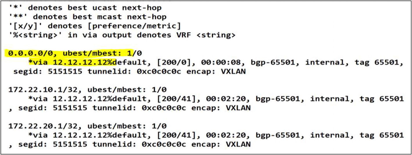
Italy tenant Leaf-01 route table
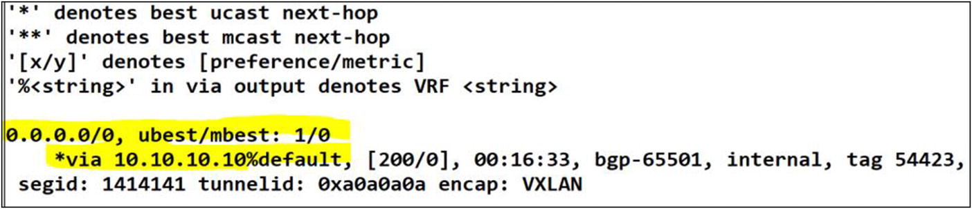
The default route has been learned from Leaf-01 in EVPN. The rest of the fabric will use this route as last resort thru the L3VNI
There are two important commands. The default-information originate command tells the routing protocol to advertise a default route in its process. By adding this command to a static default route, you tell the process to redistribute the default route via its neighbors. The second command is network 0.0.0.0/0. In BGP, redistributing a default route is much more than the default-originate command. BGP expects a network statement of the default route, which is 0.0.0.0/0; otherwise, it does not advertise it.

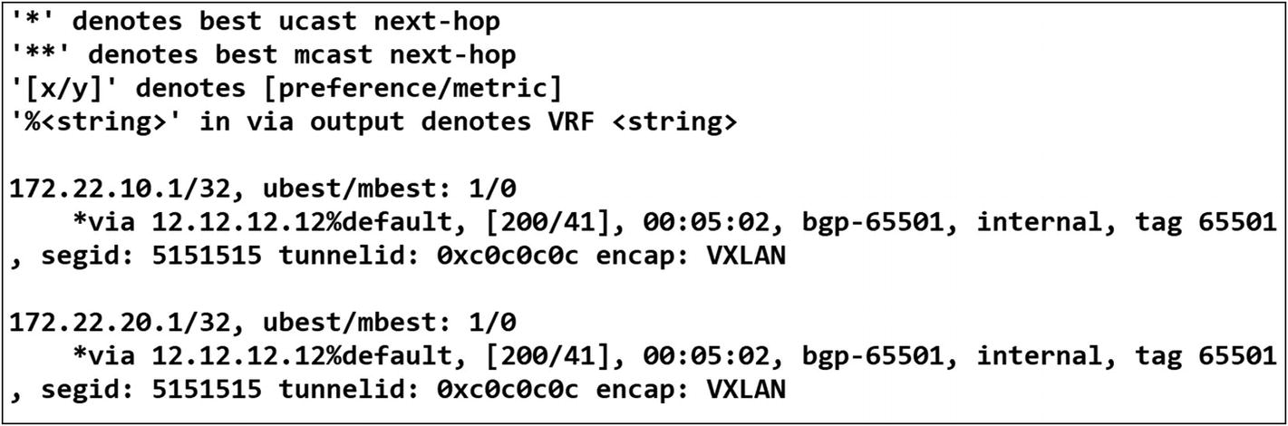
France tenant Leaf-02 route table
An additional configuration is required under BGP to readvertise a default route to all peer routers or in this case Leafs
After applying the configuration changes we can confirm a successful default route advertisement in BGP
Success! You have redistributed the default route from site 2 to all leafs in the France tenant. Mission accomplished!