You understand how VXLAN BGP EVPN works and how to configure all its major features. Let’s now explore available deployment designs. Each design is deployed to serve a specific operational mode in your VXLAN BGP EVPN fabric. When you reviewed the traditional three-tier architecture, you had the core layer, the distribution or aggregation layer, and finally, the access layer. From an L3 routing standpoint, the core layer performs this function.
In a VXLAN spine-and-leaf architecture, the leafs are performing all the tenant networks routing decisions and operations. However, VXLAN in BGP EVPN brings a more security-centric deployment design. There are single pod, multipod, and multisite VXLANs.
Another deployment design not commonly used but also available is head-end replication without spines. Spines allow expansion in the topology with an east to west direction and aggregate bandwidth among the leafs using ECMP. I already discussed the single pod VXLAN, which you have been configuring throughout this book—a single spine-and-leaf architecture. Now let’s discuss a multipod VXLAN.
Multipod VXLAN Architecture
A customer has two data centers. Data center 1 is located in Dallas, TX, while data center 2 is located in Los Angeles, CA. The customer is looking at the possibility of distributing compute workload between the two locations. If you need to perform virtual machine migrations from DC1 to DC2, you must present the VLANs from which the VMs communicate from. That means that you must somehow “stretch” from DC1 to DC2 every VLAN required to perform the virtual machine migrations. The customer approves the migration from the traditional three-tier architecture to VXLAN BGP EVPN.
You need to present the same VLANs from data center 1 to data center 2. By implementing a multisite VXLAN fabric, you create two identically configured VXLAN fabrics and share VXLAN advertisements to look like one big fabric.
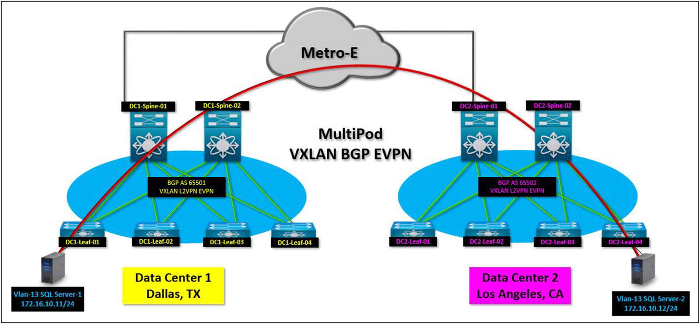
In terms of data center configuration differences, a multipod makes the architecture look like a single large fabric. Having DC1 as pod 1 and DC2 as pod 2, you can tailor VLANs exclusively for each site and have stretched or shared VLANs between the two pods because they operate like one single VXLAN fabric from an EVPN route input and output. How does the architecture look from a logical view? Please review the diagram shown in Figure 6-1.
Figure 6-1
A multipod VXLAN BGP EVPN fabric, two data centers with a stretched VLAN, and a server in DC1 on the same VLAN as a server in DC2. From a compute standpoint, it thinks it is on the same network
Note
The deployment options for a multipod vary. This diagram performs intra-data center connectivity or DCI (Data Center Interconnect) via the spines on both data centers. Another approach to perform the DCI is using transit leafs. The configurations to perform the DC-to-DC connectivity are reviewed next.
Multipod Integration
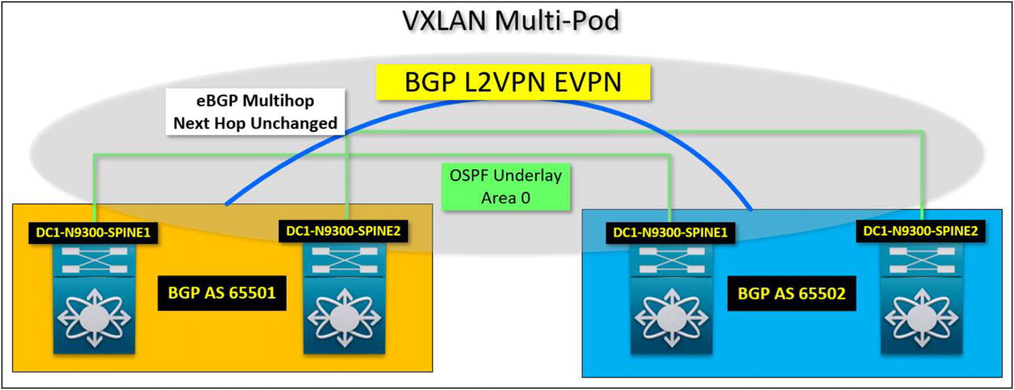
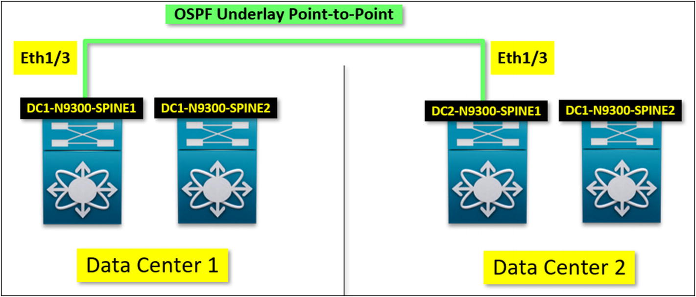
Multiple configuration options are available to enable a multifabric VXLAN multipod integration. The end goal is to build a logically stretched VXLAN fabric between geographically distant locations. When I say logically stretched VXLAN fabric, I mean that although there are two separate data centers with designated spines and leafs, you can configure them so that they operate like a single VXLAN fabric. This is known as a single data plane VXLAN architecture. There are multiple ways of performing the VXLAN fabric integration. You can peer both fabrics using the SPINE as the data center–to–data center hop. The spines advertise EVPN information in and out (see Figure 6-2).
Figure 6-2
A multipod VXLAN fabric configured using the spines as the transit between data centers
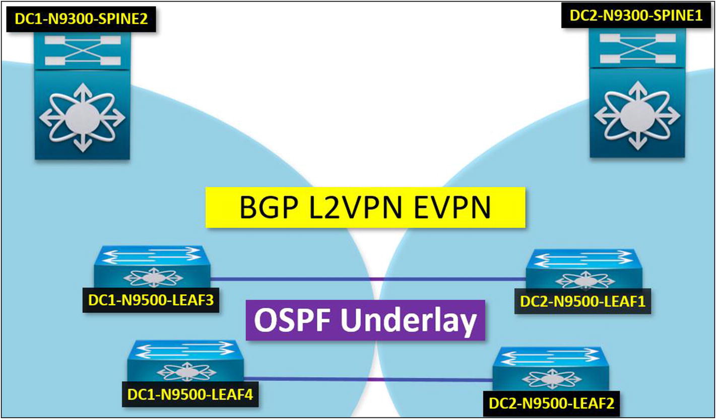
Another option is to use transit leafs for this purpose. Transit leafs cross-connect from one data center to another and perform EVPN redistribution between data centers. Both spine-to-spine and leaf-to-leaf are valid EVPN transits, depending on the fabric configurations if you designate the transit leafs.
It is configured similarly to the spine-to-spine. You need to configure an IGP for the underlay (OSPF) and the BGP control-plane EVPN, which peers between the two data centers. A spine-to-spine or a leaf-to-leaf option still performs the same EVPN route-target import and export between VRFs (see Figure 6-3).
Figure 6-3
A multipod VXLAN fabric design using transit leafs between data centers
Configuring a Multipod VXLAN Fabric
Let’s assume that you are deploying a multipod VXLAN fabric with two data centers. There is a single L2 circuit between DC1 and DC2. Let’s configure a spine-to-spine multipod EVPN Transit path. Please find the high-level steps and required configurations to enable the multipod transit.
Step 1: Configure the Underlay Link Between DC1 and DC2 on Spine-01
The underlay link is the physical point-to-point L2 circuit link between DC1 and DC2. You configure it like any other leaf to spine underlay link and enable IGP; in this case, OSPF (see Listings 6-1 and 6-2).
interface Ethernet1/3
description To_DC2-N9300-SPINE1-eth1/3
no switchport
mtu 9216
medium p2p
no ip redirects
ip address 100.200.0.1/30
no ipv6 redirects
ip ospf network point-to-point
ip router ospf Underlay area 0.0.0.0
ip pim sparse-mode
no shutdown
Listing 6-1
DC1-N9300-Spine-01
interface Ethernet1/3
description TO_DC1-N9300-SPINE1-eth1/3
no switchport
mtu 9216
medium p2p
no ip redirects
ip address 100.200.0.2/30
no ipv6 redirects
ip ospf network point-to-point
ip router ospf Underlay area 0.0.0.0
ip pim sparse-mode
no shutdown
Listing 6-2
DC2-N9300-Spine-01
A logical configuration diagram is shown in Figure 6-4.
Figure 6-4
Step 1 configuration enables the underlay between DC1 and DC2 to bring EVPN overlay between data centers
Step 2: Configure the BGP EVPN Multihop Peering Between Spines
You need to add the required configuration in the BGP process so DC1 and DC2 can bring EVPN adjacency up between the spines. You also need to make sure that the next hop IP doesn’t change as traffic passes the spine layer (see Listings 6-3 and 6-4).
! Create and configure the route-map to set ip next hop to unchanged. Apply this to both ! DC1 and DC2 Spine.
route-map DC1-to-DC2-MultiPod-VXLAN permit 10
set ip next-hop unchanged
! On DC1 Spine-01 configure the BGP neighbor for DC2 configs. Apply the route-map under the L2VPN EVPN AFI.
neighbor 2.0.0.100
remote-as 65502
update-source loopback0
ebgp-multihop 10
address-family ipv4 unicast
address-family l2vpn evpn
send-community
send-community extended
route-map DC1-to-DC2-MultiPod-VXLAN out
Listing 6-3
DC1-N9300-Spine-01
route-map DC1-to-DC2-MultiPod-VXLAN permit 10
set ip next-hop unchanged
neighbor 1.0.0.100
remote-as 65501
update-source loopback0
ebgp-multihop 10
address-family ipv4 unicast
address-family l2vpn evpn
send-community
send-community extended
route-map DC1-to-DC2-MultiPod-VXLAN out
Listing 6-4
DC2-N9300-Spine-01
Once the configuration has been completed, you can verify that the OSPF and BGP neighbors are established for DC1 Spine-01 and DC2 Spine-01.
After executing “show ip ospf neighbor” we can confirm proper underlay adjacency to DC1-N9300-Spine-01
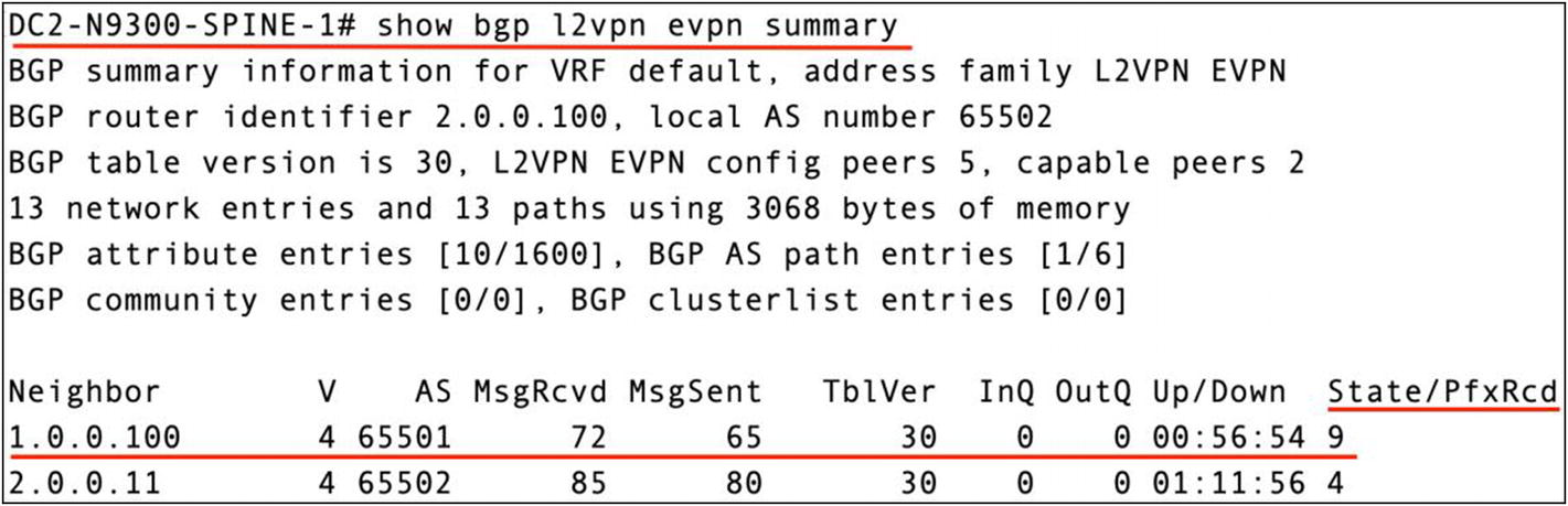
From DC2, there is OSPF adjacency to DC1 Spine-01. Let’s now verify if BGP EVPN peering is established with DC1 (see Figure 6-6).
Figure 6-6
We can confirm that evpn routes are being received from DC1-N9300-Spine-01
Based on the output, you can confirm that BGP EVPN adjacency to DC1 via Spine-01 was established. You have received EVPN prefixes from DC1. Now let’s confirm that there is NVE peering on Leaf-01 at both data centers (see Listing 6-5).
DC1-N9500-LEAF-1# show ip route
IP Route Table for VRF "default"
1.0.0.11/32, ubest/mbest: 2/0, attached
*via 1.0.0.11, Lo0, [0/0], 01:18:01, local
*via 1.0.0.11, Lo0, [0/0], 01:18:01, direct
1.0.0.100/32, ubest/mbest: 1/0
*via 1.11.100.1, Eth1/1, [110/41], 01:17:03, ospf-Underlay, intra
2.0.0.11/32, ubest/mbest: 1/0
*via 1.11.100.1, Eth1/1, [110/121], 01:03:15, ospf-Underlay, intra
2.0.0.100/32, ubest/mbest: 1/0
*via 1.11.100.1, Eth1/1, [110/81], 01:03:15, ospf-Underlay, intra
11.11.11.11/32, ubest/mbest: 2/0, attached
*via 11.11.11.11, Lo1, [0/0], 01:18:02, local
*via 11.11.11.11, Lo1, [0/0], 01:18:02, direct
21.21.21.21/32, ubest/mbest: 1/0
*via 2.0.0.100, [200/0], 01:03:12, bgp-65501, internal, tag 65502
DC1-N9500-LEAF-1# show nve peers
Interface Peer-IP State LearnType Uptime Router-Mac
We can confirm that the VXLAN NVE interface has peered to VTEP 21.21.21.21
There is NVE peering to DC2-N9500-Leaf-01 from DC1-N9500-Leaf-01. This confirms a successful BGP EVPN multipod communication.
EVPN L3VNI Routing in Multipod VXLAN
The multipod fabric is up. Data center 1 and data center 2 are fully integrated into a multipod architecture. Fifty percent of the multipod configuration is complete. Next, you need to stretch the tenants between data centers. If you have customer A in DC1, the same customer A should be available in DC2. For that, you must perform the route-target import and export.
If you want to refresh your mind with route-target import and export, please go to Chapter 3 and review the EVPN route-target section. In VXLAN with BGP EVPN, the L3VNI assigned to the VRF transport inter-VLAN traffic in the VXLAN fabric between leafs. The same L3VNI needs to be stretched between data centers. Let’s say you have tenant-A in DC1, and the information in Table 6-1 is the current information regarding its tenant network.
Table 6-1
VXLAN BGP EVPN Tenant-A Information to Configure on Both Data Centers
Name
Tenant-A
L3VNI
999999
L2VNI’s
100010, 100020
The first thing you must do to allow inter-VLAN routing between data centers is to import the L3VNI information in the BGP control plane, advertised in the respective VRF. Once this is in place, you should start getting EVPN route distribution through the entire multipod domain. Please refer to the diagram shown in Figure 6-7 for a logical view of this setup.
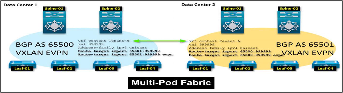
Figure 6-7
With route-target import and export we can import routes from the adjacent VXLAN pod and export our routes outbound to the adjacent VXLAN pod
EVPN L3VNI Multipod Configuration
Following the diagram shown in Figure 6-7, perform the required configurations to allow tenant-A to leverage both data centers in a multipod VXLAN (see Listing 6-6).
vrf context Tenant-A
vni 999999
Address-family ipv4 unicast
route-target import 65501:999999
route-target import 65501:999999 evpn
Listing 6-6
DC1 Configuration (All Leafs)
What is the configuration doing in DC1? If you look at the route-target value, there are two import actions. The first import action allows DC1 to import any IPv4 BGP AFI route from DC2 to DC1. The second route-target action is to import any EVPN type–based routes from DC2 to DC1. It means that any learned L2 address over EVPN, any route-redistribution in EVPN is advertised to the neighbor fabric or member pod in the multipod domain.
The value assigned to the RTs, 65501:999999, is arbitrary. In my case, I labeled it ASN:L3VNI to make it more consistent and easier to understand. ASN 65501 is the assigned iBGP autonomous system number to data center 2 and 999999 is the L3VNI value for tenant-A. Let’s configure DC2. As you should already know, you need to change the ASN value from 65501 to 65500 (DC1 ASN); everything else stays the same (see Listing 6-7).
vrf context Tenant-A
vni 999999
address-family ipv4 unicast
route-target import 65500:999999
route-target import 65500:999999 evpn
Listing 6-7
DC2 Configuration (All Leafs)
The diagram in Figure 6-8 illustrates what the configuration is doing traffic-wise.
Figure 6-8
A multipod L3VNI route-target import for both DC1 and DC2. By performing this configuration, you effectively import EVPN and BGP RTs between data centers
With the configuration in place, you can expect L3 information learned from either data center to be distributed to the remote data center. VXLAN operation would look like a single data center meaning that a leaf-to-leaf VXLAN traffic flow use NVE peering like it happens on a standalone VXLAN fabric.
Multisite VXLAN Architecture
A multisite VXLAN architecture is a cluster of VXLAN fabrics communicating specific traffic over an external IP network. Each fabric operates independently; however, they are configured to send or receive specific EVPN traffic. You use an external network (service provider) to establish communication among all sites. In a multisite architecture, independent VXLAN fabrics are sharing only specific traffic in the EVPN control plane.
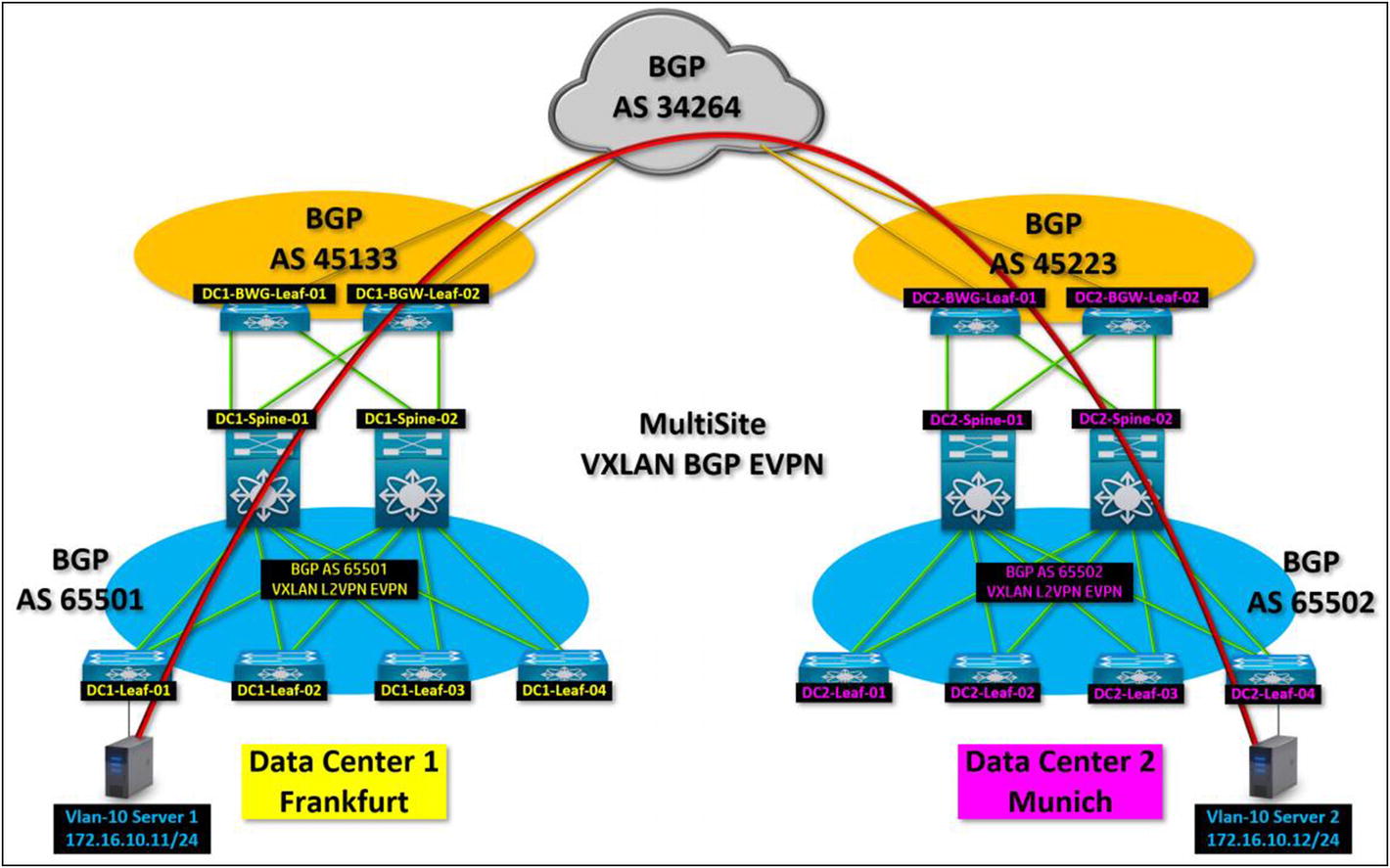
Let’s look at the diagram in Figure 6-9. There are two sites: site 1 is in Frankfurt, and site 2 is in Munich. They are communicating using a service provider cloud peered in eBGP.
Figure 6-9
In a multisite VXLAN BGP EVPN, you allow independent VXLAN fabrics to share specific traffic over a service provider network backbone. Sites are independent of each other
Knowing this information, on each VXLAN fabric, you add a device that allows the communication and the exchange from the external BGP (service provider) to the internal BGP (VXLAN fabric) and vice versa. It is called a border gateway leaf or BGW.
Border Gateway Leaf or BGW
BGW allows communication and adjacency between the local VXLAN fabric and the external transit network (service provider). EVPN traffic is forwarded to the transit IP network to reach its destination fabric using the border gateway. It also announces adjacent VXLAN fabrics from a participating site in the “cluster”. The local VXLAN fabric sees that it knows EVPN route types via an eBGP advertisement.
The cool thing about the BGW is that in BGP, it rewrites the ASN number as the traffic egresses to the backbone network. That means that if resources from the Frankfurt VXLAN fabric need to communicate to the VXLAN fabric in Munich as the traffic egresses, the BGW in Frankfurt advertises information changes from the internal 65501 ASN to an external 45133 ASN. Once the traffic reaches the remote site, the BGW at the remote site changes the eBGP ASN to an iBG P65502 ASN. It is fooling the remote VXLAN fabric into thinking that the source is locally present.
There are a couple of items to take into consideration. An additional configuration to the BGW links beside the underlay aspect is that you must enable a specific role to the uplinks participating in VXLAN. You must specify which link goes to the spines and which links go to the service provider. Another important item with a BGW is assigning an ID that is the designated site ID in the multisite cluster. Let’s say Frankfurt has site ID 100 and Munich has site ID 200.
The following configures the Frankfurt site ID on the Frankfurt BGW.
evpn multisite border-gateway 100
The following configures the Munich site ID on the Munich BGW.
evpn multisite border-gateway 200
EVPN Multisite Fabric Tracking
The evpn multisitefabric-tracking command informs the BGW that the interface ID facing the internal EVPN fabric. The border gateway then understands and applies the required action to the traffic that ingress or egresses from that interface. A multisite architecture provides the required information from the local fabric to the BGW to get it propagated to any other remote VXLAN fabric.
EVPN Multisite Data Center Interconnect Tracking
The evpn multisite dci-tracking command informs the BGW that the interface where it is applied is bound to the service provider network. DCI stands for data center interconnect, and that is it. It allows interconnection between data center fabrics located in remote sites. BGP uses that interface as a source to peer to the external service provider network. BGP source hello originate from this interface to the service provider or external network.
Ultimately, traffic incoming and outgoing from this interface is strictly eBGP. It has already been assigned the external BGP AS number from the local BGW. In Frankfurt, this would be from 65501 to 45133. It is great to talk about it, but it’s better to see the command in action in Figure 6-10.
Figure 6-10
Take a close look at this diagram. Interface Eth1/3 relates to the service provider router (external network). Interface Eth1/1 relates to DC1 Spine-01. You need to inform the BGP EVPN control plane which interface faces which network by applying the respective EVPN multisite configuration
interface Ethernet1/1
description TO_SPINE1
mtu 9216
medium p2p
ip address 100.0.40.1/31
ip ospf network point-to-point
ip router ospf 1 area 0.0.0.0
ip pim sparse-mode
evpn multisite fabric-tracking
no shutdown
Listing 6-8
The required configuration to establish a BGP peering between the BGW and the local VXLAN Fabric. Required for EVPN Multi-Site
In Listing 6-8, an interface from the BGW facing the local VXLAN spine must be configured with the evpn multisite fabric-tracking command. This command tells the BGP process on the BGW that it’s facing the local VXLAN fabric site and traffic to a remote site and from a remote site with traverse this link to the internal iBGP AS (the local AS number for the VXLAN fabric). Also, any outgoing traffic from the fabric is relayed to the BGW from the spine via this interface. The BGP peering source address to the spine from the BGW comes from this interface.
interface Ethernet1/3
description to_ServiceProvider
no switchport
ip address 10.111.111.1/30 tag 12345
evpn multisite dci-tracking
no shutdown
Listing 6-9
Sample configuration to establish a BGP peering from the BGW to the Service Provider
In Listing 6-9, an interface facing the service provider needs to be configured with the evpn multisite dci-tracking command, which informs the local fabric that it would be the path to reach any other VXLAN fabric site in the cluster. A tag must be assigned to the IP address because this is how you advertise the BGW peering IP to the remote site fabric.
Once both locations are reachable from a routing standpoint, the VXLAN overlay transit is established and allows both VXLAN sites to communicate. At this point, routing for VXLAN becomes purely eBGP between sites.
Border Gateway BGP Configuration
Let’s break down the BGP configurations on a border gateway. What can you expect from this configuration? There are a series of required configurations. I'm breaking down each one, describe it, and finally provide the full configuration.
Please review each one carefully.
A BGW needs a VTEP address which needs to be distributed to all other sites and allow the VXLAN overlay communication. Please review Listing 6-10.
!Frankfurt Data Center BGW-01
interface loopback100
description Frankfurt-VIP Multi-Site 1
ip address 10.1.111.111/32 tag 12345
ip router ospf 1 area 0.0.0.0
ip pim sparse-mode
!Munich Data Center BGW-01
interface loopback100
description Munich-VIP Multi-Site 1
ip address 20.1.111.111/32 tag 12345
ip router ospf 1 area 0.0.0.0
ip pim sparse-mode
Listing 6-10
BGW VXLAN VTEP Interface configurations
In Listing 6-10, a loopback interface is allocated for multisite EVPN peering configuration. Let’s assume that DC1-BGW-01 is in Frankfurt, and DC2-BGW-01 is in Munich. From a BGP configuration standpoint, you need to build the multisite peering using the IP of 10.1.111.111/32 (Frankfurt) and 20.1.111.111/32 (Munich). A VXLAN transport is established between both BGWs using the loopbacks previously configured.
You also assign a tag to the interface IP because that is how you redistribute an interface in BGP to advertise it to the remote data center. A route-map is configured to match this tag then used in BGP to reference the redistribution.
route-map REDIST-LOCAL permit 10
match tag 12345
Let’s breakdown the BGW BGP configuration (see Listing 6-11).
! Begin Configuration
Router bgp 45133
router-id 10.10.10.111
address-family ipv4 unicast
redistribute direct route-map REDIST-LOCAL
maximum-paths 4
Listing 6-11
Global BGP configuration on the BGW
In Listing 6-11, the first section of the configuration enables the IPv4 unicast AFI and advertises any local interface with the tag of 12345 assigned thanks to the route-map REDIST-LOCAL. You also specify the maximum BGP paths or hops you can take in the BGP path to send the information.
template peer TO_DC2_Multi-Site
remote-as 65502
update-source loopback0
ebgp-multihop 2
peer-type fabric-external
address-family l2vpn evpn
send-community
send-community extended
rewrite-evpn-rt-asn
Listing 6-12
A BGP template to peer the adjacent VXLAN site thru the BGWs
In Listing 6-12’s second section, I configured a series of peer templates. The beauty of using templates is that instead of writing the same attributes for each neighbor that you intend to peer over and over. You write the template and assign it to each neighbor. This template allows the multisite peering from the BGW to the remote site.
You specify a maximum of two hops between BGP neighbors to reach the destination. You also identify on the template that the neighbor you intend to peer to would be an external fabric peer in the multisite cluster. Under the L2VPN EVPN AFI, you enable the magic command that rewrites the RT for the ASN as it traverses the BGW.
template peer TO_SPINES
remote-as 65501
update-source loopback0
ebgp-multihop 10
address-family ipv4 unicast
send-community
send-community extended
address-family l2vpn evpn
send-community
send-community extended
Listing 6-13
BGP template to peer the BGW’s to the Spines
In Listing 6-13, I created a second template. This template has all the configuration required to peer the neighbor spines to the BGW. With templates, you significantly lower the amount of configuration syntax, making the BGP configuration cleaner.
neighbor 10.111.111.2
remote-as 34264
address-family ipv4 unicast
neighbor 10.222.111.2
remote-as 34264
address-family ipv4 unicast
Listing 6-14
A BGP configuration template to peer the remote spines to the BGWs
In Listing 6-14, the neighbors specified in this configuration are my service provider routers with AS 34264. I enabled the AFI for IPv4 unicast in BGP. This is needed to advertise to the remote fabric my BGW loopback (loopback100).
neighbor 20.20.20.111
inherit peer TO_DC2_Multi-Site
neighbor 20.20.20.222
inherit peer TO_DC2_Multi-Site
Listing 6-15
Sample configuration to apply a peering template to a BGP neighbor
In Listing 6-15, the configuration allows my local BGW to peer to the remote site BGWs. As you can see, I now associate my previously configured template applying all relevant configuration parameters.
neighbor 100.100.100.100
inherit peer TO_SPINES
neighbor 200.200.200.200
inherit peer TO_SPINES
Listing 6-16
Sample configuration to apply a peering template to a BGP neighbor
In Listing 6-16, the configuration allows the BGW to peer to the local spines. Also, I associate the template I configured with all required configurations to peer BGP with the local spines.
evpn multisite border-gateway 100
interface nve1
no shutdown
host-reachability protocol bgp
source-interface loopback1
multisite border-gateway interface loopback100
member vni 10010
suppress-arp
multisite ingress-replication
mcast-group 225.1.1.10
member vni 10011-10020
suppress-arp
mcast-group 225.1.1.111
member vni 11111 associate-vrf
router bgp 45133
router-id 10.10.10.111
address-family ipv4 unicast
redistribute direct route-map REDIST-LOCAL
maximum-paths 4
template peer TO_DC2_Multi-Site
remote-as 65502
update-source loopback0
ebgp-multihop 2
peer-type fabric-external
address-family l2vpn evpn
send-community
send-community extended
rewrite-evpn-rt-asn
template peer TO_SPINES
remote-as 65501
update-source loopback0
ebgp-multihop 2
address-family ipv4 unicast
send-community
send-community extended
address-family l2vpn evpn
send-community
send-community extended
neighbor 10.111.111.2
remote-as 34264
address-family ipv4 unicast
neighbor 10.222.111.2
remote-as 34264
address-family ipv4 unicast
neighbor 20.20.20.111
inherit peer TO_DC2_Multi-Site
neighbor 20.20.20.222
inherit peer TO_DC2_Multi-Site
neighbor 100.100.100.100
inherit peer TO_SPINES
neighbor 200.200.200.200
inherit peer TO_SPINES
Listing 6-17
Full BGP BGW Configuration
Validate Multisite VXLAN Communication
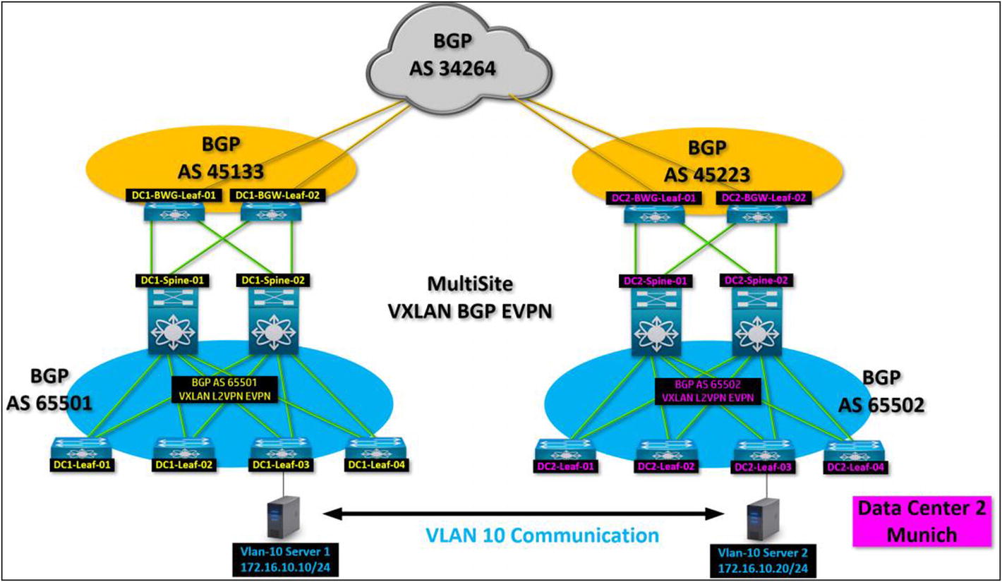
Here’s a new scenario. There are two servers on VLAN 10. The Frankfurt server’s IP is 172.16.10.10 IP. The Munich server’s IP is 172.16.10.20. How do you verify that both fabrics have learned the corresponding MAC and IP information from those two servers and the servers can communicate? Let’s look at Figure 6-11.
Figure 6-11
A Multisite VXLAN Architecture
Next, let’s look at the Frankfurt border gateway DC1-BGW-01.
We can confirm if we are receiving any EVPN routes by invoking the “show bgp l2vpn evpn”
Listing 6-19
Output of all BGP EVPN type routes learned on a particular leaf
Listing 6-9 confirms the MAC address or type-2 EVPN advertisement from the remote BGW in Munich (20.2.222.22) in the L2VNI. It also confirms the 172.16.10.20 location from Frankfurt’s BGW pointing to Munich.
show bgp l2vpn evpn summary
DC1-BGW1# show bgp l2vpn evpn summary
BGP summary information for VRF default, address family L2VPN EVPN
BGP router identifier 10.10.10.111, local AS number 65500
BGP table version is 41, L2VPN EVPN config peers 4, capable peers 2
21 network entries and 21 paths using 4080 bytes of memory
BGP attribute entries [21/3528], BGP AS path entries [1/6]
BGP community entries [0/0], BGP clusterlist entries [0/0]
Neighbor V AS MsgRcvd MsgSent TblVer InQ OutQ Up/Down State/PfxRcd
20.20.20.111 4 65502 0 0 0 0 0 00:32:46 Idle
20.20.20.222 4 65502 54 39 41 0 0 00:31:08 7
100.100.100.100 4 65500 42 40 41 0 0 00:32:23 0
200.200.200.200 4 65500 0 0 0 0 0 00:32:46 Idle
Neighbor T AS PfxRcd Type-2 Type-3 Type-4 Type-5
20.20.20.111 E 65502 Idle 0 0 0 0
20.20.20.222 E 65502 7 6 1 0 0
100.100.100.100 I 65500 0 0 0 0 0
200.200.200.200 I 65500 Idle 0 0 0 0
Listing 6-20
Lets confirm how many active BGP EVPN neighbor border gateways we can see from DC1-BGW1
Listing 6-21
As you can see on the diagram we are currently exchanging EVPN routes/prefixes with 20.20.20.222 which is the second border gateway at DC2 over EVPN
Listing 6-10 confirms with show bgp l2vpn evpn summary output that you are successfully peered in EVPN from Frankfurt’s BGW to Munich BGW with IP 20.20.20.222
You are receiving type-2 and type-3 routes in EVPN, which is a very good sign that the configuration is working. You should see a similar output for the Munich BGW.
DC2-BGW2# show bgp l2vpn evpn summary
BGP summary information for VRF default, address family L2VPN EVPN
BGP router identifier 20.20.20.222, local AS number 65502
BGP table version is 41, L2VPN EVPN config peers 4, capable peers 2
21 network entries and 21 paths using 4080 bytes of memory
BGP attribute entries [21/3528], BGP AS path entries [1/6]
BGP community entries [0/0], BGP clusterlist entries [1/4]
Neighbor V AS MsgRcvd MsgSent TblVer InQ OutQ Up/Down State/PfxRcd
10.10.10.111 4 65500 55 43 41 0 0 00:34:39 5
10.10.10.222 4 65500 0 0 0 0 0 00:36:19 Idle
101.101.101.101 4 65502 0 0 0 0 0 00:36:19 Idle
201.201.201.201 4 65502 50 44 41 0 0 00:35:37 2
Neighbor T AS PfxRcd Type-2 Type-3 Type-4 Type-5
10.10.10.111 E 65500 5 4 1 0 0
10.10.10.222 E 65500 Idle 0 0 0 0
101.101.101.101 I 65502 Idle 0 0 0 0
201.201.201.201 I 65502 2 2 0 0 0
Listing 6-22
BGP EVPN border gateway adjacency from DC2 to DC1
Listing 6-11 confirms the same information in Munich. You learn EVPN type-2 and type-3 routes from the BGW in Frankfurt (10.10.10.111).
Let’s do the final verification in DC1-Leaf-03 in Frankfurt to confirm that you see the BGP EVPN prefixes from Munich. You should see the advertised 172.16.10.20 server in the Frankfurt tenant-VRF.
We can now got confirmation that we have received EVPN type-5 routes on DC1-Leaf-03
In Listing 6-23, the EVPN route from Munich advertises the 172.16.10.20 server IP in the Frankfurt leaf for tenant-1. You can see the locally learned Frankfurt server’s 172.16.10.10 IP.
Ingress Replication VXLAN Architecture
In VXLAN BGP EVPN, you leverage multicast to announce the BUM traffic information. This is performed by a rendezvous point (RP) configured with a routing device that participates in the VXLAN fabric underlay. When designing a VXLAN architecture, you need to analyze your overall fabric configuration and leaf capability requirements.
Simpler fabric designs are also available for deployment. Maybe you don’t need a large-scale spine-and-leaf architecture. Your environment could be handled with only four leafs, considering that port density requirements aren’t critical and that there’s no expectation for any future growth. With this in mind, you can deploy a VXLAN fabric on a much smaller scale.
One simpler/smaller architecture can be configured with head-end replication (HER), also known as ingress replication (IR). IR handles BUM traffic announcements using unicast instead of multicast, which means that the underlay multicast configuration is not performed. Multicast-specific architecture configurations such as VNI multicast groups and rendezvous points are removed, making the underlay configuration much simpler. It sounds good from an implementation standpoint, but there’s a drawback and a reason why it may not be suited for your environment.
Announcing BUM using unicast requires more hardware resources. Every time you advertise to BUM traffic, it requires a unicast message to do so. Every leaf needs to communicate its BUM traffic information to all neighbor leafs. Leaf-01 sends the BUM to Leaf-02, Leaf-03, and Leaf-04 rather than having a multicast group and a single announcement performed since every leaf listens to the group, gets the information, and responds within vs a unicast message performed by all leafs every time it needs to send the BUM announcement.
A VXLAN BGP EVPN Fabric Without Spines?
VXLAN BGP EVPN without spines is possible with ingress replication (IR) since it removes the need for multicast. A rendezvous point (RP) configured at the spine layer is no longer needed. The need for east-west fabric expansion is no longer needed, so the spines that allowed the expansion benefit are not needed.
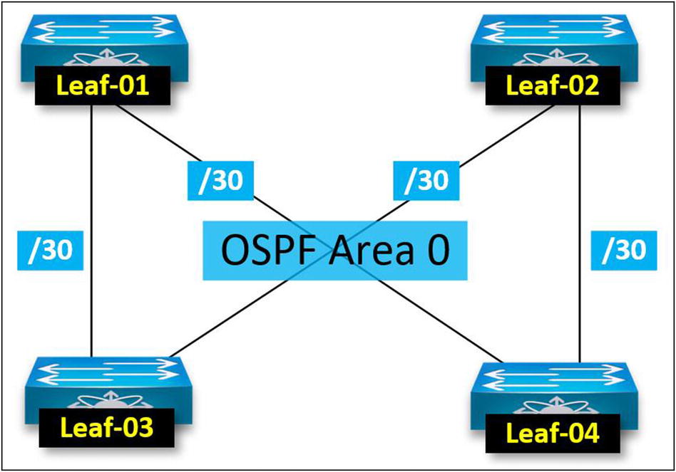
You still take advantage of ECMP in the underlay IGP and VXLAN overlay since you can use dual home leafs between each other. For example, Leaf-01 can be homed to Leaf-03 and Leaf-04. Leaf-03 can be homed to Leaf-01 and Leaf-02. Connection redundancy is still present (N+1). With an IR design, you connect the leafs underlay links together (see Figure 6-12).
Figure 6-12
IR/HER VXLAN BGP EVPN architecture without spines. Underlay links are configured the same way as spine-and-leaf architecture but without the need for multicast. Enabled multicast is not required on the interface configuration
A BGP EVPN operation in IR/HER works similarly to multicast in spine-and-leaf. The only difference is that you no longer route-reflect EVPN on the spines, so the NVE peers between leafs. You enable NVE peering between the VTEPs (leafs). The BGP EVPN route path is leaf-to-leaf at this point, so no transit via any spines. VTEP NVE peering happens the same way as the spine-and-leaf model, Leaf-01 NVE interface peers to all neighbor leafs (see Figure 6-13).
Figure 6-13
BGP EVPN communicates similarly without spines in the fabric. The VTEPs peer each other using the adjacency established in the IGP. VXLAN traffic path remains the same, leaf to leaf
Note
IR/HER is also supported in a spine-and-leaf architecture. The spines still reflect the BGP EVPN AFI traffic to the leafs. The environment remains multicast-independent from an underlay standpoint.
Configuring IR/HER
With IR/HER, the leaf configurations are significantly simpler than configuring it with underlay multicast. The only configuration needed in IR/HER is performed under the NVE interface (see Listing 6-24).
int nve 1
source-interface lo0
host-reachability protocol bgp
member vni 10010
suppress-arp
ingress-replication protocol bgp
Listing 6-24
Enabling ingress-replication (HER) for a particular VNI, in this case 10010
In Listing 6-24, the only configuration required with IR/HER is to specify under the NVE interface that you use IR to perform the BUM messages for a member VNI with unicast rather than multicast groups.
Let me provide you a sample leaf configuration template using IR/HER. Please review the configuration script and compare it with a multicast-enabled underlay configuration so you can spot the differences. It is quite noticeable.
A sample ingress replication configuration leaf template
IR/HER VXLAN Fabric Without Spines
Let's perform some show commands to see how an IR/HER fabric performs. You should see the same results as with a multicast-enabled underlay fabric. Confirm which OSPF neighbors have established adjacency. You should not see any other device but leafs. Also, confirm that you see EVPN routes advertised and the MACs learned. Finally, make sure multicast is not running on the environment.
BGP summary information for VRF default, address family L2VPN EVPN
BGP router identifier 1.0.0.10, local AS number 65501
BGP table version is 32, L2VPN EVPN config peers 3, capable peers 3
14 network entries and 14 paths using 2640 bytes of memory
BGP attribute entries [11/1848], BGP AS path entries [0/0]
BGP community entries [0/0], BGP clusterlist entries [0/0]
Neighbor V AS MsgRcvd MsgSent TblVer InQ OutQ Up/Down State/PfxRcd
1.0.0.20 4 65501 61 59 32 0 0 00:50:07 1
1.0.0.30 4 65501 61 60 32 0 0 00:50:20 1
1.0.0.40 4 65501 53 48 32 0 0 00:38:49 3
Listing 6-26
By performing a “show bgp l2vpn evpn summary” from DC1-Leaf-01 we have confirmed that we have the other three leaves adjacent from a BGP EVPN peering standpoint
BGP L2VPN EVPN Neighbors are active and established.
DC1-LEAF-01# show nve peers
Interface Peer-IP State LearnType Uptime Router-Mac
VXLAN NVE peering is established from DC1-LEAF-01 to all other leafs.
OSPF status.
DC1-LEAF-01# show ip ospf neig
OSPF Process ID Underlay VRF default
Total number of neighbors: 2
Neighbor ID Pri State Up Time Address Interface
1.0.0.30 1 FULL/ - 01:09:06 10.30.0.2 Eth1/1
1.0.0.40 1 FULL/ - 00:57:31 10.40.0.2 Eth1/2
The OSPF status is active, DC1-LEAF-01 neighbors are LEAF-03 and LEAF-04. This confirms that the fabric does not have any spines participating in OSPF. Leafs are peering to leafs.