
6
Solution Design and Functional Document
This chapter will cover different ways to identify functional and non-functional requirements using process flows during the solution design phase of the project. We will cover aspects where the designed solution is flexible, maintainable, and scalable. We will also cover data-related requirements such as the volume of data, legacy data, and data transformations. We will take all these aspects of the solution and document all the steps within a process flow in the functional document.
In this chapter, we will cover the following topics:
- Understanding solution design
- Identifying functional requirements
- Identifying non-functional requirements
- Reviewing data conversion requirements
- Understanding the functional requirements matrix
- Developing the function document
- Practical tips for success
By the end of this chapter, you will have gained firsthand experience with solution design aspects and in elaborating functional and non-functional requirements. You will have also learned to effectively analyze and enhance process flows and be able to identify and finish documenting the functional design document.
Understanding solution design
In the previous chapter, we successfully documented the business requirements in our business requirements document (BRD) in business-understandable and system-agnostic terminology. Solution design enables us to dissect high-level business requirements. In this section, we are going to refine them and deconstruct them into more granular details in the form of functional and non-functional requirements. These detailed requirements are documented in the solution design document, which is also called a functional design document (FDD) or a functional specification document (FSD).
The following steps define the hierarchy of the flow of requirements:
- We start with a prioritized list of business (stakeholder) requirements.
- We further slice the requirements and add a little bit more clarity and details, and capture the requirements in a BRD. The approved BRD will contain our baseline requirements that have been approved and agreed upon by the stakeholders and project team members.
- The next step is for us to add more granularity to the requirements to make sure we define requirements that the software system can fulfill. This is done via architectural design to define conceptual feasibility and then solution design to define feasible requirements.
- Solution design requirements are documented in FD/FDD/FSD in technical terms so that the technical team can use this document to create a usable solution encompassing functional features and other system-related features. This allows the user to reliably and efficiently use the software features and functions.
There are two levels of solution design processes:
- High-level design, also called the solution architecture design process
- Low-level design, also called the component-level design process
The solution architecture design process is also known as a high-level solution design and provides potential and alternative solutions. This is when we decide which technology to utilize; for example, what type of middleware do we use for our interfaces? Is it on-premise or in the cloud?
We arrange all the functions in a logical sequence so that we can trace the process from start to finish. This process is iterative and the decomposition continues until we reach a stage where the solution has been analyzed, understood, defined, and agreed upon. At this point, the system is architecturally defined with all the potential requirements identified, which are verifiable, feasible, and consistent. We do our best within the constraints and project timelines, run this through a few iterations, and freeze the version and baseline. There may be a few open-ended functions that are not on the critical path, which can be added as assumptions and need to be determined soon.
Note
Always develop multiple conceptual flows; we need at least two alternative paths. This needs to be done at the same time we create the primary flow. We always need to do a what-if for every step in the flow. Each path should achieve the desired goal or objective.
The component-level design process is also known as a low-level solution design. The high-level BRD requirements are logically decomposed into the lowest-level functions. Each function is then analyzed for technical feasibility and technical aspects of the requirements such as availability, performance, and reliability to achieve an optimal solution. We use a logical decomposition process to improve our understanding of our technical requirements and their dependencies and relationships.
Solution design always starts with the conceptual flow that we created during the requirements gathering phase. We take this conceptual diagram and elaborate on it, along with the BRD requirements. During the initial iteration of solution design, we include and collaborate with the architects – the enterprise and solution domain, business analysts, technical leads, lead developers, and SMEs. We can use many tools to visualize and elaborate the conceptual flows into more granular steps in technical terms. During this phase, we consider the technology that shall be used while developing the solution design. An experienced domain expert will be able to identify most of the non-functional requirements and confirm or clarify the feasibility of the functional steps in the flow diagrams. We will discuss this in more depth by covering real-world scenarios. There, we will identify the hidden functional and non-functional requirements.
Note
There is no such thing as a perfect solution. With constraints on time, resources, and technology, the best we can do is come up with an optimal solution. Based on the complexity and criticality, we can use process flows and prototype techniques to gain more understanding and keep refining the solution design until we reach an optimal solution. This optimal solution approach has to be agreed upon and approved by key stakeholders. During development, design thinking helps us evaluate our development work, fine-tune the solutions, and make it even more optimal and ready for implementation by our technical team.
During the solution design phase, we identify functional and non-functional process flow steps. In the next section, I will walk you through a simplified practical real-life process flow and discuss how to identify new process steps.
Identifying functional requirements
We reviewed functional requirements at a high level in the previous chapter. We analyze these requirements from a technical perspective during the solution design phase and capture hidden and elusive requirements. These requirements are functional but not obvious to business users, without which we cannot enable the desired functionality effectively – for example, reducing redundant steps by automating certain processes.
Let’s take a look at a realistic scenario. I have simplified very complex scenarios for the sake of clarity and understanding.
In terms of the BRD requirements, the following are the key ones; they are interdependent:
- Users shall be able to create customer records and be able to see products entitled by the customer based on the customer attributes industry, segmentation, and route to market
- Users shall be able to adjust entitled products by adding or removing certain products from the customer record
- Users shall be able to create opportunities and see all entitled products that have been added to the opportunity record from the customer record
The process flow is for opportunity product alignment, but we have to review these three business requirements as they are interdependent. If we don’t align the products to the account record accurately, automatically adding products to the opportunity is not possible.
Take a look at the following diagram:
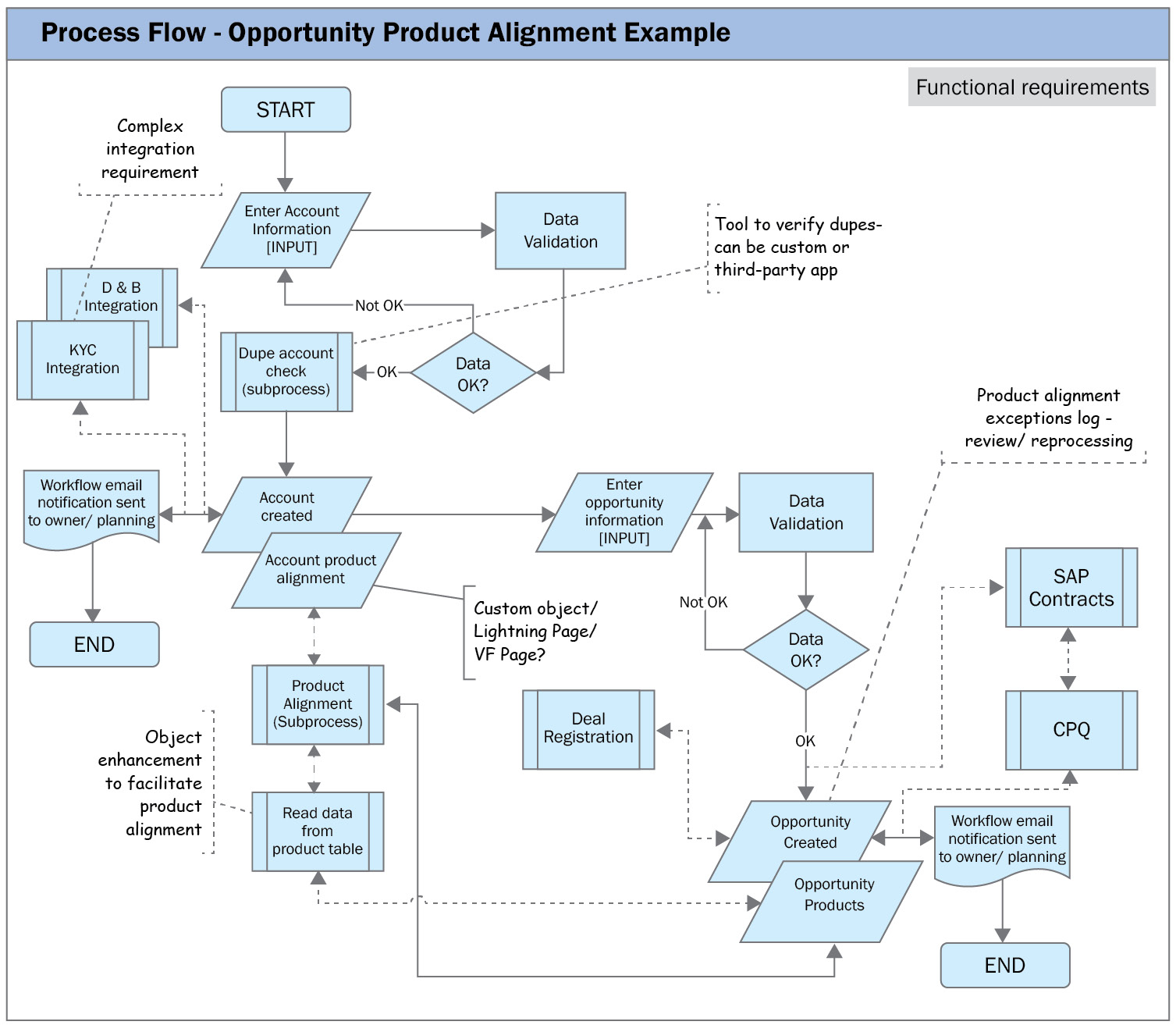
Figure 6.1 – Process flow – opportunity product alignment example (functional)
The process starts with a user (Sales Manager) creating an account record. We will try to keep the flow charts system-agnostic. Since we already know that our software system is Salesforce, I used Salesforce-specific terminology so that we can identify system-specific requirements.
Let’s walk through the process flow from start to finish:
- The user enters the necessary account information and saves the records. Then, the user inputs all the required fields and other optional fields as needed. A good practice is to input as many fields as possible since this helps other users have a complete understanding of the record.
- The system validates the data input values. Here, we verify the business rules in the form of validation rules and prompt users with appropriate user-friendly messages.
- Any validation errors that occur will prompt the user to correct the data input; for example, the KYC number should be 10 characters for US users and 12 characters for UK users.
- If the data check is good, the system triggers a dupe blocker check and flags if the record is a duplicate. For example, if the user inputs a duplicate account name, then the system lists the duplicate value so that the user can navigate to the existing record and continue with the next step – that is, opportunity creation.
- After creating the account, the product alignment sub-process kicks in and queries data from the product object. Products are added as per the business logic based on the customer attributes industry, segmentation, and route to market. The product alignment process is another complex flow on its own and in our scenario, we assume that we can align the products without any issues.
- On successful account record creation, a workflow email notification is sent to the account owner and the planning team stating that the account record has been successfully created (another business rule). Based on how you configure workflows, you will be able to generate an automated notification with a link to the account record.
- The user verifies that the products have been successfully added to the Account object. The product alignment object is a custom page/screen and lets the user manage multiple products on a single screen.
- The next step is to create an opportunity record and let the system auto-create opportunity products. In this case, the user (the Account Manager or the Deal team member) creates an opportunity record.
- The user inputs the relevant required and optional fields and saves the record. On saving, the system validates it. If no issues are found, it creates an opportunity record.
- On saving, the system reads the product alignment from the account object and creates opportunity product line items. There can be one or more opportunity product records based on product alignment on the Account record.
- Users shall be able to verify and, as needed, delete or add other products. Note that opportunity products shall be created automatically on new opportunities. Existing opportunities shall not be impacted during updates to the opportunity record.
- A formatted workflow email is sent to the opportunity owner and the planning team with opportunity details and opportunity URL links.
- The opportunity creation process ends. To simplify this process, I excluded steps such as opportunity edit, delete, and other exception steps on purpose.
- Other integrations are possible, such as D&B, KYC, CPQ, SAP, and Deal Registration. I added them as dotted boxes to give you a general idea of how complex this can get.
It takes about three iterations to create and agree on this process flow. We refine each iteration based on the feedback. The more the team collaboratively discusses the flow steps in detail, the better we will be able to identify the gaps and missed steps.
Imagine what would happen if you had just one session with a key player and you, as a Business Analyst, presented this and got an agreement without getting any feedback. What if, at each step, the flow breaks after you deploy this to production? Without accurate process flows and being able to understand every stated and unstated requirement, can this be fixed by the support team after the project team has been disbanded? I will leave this to your imagination.
Now, let’s take this through a few more iterations and collaborative workshops/CRPs with our key team members. We must question each step and see where it can go wrong and how we can make it better:
- How do we do de-dupe? Can custom code fulfill this requirement? Or can we use any available third-party tool? Who will be ultimately responsible for the data?
- Where do we capture the product alignment data? Can the user view and manage all the products on a simple screen? Do we need to account for additional development work?
- When products are added as opportunity products based on alignment, what if a record fails? How does the user fix the data? Do they add it manually or is there a way to capture the data and reprocess it automatically?
- To be able to convert account records from qualifying a lead to converting them into a customer record, customer KYC has to be completed and a KYC ID needs to be assigned to the KYC system. To enable this, do we need to build an interface or a web service call for the Salesforce system?
- Have alternative flows or options (including manual processes) been defined?
I am sure that if you review the process flow carefully, you will certainly find a few more requirements. Take a look and see if you can find two or three more. We try our best to identify all possible steps within the project’s allotted time and available resources.
Note
Our goal is to identify all technical requirements to fulfill the business needs. How and when we implement them will come during the project roadmap. They can be staggered in releases; all core functions with some level of manual workaround should start within the first release and we must keep automating as we progress through future releases. We must lay out the end-to-end workflow so that users can get from point A to point B in the best possible way.
Next, let’s review the same process flow and see if we can find any gaps concerning non-functional requirements.
Identifying non-functional requirements
Non-functional requirements specify the quality attributes of the underlying system. They are not easy to capture and not always obvious. Many of the non-functional requirements come to light only during the testing phase and especially during regression/load/stress testing. The objective of these requirements is to enable the sustained availability, reliability, and performance of the software. They help you ensure a good user experience and ease of system usage.
Take a look at the following diagram:
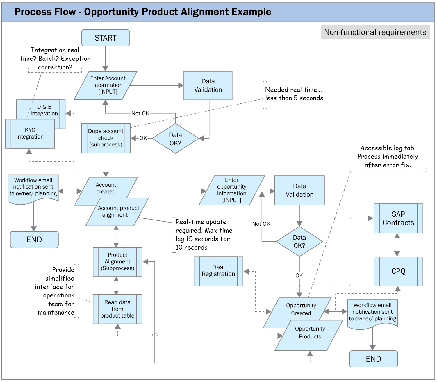
Figure 6.2 – Process flow – opportunity product alignment example (non-functional)
It gets easier to identify non-functional requirements if you draw out a flow chart and analyze it from start to end. At each step, we must analyze the non-functional aspects of every step in the flow for performance (the response time during peak usage), reliability (whether it’s reliable on mobile devices), availability (whether the system is available 99.9% of the time), and so on. Detailed collaborative sessions with multiple iterations shall yield a good set of all possible non-functional requirements. Let’s list a few here:
- What type of integration do we build with the KYC system (and integration with other systems such as CPQ and SAP)? Do we need it in real time or can it be a batch job? In this case, it may make more sense to have a batch job as the KYC process takes more time since the customer needs to be vetted and approved by multiple parties. In other instances, such as sending data to SAP contacts or the CPQ system, it makes sense to have a real-time call.
- For the Account dupe check, this should be done in real time, and it needs to happen instantly. Since every requirement needs to have quantifiable measurements, let’s say we need the check to be done in 5 seconds. How about using a vendor app? If so, can the vendor app perform the check quicker than 5 seconds?
- How many product alignment records can be associated with Account records? There will be performance issues if there are too many records and usability issues if there are too many products (the user has to scroll through multiple pages, which may be a bigger issue on mobile devices). We need to capture this requirement and quantify the measure. Let’s say that the system shall render 10 product alignment records in 15 seconds.
- We need to capture a way for the operations team to maintain the product table with product alignment attributes from the Account record.
- Upon creating the opportunity, what if the product alignment sub-process fails to create one or more product opportunities? What mechanism should we provide for users to reprocess? The same may be the case with account product alignment.
Hopefully, you can find a few more requirements if you review the flow again. Some of these non-functional requirements may vary based on what software system you implement. Also, some of them may not be obvious from a BRD or process flow perspective. For example, let’s say that we are doing a global implementation – do we need translations? This will be a significant amount of work as screen fields, reports, workflows, and so on need to be translated to user locale-specific language.
Here, you can see how easy it is for us to capture these invisible requirements by exposing them on a simple process flow chart. Also, these flows are easy to understand for the team members and help them collaborate better. Start small with a conceptual flow and keep building it iteratively. If you plan and facilitate a few sessions well with the right set of participants, I am sure your team can reflect the business process and create optimized flow charts.
We can summarize both the functional and non-functional requirements into a single flow, as shown in Figure 6.3. Some team members like them to be separate as it is easy for them to understand functional versus non-functional requirements separately. Other team members prefer to add them to a single view. Pick the one that best suits you and your team:

Figure 6.3 – Process flow – opportunity product alignment example (functional and non-functional)
With the aid of process flows, we can capture functional and non-functional process steps. Process-wise, the flow works well when the user creates new transactions (records). Does the functionality work with legacy data without any issues? This is seldom true and we need to consider migrating existing data from legacy systems. These requirements are not obvious in a process flow, so we need to make sure that we capture these requirements. Let’s review them.
Reviewing data conversion requirements
Another important set of overlooked requirements is data conversion requirements. I have seen many projects that do an excellent job of enabling new functionality with a great-looking user interface, automations, workflows, reports, and so on, but they missed one very important requirement related to legacy data. Users can only use great features and functions if they can easily access their existing legacy data in the new system in a usable format. These data requirements fall under functional and non-functional requirements.
Some key tasks that you need to think through while capturing data requirements are as follows:
- The scope of the legacy data to be converted; for example, data sources, volumes, and history data.
- Map the data from legacy values to new values.
- Scrub the legacy data so that it can be extracted before it’s converted; for example, for dedupe, completeness, and accuracy purposes.
- Dependencies between different tables/objects. Data needs to stick to the same dependencies in the target system to be usable.
- Define your Extract, Transform, and Load (ETL) processes.
Now, it’s time for us to document what have we identified so far. We will document these newly identified requirements in a functional requirement matrix.
Understanding the functional requirements matrix
The functional requirements matrix captures more granular details and elaborated functional decomposition requirements. For each BRD requirement, we will add more granularity, which may result in multiple functional requirements for each BRD requirement. We take the business requirement matrix and add additional columns to capture the checklist fields for other teams – for example, for the development team to check for requirement completeness, feasibility, and so on and for the testing team to check for requirement clarity, testability, and so on. One important column that sits next to the BRD summary is the FD summary. It spells out the description in more detail so that the development and testing teams can get more clarity and details about the requirement. Feel free to use technical jargon so that the team developing the functionality is more comfortable. You do not need to make this functional requirement matrix too complex. Reuse the BRD and add a few more fields as appropriate for your project releases. For better clarity, add functional requirements to one tab and non-functional requirements to the next tab. This will add more clarity for developers and testers. If you prefer, you can combine both into one Excel sheet.
Note
Every requirement in the functional requirement matrix should reference at least one business requirement. Also, every business requirement should map to at least one functional requirement. If not, make sure you identify the redundant (a requirement in FDM but not in BRD) or gaps/missed (a requirement in BRD but not in FDM) functional requirements.
Developing the function document
By collaboratively reviewing and developing the process flow charts, we were able to take each BRD requirement and further subdivide them into one or more functional and non-functional requirements. Each BRD item can be split into multiple functional and non-functional requirements, which the developers can use to build and unit test the sub-system or component.
Let’s take a look at the functional specification document (or functional design document):
- Introduction: Provide a brief introduction of the project:
- The purpose and core functionality that is being addressed
- What business needs and objectives are served
- Business units/countries impacted
- Other projects directly or indirectly associated
- Project stakeholders and project team members
- User roles and profiles
- Project approach: A project management approach defines your team’s mindset on how to run the projects. It depends on the project characteristics such as size, scope, and team dynamics. Based on the need of your software project, you may have to pick the right approach. It can be a traditional waterfall (plan-based), incremental (adaptive), or a mix of both:
- Methodology: Project methodologies such as waterfall, agile, hybrid, or any other methodology mandated by your PMO
- Conventions and standards: Project and Center of Excellence standards
- Assumptions: List all assumptions. For example, you can explicitly state the software system you plan to use. As an example, you can have Salesforce as the core CRM system, D&B Hoover for data enrichment, CPQ for pricing and quoting, and so on.
- Constraints: What are the constraints that may impact the project? This can include the budget, aggressive timelines, technical resource availability, conflicting projects, and integrations.
- System landscape: Briefly describe the new systems and their main features. It will be very helpful if the system’s architectural diagram is added here:
- System impacted: What systems are potentially impacted due to this release or project roadmap? Examples include SAP-OTC, CPQ, and KYC.
- System diagram: Add the system diagrams that we created earlier, including the current flow, future state flow, and process flows.
- Business workflow: List all the workflows that are exiting, as well as the new ones that have been planned as a part of this release. For example, you could add a workflow that auto-creates products on an account based on product alignment.
- Schemas/data flow diagram (DFD)/ERD: Insert the schemas/DFDs that capture how the data flows so that the developer and tester can understand them clearly and plan and execute their development work:
- Objects
- Data field attributes
- Data dictionary
- Relationships
- And more
- Functional and non-functional requirements:
- Functional requirements matrix (BRD matrix expanded)
- UI layout
- Reporting requirements: List all the reporting requirements, including the ones that need to be migrated from the legacy system (if any). This is to ensure that the specific fields that are created are accessible during reporting.
- Interface requirements: List all the interface requirements; for example, if they are real-time or batch. If a batch process is being used, then what will the frequency be, and what will the data volume be (full volume or only the delta changes)?
- Standards: Standards used during the development phase such as naming conventions, coding formats (including commenting code and code coverage), and reporting formats.
- Disaster recovery plan: List the disaster recovery plan and steps to be taken in case a system outage occurs. What will the business continuity plan be in terms of roles, responsibilities, and communication procedures? The plan should include data loss scenarios; if data loss occurs, then what is the plan to recover the data?
- Appendix: Add any relevant documents that help the technical team, such as your BRD, any conceptual flows, business presentations with key stakeholders, business plan, and so on. Add them as links or attachments.
- Acronyms and abbreviations: Company and technology-specific acronyms that are used in this document.
This is a comprehensive list of key sections in functional documents. As needed, add other relevant sections that you think add value to your implementation. Similar to BRD, you review this with technical and testing leads and SMEs, get agreement and approval from all, and lock this document. You should share this document with business SMEs and stakeholders so that they can review and provide input. However, their approval may be optional. This baseline version shall be your starting document for subsequent releases on your roadmap.
Practical tips for success
The following are a few tips that are specifically useful during solution design and functional documentation:
- The complete business process from end to end by function. For example, let’s say you have three functions – Account Management, Campaign Management, and Quote Management. Here, you should use three end-to-end process flows.
- Capture all the steps, manual or automated. Remember, process flows are system agnostic and not all steps can be automated in one release. A manual process in one release can be an automated process in a future release.
- Create process flows with input from key team members. Incorporate feedback, finalize the flow, and get agreement from this core team. All members should be on board with the overall solution design before actual development work is started.
- The functional document is the main point of reference document for the technical and testing teams. Make sure enough details are captured, if possible, in technical terms.
- The functional document should address the user interface (UI) and usability of the application for better user adoption. As needed, it will be beneficial to mock up the screen’s navigation, look, and feel.
- Address scalability requirements. If the data volumes are going to grow exponentially, the technical team needs to consider this during technical development.
- Another important aspect to consider is the performance of custom code or complex components on the page layout. For example, the product alignment page displays all the products on one page on the account record.
- How well is any system or data exception handled and logged?
- Plan the security aspects from the start. This includes a user’s access based on location, time zone, IP restrictions, MFA, encryption, and so on.
- Doing functional document peer reviews before getting it signed off helps make it a complete document. Experts with knowledge in that area can provide valuable feedback, help iron out any open issues, and provide more clarity on how to document the requirements.
Now that we’ve covered some practical tips for success, let’s summarize this chapter.
Summary
As projects grow in size and complexity, we need to make sure that we plan and allocate time and a budget for the solution architecture and solution design aspects during the design phase of the project. We can identify all the solution components and subcomponents by decomposing high-level functional requirements.
In this chapter, we learned about the solution design tasks, where we perform architectural design to identify all the steps in the process conceptually. Then, we learned about the functional and non-functional requirements with the help of process flows. Using this new knowledge of process flows, we captured the requirements in the functional requirement matrix. In the end, we reviewed a typical functional document and reviewed various important sections of the design document so that technical and testing teams can understand and use this as a baseline document for the next stage of the project.
In the next chapter, we will cover how to mock up quick semi-working solutions that we can demonstrate to stakeholders and team members and get early feedback on. We will also discuss the benefits of prototyping, conducting, and capturing the prototype by collaborating with the right stakeholders and team members.
Questions
- State a few benefits of the functional document to your technical and testing teams.
- What are the three main artifacts you may find useful during the solution design phase of your project?
- List three key participants whose input is required that you need to involve during the solution design phase.
Further reading
- Salesforce Architect’s Handbook: A Comprehensive End-to-End Solutions Guide, by Dipanker Jyoti and James A. Hutcherson
- Becoming a Salesforce Certified Technical Architect: Prepare for the review board by practicing example-led architectural strategies and best practices, by Tameem Bahri