
Chapter 11
Timecode and the AES/EBU digital audio interface
Introduction
Timecode has moved into new areas of use. It can be carried in the AES/ EBU digital interface and transmitted within the NICAM stereo sound signal. This chapter explains how it is incorporated into the digital bit stream.
AES/EBU digital interface
This interface is primarily intended to permit the sending of two channels of stereo sound in digiral form around a studio centre, existing traditional (balanced, twin-screened) audio circuits. Digital recorders have the ability to accept the digital audio data in this form. Within the code is provosion for carrying time data. This is compatible with IEC. code, though as yet there are no practical applications in wide use. One can envisage time data in the digital audio bit stream being processed by a database to aid post-production. Since audio is sent to the transmitters in AES/EBU form, it would be possible to place the time data into the 11-bit additional data word incorporated in each NICAM data block, perhaps the data could carry some form of 'advertised' programme time to automatically reporgram home videos in the vent of late changes to the transmission schedules. The data carried in the AES/EBU digital interface are organized into blocks, each block containing 192 frames. Each frame is futher divided into two subframes, with each subframe carrying alternate left and right channel audio data (though the interface does allow for data other than audio to be transmitted). Each subframe, and the start of each block, crries at its head a unique identifier, called a 'preamble'. The data, with the exception of the preambles, are coded into biphase mark form; the preambles are staright NRZ code. Figure 11.1 illustrates the process.
Each subframe consists of 32 bits. Bits 0–3 carry the preamble. This can take one of three forms:

Figure 11.1 The AES/EBU interface assembles data in blocks of 192 frames. Each frame carries two subframes. Each pair of subframes comprises 32 bits. One of these bits, STATUS, can carry timecode, referred to as ProDIO code.
- Preamble X (11100010 or 00011101) indicates the start of subframe 1 (left audio channel in stereo).
- Preamble Y (11100100 or 00011011) indicates the start of subframe 2 (right audio channel in stereo).
- Preamble Z (11101000 00010111) indicates the start of subframe 1 and the start of the block. This is necessary for synchronization, and for correct assembling of the time address bits embedded in the data stream. Figure 11.2 illustrates the three different preambles.
Bits 4–27 carry either audio data alone (in the case of 24-bit-long audio data words), or audio data preceded by 4 bits of auxiliary information (in the case of 20-bit long audio data words).
But 28 is the validity bit. If set to logical 0 it indicates that data contained in bits 4–27 are suitable for conversion into analogue form.
Bit 29 is the user bit. The bits in the 192 successive subframes within each block can be used for any purpose by the interface user. They can be formed into 24 bytes.
Bit 30 is the channel status bit. These bits within each block combine to form the channel status frame, which can carry time information.
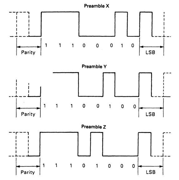
Figure 11.2 The preambles enable synchronization and identification. The preamble code is NRZ.
Bit 31 is the parity bit for 4–31 of the subframe (even parity is explicit in the preamble). Even parity is employed.
The channel status frame
This frame is formed from the individual channel status bits carried in each subframe. There are 192 of these bits within each block, assembled into a frame of 24 bytes, each byte having a specific purpose. Figure 11.3 illustrates these bytes and their functions. Since most of the bytes formed by the assembled channel status bits are unconnected with either time or synchronization they will not be described here, but a brief discussion is given in Appendix 6. Bytes 0, 4, 14–17 and 18–21 can carry time information.
Byte 0, bit 6 and bit 7 indicate the sampling frequency. This information is necessary to permit transcoding between time addresses held within the channel status frame and traditional timecode or time-of-day. The information is held in the following form:

Figure 11.3 The 24-byte sequences of the channel status data formed from the 192 status bits associated with an AES/EBU audio block.
| Bit 6 | Bit 7 | |
| 0 | 0 | Sampling frequency not indicated. Manual override permitted. |
| 0 | 1 | 48 kHz. Manual override disabled. |
| 1 | 0 | 44.1 kHz. Manual override disabled. |
| 1 | 1 | 32 kHz. Manual override disabled. |
Byte 4, bits 0-1 form the digital audio reference signal according to the following table:
| Bit 0 | Bit 1 | |
| 0 | 0 | Not a reference signal |
| 0 | 1 | Grade 1 reference signal |
| 1 | 0 | Grade 2 reference signal |
| 1 | 1 | Not defined - use is reserved |
A Grade 1 reference signal is derived from a sampling clock having an accuracy of 1 ppm (part per million) or better. A Grade 2 reference signal is derived from a clock having an accuracy of 10 ppm or better.
Bytes 14–17 (32 bits) contain the local sample address code. This is, in effect a tape timer. Bits 0–7 of each byte send the LSB first. Details of the code are given below.
Bytes 18–21 carry the time address sample. This is the time of day laid down during source encoding and will remain unchanged during subsequent processing. The time indicated is that at the start of the data block in which the address occurs. As with the tape time bytes, LSB is sent first in each byte. A value of all os indicates 'midnight', i.e. 00h 00m 00s 00f.
For both sets of time address bytes the coding is BCD. In each, the addresses is increment up each successive channel status frame (in effect, each block). With a sampling frequency of 48 kHz this represents a count incrementing up every 4 ms (192/48000). This makes conversion into IEC timecode particularly easy in its 25 fps version, as the time address needs simply to be divided by 10 for the count to increment at video frame rate.
The relationship between the time address code held in Bytes 18-21 and real time can be illustrated as follows, using 08h 05s 03f as an example:
0h 11m 05s 03f represents 736 628 frames at a 25 Hz frame rate. This is 7 366 280 X 4 ms time intervals.
Converted into binary code this becomes:
| MSB | LSB | ||
| 00000000 | 01110000 | 01100110 | 10001000 |
| (d) | (c) | (b) | (a) |
These will be embedded into bytes 18–21 as follows:
| Byte | LSB | MSB | Legend |
| 18 | 0001 | 0001 | a |
| 19 | 0110 | 0110 | b |
| 20 | 0000 | 1110 | c |
| 21 | 0000 | 0000 | d |
Bute 22, bit 6 indicates the reliability of the data held in bytes 14–17, with logical 0 indicating reliable data. Byte 22, bit 7 indicates the reliability of the data held in bytes 18–21, with logical 0 indicating reliable data.
Alternatives for timecode in AES3 channel status
Timecode is generated at one of a number of frame rates, and really needs to be independent of audio sampling rate. Equipment design would also be simpler (cheaper?) if timecode in channel status were in hours, minutes, seconds and frames rather than requiring to be transcoded into a 'number of audio samples' form, though any organization which is not totally equipped to carry audio in AES/EBU digital interface form at all stages of post-production might find that the complexities and cost of transcoding are prohibitive. At least one UK organization however, already carries time data 'in-house' as BCD hh.mm.ss.ff within the channel status, though only allowing for synchronous timecode. In 1992 a proposal (Rumsey) was submitted to the AES SC2-5-1 working party on synchronization which would free timecode in channel status for the need of synchronicity.
A data byte indicates the offset between the timecode frame start and the start of the first AES/EBU block of a new timecode frame, the first frame in a new block being flagged with a single bit. The video frame rate can be carried in 2 data bits. A 'timecode unlocked' flag could also be incorprated to indicate asynchronous operation.
Sample address code data
Either bytes 14–17 and/or bytes 18–21, which currently carry sample address codes, could carry BCD timecode data, using byte 22, bit 3 (currently reserved) as a flag.
28 of the 32 bits available can carry time data in BCD form, the remaining 4 bits indicating picture frame rate and the first block of the frame:
| Bits 0-27 | |
| Frame units | 4 bits |
| Frames tens | 2 bits |
| Seconds units | 4 bits |
| Seconds tens | 4 bits |
| Minutes units | 4 bits |
| Minutes tens | 4 bits |
| Hours units | 4 bits |
| Hours tens | 2 bits |
| Bits 28-29 | |
| 24 fps | 00 |
| 25 fps | 01 |
| 29.97 fps | 10 |
| 30 fps | 11 |
Bit 30
Set to '1' in the first block of a new timecode frame
Bit 31
Set to '1' to indicate timecode asynchronous with audio sampling rate
Indication of offset
A byte is needed to indicate the offset between the start of the timecode word and the start of the channel status block, either to accommodate asynchronous timecode, or to accommodate 625/60 and 252/60 operations, where there is not an integer number of audio samples in a video frame. There can be an offset of up to 191 samples. Byte 5 of the channel status has the only space available, currently being reserved with all bits set to zero. This byte could indicate the number of audio samples offset between the start of the timecode frame and the start of the first AES/EBU channel status block containing the new timecode frame value.
Currently work is being carried out by various working groups to define the addressing structure of AES/EBU ancillary data.