Chapter 13. Optimizing Your Network Design
Optimization is a critical design step for organizations that use high-bandwidth and delay-sensitive applications. To achieve business goals, these organizations expect their networks to use bandwidth efficiently, to control delay and jitter, and to support preferential service for essential applications. Internetworking vendors, such as Cisco, and standards bodies, such as the Institute of Electrical and Electronics Engineers (IEEE) and the Internet Engineering Task Force (IETF), offer numerous options to meet these expectations. This chapter introduces you to some of these options.
At this point in the top-down network design process, you should have a solid understanding of the logical and physical topology of your network. You should know about any links that will be shared by applications with different requirements, and you should have tested a pilot implementation of the network design to determine which links are in most need of optimization techniques.
This chapter covers optimization solutions. It assumes you have already analyzed requirements, especially application requirements for low delay or high throughput. As mentioned in Chapter 4, “Characterizing Network Traffic,” during the early phases of a design project, you should work with your customer to classify network applications into service categories so that you can determine which optimization and quality of service (QoS) options the applications will require. After you have classified an application, you should fill in the “QoS Requirements” column in Table 4-4, “Network Applications Traffic Characteristics.” As mentioned in Chapter 2, “Analyzing Technical Goals and Tradeoffs,” you should also fill in application throughput and delay goals in Table 2-2, “Network Applications Technical Requirements.”
The chapter starts with a discussion of IP multicast techniques that minimize bandwidth utilization for multimedia applications. Reducing delay is also important for multimedia applications that are sensitive to delay, such as voice and video. The “Reducing Serialization Delay” section describes some methods for ensuring that delay is minimized.
The chapter continues with a discussion of methods for optimizing network performance to meet QoS requirements. These methods allow applications to inform routers of their load and latency requirements, and let routers share QoS information among themselves and with policy servers. Later in this chapter, the section “Cisco IOS Features for Optimizing Network Performance” describes an assortment of optimization techniques offered by Cisco, including advanced switching, queuing, and traffic-shaping techniques.
Optimizing Bandwidth Usage with IP Multicast Technologies
One of the main reasons optimization techniques are required on internetworks is the increasing use of high-bandwidth, multiple-user, multimedia applications. Such applications as distance learning, videoconferencing, and collaborative computing have a need to send streams of data to multiple users, without using excessive amounts of bandwidth or causing performance problems on many systems.
The IETF has developed several IP multicast standards that optimize the transmission of multimedia and other types of traffic across an internetwork. The standards identify multicast addressing techniques that avoid the extra traffic caused by many unicast point-to-point or broadcast traffic streams. They also specify how routers learn which network segments should receive multicast streams, and how routers route multicast traffic.
Older multimedia applications that do not use multicast technologies send a data stream to every user. Such applications use a unicast point-to-point method of handling multimedia traffic that wastes bandwidth. An alternative to multiple point-to-point streams is to send a single stream and use a broadcast destination address. The obvious disadvantage with this technique is that the data stream goes to all devices, even devices for which no application is installed to handle the stream. This approach has a negative effect on performance for every device receiving the stream, including workstations, switches, and routers.
With IP multicast technologies, on the other hand, a single data stream is sent to only those stations that request the stream, thus optimizing bandwidth usage and reducing performance problems on end stations and internetworking devices.
Businesses, universities, and other organizations can use IP multicast technologies for many information-dissemination applications, including online training classes, virtual meetings, and electronic newscasts. In addition, IP multicast technologies are used in computer-simulation applications. An example is simulated military scenarios. Because it is impractical to prepare for large-scale battles with real equipment, some military institutions conduct training exercises with thousands of simulated planes, tanks, troops, weather satellites, and other devices. A plane or tank can register to receive weather and topography information for its current location by joining an IP multicast group for that location. As the plane moves, it leaves and joins new groups. This way the plane can avoid receiving information on the weather and topography for all areas (which would be overwhelming), and instead receive information relevant only to its current location. This type of application must support multicast addressing and dynamic multicast group membership, which are discussed in the next few sections.
IP Multicast Addressing
IP multicasting transmits IP data to a group of hosts that is identified by a single Class D IP address. In dotted decimal notation, host group addresses range from 224.0.0.0 to 239.255.255.255. Network stations recognize an address as being a Class D address because the first 4 bits must be 1110 in binary.
A multicast group is also identified by a MAC layer multicast address. Using a MAC layer multicast address optimizes network performance by allowing network interface cards (NIC) that are not part of a group to ignore a data stream that is not for them.
The Internet Assigned Numbers Authority (IANA) owns a block of MAC layer addresses that are used for group multicast addresses. The range of addresses for Ethernet is 01:00:5E:00:00:00 to 01:00:5E:7F:FF:FF. When a station sends a frame to an IP group that is identified by a Class D address, the station inserts the low-order 23 bits of the Class D address into the low-order 23 bits of the MAC layer destination address. The top 9 bits of the Class D address are not used. The top 25 bits of the MAC address are 01:00:5E followed by a 0, or, in binary, the following:
00000001 00000000 01011110 0
For example, when a router running the Open Shortest Path First (OSPF) routing protocol sends to the All OSPF Routers 224.0.0.5 multicast IP address, the address is converted to 01:00:5e:00:00:05 for use as the destination MAC address. Note that MAC addresses are written in hexadecimal, whereas IP addresses are written in dotted decimal notation.
As another example, when a host sends to the 233.252.16.1 multicast IP address, the address is converted to 01:00:5E:7C:10:01 for use as the destination MAC address. Follow these steps to make the conversion:
Step 1. The top 9 bits of the Class D IP address are not used, so to start, drop the first octet. In other words, drop the 233.
Step 2. Also drop the first bit of the second octet. The second octet is 252 in decimal, or 11111100 in binary. You only want the last 7 bits, however, because IEEE says the first bit must be a 0. So the number becomes 01111100 in binary, or 124 in decimal. That is 0x7C in hexadecimal.
Step 3. Use the entire third octet, which is 16 in decimal, but convert it to hexadecimal, giving you 0x10.
Step 4. Use the entire fourth octet, which is 1 in decimal, but convert it to hexadecimal, giving you 0x01.
Step 5. Prepend 01:00:5E to give you the final result of 01:00:5E:7C:10:01.
Internet Group Management Protocol
Internet Group Management Protocol (IGMP) enables a host to join a group and inform routers of the need to receive a particular data stream. IP hosts use IGMP to report their multicast group memberships to immediately neighboring multicast routers.
When a user (or system process) starts an application that requires a host to join a multicast group, the host transmits a membership-report message to inform routers on the segment that traffic for the group should be multicast to the host’s segment. Although it is possible that the router is already sending data for the group to the host’s segment, the specification states that a host should send a membership-report message in case it is the first member of the group on the network segment.
In addition to allowing hosts to join groups, IGMP specifies that a multicast router sends an IGMP query out every interface at regular intervals to see if any hosts belong to the group. A host responds by sending an IGMP membership-report message for each group in which it is still a member (based on the applications running on the host).
To lessen bandwidth utilization, hosts set a random timer before responding to queries. If the host sees another host respond for a group to which the host belongs, the host cancels its response. The router does not need to know how many or which specific hosts on a segment belong to a group. It only needs to recognize that a group has at least one member on a segment, so that it sends traffic to that segment using the IP and MAC multicast addresses for the group.
By default, a data link layer switch floods multicast frames out every port. The Cisco Group Management Protocol (CGMP) and the IETF IGMP snooping methods allow switches to participate in the process of determining which segments have hosts in a particular multicast group. CGMP is a Cisco proprietary method that lets a router send a message to switches to tell the switches about hosts joining and leaving groups. IGMP snooping is an IETF standard that causes no extra traffic but allows a switch to learn from the IGMP messages sent to routers.
Multicast Routing Protocols
In addition to determining which local network segments should receive traffic for particular multicast groups, a router must also learn how to route multicast traffic across an internetwork. Multicast routing protocols provide this function.
Whereas a standard unicast routing protocol learns paths to destination networks, a multicast routing protocol learns paths to multicast destination addresses. Multicast routing protocols help routers learn which interfaces should send each multicast stream. This section covers two multicast routing protocols: Distance Vector Multicast Routing Protocol (DVMRP) and Protocol Independent Multicast (PIM).
Distance Vector Multicast Routing Protocol
The IETF developed DVMRP to experiment with multicast routing. DVMRP is historically interesting and useful for understanding multicast routing concepts, but PIM, which is covered in the next section, is a better choice when implementing multicast routing on operational networks. DVMRP was based on the unicast Routing Information Protocol (RIP). Like RIP, DVMRP was an Interior gateway protocol (IGP), suitable for use within an autonomous system (AS) but not between different autonomous systems. DVMRP used IGMP to exchange routing updates.
The key difference between RIP and DVMRP is that RIP learns the path to a particular destination, whereas DVMRP keeps track of the return paths to the source of multicast packets. DVMRP combines many of the features of RIP with the Truncated Reverse Path Broadcasting (TRPB) algorithm.
TRPB learns how to forward multicast packets by computing the shortest (reverse) path tree between the source of a multicast packet and all possible recipients of the packet. Each multicast router determines its place in the tree, relative to the particular source, and then determines which of its interfaces are in the shortest path tree. Multicast packets are forwarded out these interfaces. A process for excluding interfaces not in the shortest path tree also exists and is called pruning.
Protocol Independent Multicast
Like DVMRP, PIM works in tandem with IGMP and with a unicast routing protocol, such as RIP, OSPF, Cisco Enhanced Interior Gateway Routing Protocol (EIGRP), and so on.
PIM has two modes: dense mode and sparse mode. The adjectives dense and sparse refer to the density of group members. Dense groups have many members. An example of a dense group is employees at a corporation who listen to the company president’s quarterly report when it is multicast on the corporate intranet. A sparse group might be a much smaller group of employees who have signed up for a particular distance-learning course.
Dense-Mode Protocol Independent Multicast
Dense-mode PIM is similar to DVMRP. Both protocols use a reverse-path forwarding (RPF) mechanism to compute the shortest (reverse) path between a source and all possible recipients of a multicast packet. Dense-mode PIM is simpler than DVMRP, however, because it does not require the computation of routing tables.
If a router running dense-mode PIM receives a multicast packet from a source to a group, it first verifies in the standard unicast routing table that the incoming interface is the one that it uses for sending unicast packets toward the source. If this is not the case, it drops the packet and sends back a prune message. If it is the case, the router forwards a copy of the packet on all interfaces for which it has not received a prune message for the source/group destination pair. If there are no such interfaces, it sends back a prune message.
The first packet for a group is flooded to all interfaces. After this has occurred, however, routers listen to prune messages to help them develop a map of the network that lets them send multicast packets only to those networks that should receive the packets. The prune messages also let routers avoid loops that would cause more than one router to send a multicast packet to a segment.
Dense-mode PIM works best in environments with large multicast groups and a high likelihood that any given LAN has a group member, which limits the router’s need to send prune messages. Because of the flooding of the first packet for a group, dense-mode PIM does not make sense in environments where a few sparsely located users want to participate in a multicast application. In this case, sparse-mode PIM, which is described in the next section, is a better solution.
Sparse-Mode Protocol Independent Multicast
Sparse-mode PIM is quite different from dense-mode PIM. Rather than allowing traffic to be sent everywhere and then pruned back where it is not needed, sparse-mode PIM defines a rendezvous point. The rendezvous point provides a registration service for a multicast group.
Sparse-mode PIM relies on IGMP, which lets a host join a group by sending a membership-report message, and detach from a group by sending a leave message. A designated router for a network segment tracks membership-report and leave messages on its segment, and periodically sends join and prune PIM messages to the rendezvous point. The join and prune messages are processed by all the routers between the designated router and the rendezvous point. The result is a distribution tree that reaches all group members and is centered at the rendezvous point.
The distribution tree for a multicast group is initially used for any source, but the sparse-mode PIM specification, RFC 4601, also provides a mechanism to let the rendezvous point develop source-specific trees to further the pruning of network traffic.
When a source initially sends data to a group, the designated router on the source’s network unicasts register messages to the rendezvous point with the source’s data packets encapsulated within. If the data rate is high, the rendezvous point can send join/prune messages back toward the source. This enables the source’s data packets to follow a source-specific shortest path tree, and eliminates the need for the packets to be encapsulated in register messages. Whether the packets arrive encapsulated or not, the rendezvous point forwards the source’s decapsulated data packets down the distribution tree toward group members.
Reducing Serialization Delay
On slow WAN links, the time to output a large packet is significant. The time to output a packet is called transmission delay or serialization delay. Serialization delay becomes an issue when a WAN link is used by applications that send large packets, such as file transfer, and applications that are delay-sensitive, such as voice, video, and interactive applications such as Telnet. Solutions to this problem include the use of link-layer fragmentation and interleaving (LFI) and the use of compression for multimedia packet headers. This section covers these solutions.
Link-Layer Fragmentation and Interleaving
LFI reduces delay on slow WAN links by breaking up large packets and interleaving the resulting small packets with packets for applications that are delay sensitive. PPP, Frame Relay, ATM, and other WAN technologies can all benefit from LFI on low-speed links, such as 56-kbps Frame Relay or 64-kbps ISDN B channels.
LFI for PPP is defined by the Multilink Point-to-Point Protocol (MPPP) standard, which is RFC 1990. LFI for PPP is relatively simple. Large packets are multilink encapsulated based on RFC 1990 and fragmented to packets of a size small enough to satisfy the delay requirements of delay-sensitive traffic. Small delay-sensitive packets are not multilink encapsulated but are interleaved between fragments of the large packets.
MPPP allows packets to be sent at the same time over multiple point-to-point links to the same remote address. The multiple links come up in response to a load threshold that you define. The load can be calculated on inbound traffic, outbound traffic, or on either, as needed for the traffic between specific sites. MPPP provides bandwidth on demand and reduces delay on WAN links.
When you configure MPPP on a Cisco router, packets arriving at an output interface are sorted into queues based on classifications that you define. After the packets are queued, large packets are fragmented into smaller packets in preparation for interleaving with time-sensitive packets. If weighted fair queuing (WFQ) is configured for an interface, packets from each queue are interleaved and scheduled (fairly and based on their weight) for transmission in the output interface queue. To ensure the correct order of transmission and reassembly, LFI adds multilink headers to the packet fragments after the packets are dequeued and ready to be sent.
In addition to supporting LFI for classic MPPP uses, such as aggregated ISDN channels, Cisco also supports LFI for Frame Relay and ATM virtual circuits. This feature implements LFI using MPPP over Frame Relay and ATM. LFI for Frame Relay and ATM supports low-speed Frame Relay and ATM virtual circuits and Frame Relay/ATM interworking (FRF.8). LFI for Frame Relay and ATM works concurrently with and on the same switching path as other QoS features, including Frame Relay traffic shaping (FRTS), low-latency queuing (LLQ), and class-based weighted fair queuing (CBWFQ).
Cisco also supports the following three methods for performing Frame Relay fragmentation:
• End-to-end Frame Relay fragmentation in accordance with the FRF.12 standard
• Trunk Frame Relay fragmentation in accordance with the FRF.11 Annex C standard
• Cisco proprietary fragmentation for voice encapsulation
Compressed Real-Time Transport Protocol
The Real-Time Transport Protocol (RTP), which is defined in RFC 3550, provides end-to-end network transport functions suitable for transmitting real-time data over multicast or unicast network services. Applications typically run RTP on top of the User Datagram Protocol (UDP) to make use of UDP’s multiplexing and checksum services. Working together with UDP, RTP implements Layer 4 (transport) functionality. Compressed RTP compresses the RTP, UDP, and IP headers to reduce serialization delay on slow links.
The RTP packet header includes several fields that specify the attributes of the data carried in the RTP packet:
• The payload type indicates the format of the payload (for example, MPEG audio or video data, JPEG video, or an H.261 video stream).
• The sequence number indicates the location of the packet in the data stream. The sequence number increments by one for each RTP data packet sent and can be used by the receiver to detect packet loss and to restore packet sequence.
• The timestamp reflects the sampling instant of the first byte in the data packet.
• The synchronization source (SSRC) field identifies the source of a stream of RTP packets (for example, a microphone or video camera). All packets from a synchronization source form part of the same timing and sequence number space, so a receiver groups packets by SSRC for playback.
• The contributing source (CSRC) list identifies sources that have contributed to the payload in the packet. An example application is audioconferencing, where the CSRC field indicates all the talkers whose speech was combined to produce the outgoing packet.
The RTP header adds important functionality that is used by multimedia applications, including video and voice over IP (VoIP). The downside of RTP is that it adds bytes to every packet, which can be an issue when a design goal is to reduce serialization delay and minimize bandwidth usage. Compressed RTP reduces delay and saves network bandwidth by compressing the RTP/UDP/IP header from 40 bytes to 2 or 4 bytes. The header can be 2 bytes when no UDP checksum is used and 4 bytes when a UDP checksum is used. The compression scheme takes advantage of the fact that, although several fields change in every packet, the difference from packet to packet is often constant. Compressing the headers is especially beneficial for slow links and small packets (such as VoIP traffic), where the compression can reduce overhead and serialization delay significantly.
Optimizing Network Performance to Meet Quality of Service Requirements
In addition to optimizing bandwidth usage by adding IP multicast, LFI, and compression features to a network design, you might determine that optimization is also needed to meet QoS requirements. The “Characterizing Quality of Service Requirements” section in Chapter 4 talked about specifying the QoS that an application requires. This section covers some techniques for meeting those requirements.
As discussed in Chapter 4, the Integrated Services working group defines two types of service that offer QoS assurances beyond best-effort service (which offers no QoS assurances):
• Controlled-load service: Provides a client data flow with a QoS closely approximating the QoS that the flow would receive on an unloaded network. The controlled-load service is intended for applications that are highly sensitive to overload conditions.
• Guaranteed service: Provides firm bounds on end-to-end packet-queuing delays. Guaranteed service is intended for applications that need a guarantee that a packet will arrive no later than a certain time after it was transmitted by its source.
Many optimization options are available to accommodate applications with controlled-load or guaranteed service requirements. The next few sections describe some of these options, starting with one that has been available for many years: the precedence and type-of-service functionality built in to the IP packet.
IP Precedence and Type of Service
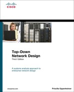
Although specialized features to support QoS have recently become a hot topic of conversation among network engineers and designers, the concept that a network must support applications with varying requirements for service is not new. The creators of IP incorporated support for different levels of precedence and types of service into the IP packet format when IP was first developed in the 1970s. Figure 13-1 shows the fields in the original IP version 4 (IPv4) header, with an emphasis on the historical Type of Service field near the beginning of the header.
Figure 13-1 Internet Protocol (IP) Header with Historical Type of Service Field
The IP Type of Service field specified both precedence and type of service. Precedence helped a router determine which packet to send when several packets were queued for transmission to the same output interface. Type of service helped a router select a routing path when multiple paths were available.
The Type of Service field was divided into two subfields (that were followed by a bit that was always set to 0):
• The 3-bit Precedence subfield supported eight levels of priority.
• The 4-bit Type of Service subfield supported four types of service.
An application used the Precedence subfield to specify the importance of a packet. The importance ranged from routine priority (the bits were set to 000) to high priority (the bits were set to 111). A value of 5 decimal was typical for VoIP and other real-time applications and is still recognized by many modern routers.
The purpose of the Type of Service subfield was to help a router select a route from a set of routes with different characteristics. The Type of Service subfield within the Type of Service field in an IP header had 4 bits (see Figure 13-1):
• Delay bit (D): Tells routers to minimize delay
• Throughput bit (T): Tells routers to maximize throughput
• Reliability bit (R): Tells routers to maximize reliability
• Cost bit (C): Tells routers to minimize monetary cost
In practice, routing protocols and routers never had good methods for addressing the needs of applications that set the type-of-service bits. Selecting a path based on the setting of the D, T, R, or C bit proved to be impractical. Although early versions of the OSPF and Border Gateway Protocol (BGP) routing protocols specified support for the bits, newer versions of OSPF and BGP specifications do not require support for routing based on the setting of the bits.
The path-selection service offered by the Type of Service subfield never materialized. The prioritization service offered by the Precedence subfield, on the other hand, is now specified by RFC 2474, “Definition of the Differentiated Services Field (DS Field) in the IPv4 and IPv6 Headers,” and RFC 2475, “An Architecture for Differentiated Services.”
IP Differentiated Services Field
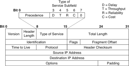
Per RFCs 2474 and 2475, the Type of Service field became the Differentiated Services (DS) field in IPv4. Bits 0 through 5 of that field are called the differentiated services codepoint (DSCP), as shown in Figure 13-2. (Per RFC 3168, bits 6 and 7 are designated as the Explicit Congestion Notification field, which is beyond the scope of this discussion.)
Figure 13-2 Differentiated Services (DS) Field
The DSCP has essentially the same goal as the Precedence subfield, which is to influence queuing and packet-dropping decisions for IP packets on an output interface of a router. RFC 2474 refers to these decisions as per-hop behaviors (PHB). The DSCP can have 1 of 64 possible values, each of which outlines a PHB. The DSCP field is backward compatible with the Precedence subfield. No attempt was made to retain compatibility with the Type of Service subfield, however.
The Assured Forwarding (AF) PHB describes a means for a provider to offer different levels of forwarding assurances for IP packets received from a customer. The AF PHB guarantees a certain amount of bandwidth to an AF class and allows access to extra bandwidth, if available. There are four AF classes, AF1 through AF4, and within each class, there are three packet-drop probabilities.
The Expedited Forwarding (EF) PHB can be used to build an assured-bandwidth, end-to-end service with low loss, latency, and jitter. Such a service appears to the endpoints like a point-to-point connection or a virtual leased line. This service has also been described as a premium service.
Note
The IPv6 header doesn’t include a DS field, but it does include an 8-bit traffic class field. This field takes on the responsibility of the IP precedence bits from the original IPv4 header and the DSCP field from the newer IPv4 header.
Resource Reservation Protocol
The Resource Reservation Protocol (RSVP) complements the IP type-of-service, precedence, DSCP, and traffic-class capabilities inherent in an IP header. RSVP supports more sophisticated mechanisms for hosts to specify QoS requirements for individual traffic flows. RSVP can be deployed on LANs and enterprise WANs to support multimedia applications or other types of applications with strict QoS requirements.
Both the IP header type-of-service capabilities and RSVP are examples of QoS signaling protocols. QoS signaling is a means of delivering QoS requirements across a network. The Type of Service field in the IP header offers in-band signaling, meaning that bits within the frame header signal to routers how the frame should be handled. RSVP offers out-of-band signaling, meaning that hosts send additional frames, beyond data frames, to indicate that a certain QoS service is desired for a particular traffic flow.
RSVP is a setup protocol used by a host to request specific qualities of service from the network for particular application data streams or flows. RSVP is also used by routers to deliver QoS requests to other routers along the path of a flow. RSVP operates on top of IP version 4 or 6, occupying the place of a transport protocol in the protocol stack (although it does not transport application data).
RSVP is not a routing protocol; it operates in tandem with unicast and multicast routing protocols. Whereas a routing protocol determines where packets get forwarded, RSVP is concerned with the QoS those packets receive. RSVP consults the local unicast or multicast routing database to obtain routes. In the multicast case, for example, a host sends IGMP messages to join a multicast group and then sends RSVP messages to reserve resources along the delivery path(s) for that group.
According to the RSVP specification, a receiver is responsible for requesting a specific QoS, not a source. Putting the onus on the receiver lets RSVP more easily accommodate large groups, dynamic group membership, and heterogeneous receiver requirements.
An application residing on a receiver host passes a QoS request to the local RSVP process. The RSVP protocol then carries the request to all the nodes (routers and hosts) along the reverse data path(s) to the data source(s) (only as far as the router located where the receiver’s data path joins the multicast distribution tree). RSVP requests should result in resources being reserved in each node along the path.
RSVP provides a general facility for creating and maintaining information on resource reservations across a mesh of unicast or multicast delivery paths. RSVP transfers QoS parameters, but does not define the parameters or the different types of services that an application can request. RSVP simply passes parameters to the appropriate traffic-control and policy-control modules for interpretation.
As part of the requirements-analysis phase of the network design process, you should have identified applications that can benefit from RSVP. You should have also selected routers to implement the design during the physical design phase. At this point in the design process, analyze your selections and take another look at the network topology to make sure routers that support RSVP are available to the applications that need it. For RSVP to be effective, each router on the path from a receiver to a source must support RSVP, including routers in redundant paths that may come into service during network outages or when the traffic load is high.
Note
Remember, network design is an iterative process that allows you to adjust your plans as you consider the details and ramifications of choices made so far.
When considering RSVP, be sure to read RFC 2208 (or any updates published after publication of this book). RFC 2208, “Resource Reservation Protocol Version 1 Applicability Statement,” points out the problems with running RSVP on a backbone router that aggregates traffic from many networks. The processing and storage requirements for running RSVP on a router increase proportionally with the number of separate sessions and RSVP reservations. Supporting RSVP on a critical backbone router that handles many data streams can overtax the router, and is inadvisable.
RSVP is more suited for private intranets than for the Internet or other public networks that cross multiple service providers’ domains. Not only are there scalability issues associated with the amount of information that routers must maintain for each RSVP session, there are also economic concerns. One service provider might be willing to provide resources (bandwidth and low delay, for example) that another service provider is not equipped to offer. A provider might not have the capacity to offer the services or the procedures to bill customers for them.
In addition, RSVP is best suited for long-duration flows, such as those present in video applications. A lot of Internet traffic consists of short-duration flows. For these reasons, RSVP is more appropriate for private networks than for the Internet. (Although this might change in the future as applications on the Internet change and more progress is made on methods for providers to cooperate.)
Common Open Policy Service Protocol
As mentioned in the previous section, RSVP simply transports QoS requests and provides techniques for routers to maintain information about the state of resource reservations. For RSVP to be effective, it needs support from additional protocols that understand actual services and policies about the services. One such protocol is Common Open Policy Service (COPS), which is specified in RFC 2748.
COPS defines a simple client/server model for supporting policy control with QoS signaling protocols such as RSVP. The COPS specification describes a basic query-and-response protocol that can be used to exchange policy information between a policy server and its clients, which will typically be RSVP routers.
The COPS specification calls a policy server a policy-decision point (PDP). It calls a client a policy-enforcement point (PEP). The protocol lets a PEP send requests, updates, and deletions to a remote PDP and lets the PDP return decisions to the PEP. In this fashion, RSVP-based routers can exchange information with centralized servers that store a network’s QoS policies, and learn how to correctly handle flows for which resources have been reserved.
Classifying LAN Traffic
The IEEE specifies a method for tagging LAN frames with a class of service (CoS) in its 802.1D document, “Standard for Local Area Network MAC (Media Access Control) Bridges.” CoS for LAN frames was originally published as a supplement to 802.1D called 802.1p. Most vendors still refer to the technology as 802.1p, and this book continues to call it 802.1p, which specifies mechanisms for switches to expedite the delivery of time-critical traffic and to limit the extent of high-bandwidth multicast traffic within a switched LAN.
IEEE 802.1p provides an in-band QoS signaling method for classifying traffic on the basis of MAC frame information. It also specifies an optional protocol mechanism in switches to support end stations dynamically registering for time-critical frame delivery or filtering services. Optional protocols between switches to convey registration information in a switched LAN are also supported.
IEEE 802.1p supports eight classes of service. A value of 0 means routine service (in other words, no priority). Different switches within a LAN, and even different ports on switches, can be configured for a different number of priority levels. A switch should have a separate queue for each priority level used by a port.
Note
It could be argued that LANs do not need QoS features. LANs that have been migrated to switched technologies and high speeds, such as 100-Mbps and Gigabit Ethernet, often have excess capacity. When backbone networks and uplink segments to upper layers of a hierarchical topology are considered, however, it becomes clear that QoS methods are necessary on LANs and enterprise networks. As new networked multimedia and voice applications become a central part of normal business practices, switched campus LANs can take advantage of 802.1p capabilities, in addition to the other capabilities already covered in this chapter.
Cisco IOS Features for Optimizing Network Performance
Cisco IOS Software provides a toolbox of optimization techniques to help you meet the challenges related to increasing traffic demands on campus and enterprise networks. The techniques include advanced switching and queuing services to improve throughput and offer QoS functionality.
Switching Techniques
In addition to running routing protocols to develop a routing topology, the major job of a router is to switch (forward) packets from incoming interfaces to outgoing interfaces. Switching involves receiving a packet, determining how to forward the packet based on the routing topology and QoS and policy requirements, and switching the packet to the right outgoing interface or interfaces. The speed at which a router can perform this task is a major factor in determining network performance in a routed network. Cisco supports many switching methods, with varying speeds and behaviors. This section describes some of these switching methods.
In general, you should use the fastest switching method available for an interface type and protocol. Using a speedy switching mode is especially important on backbone and core enterprise routers. Depending on the version of Cisco IOS Software you are running, the fastest mode might need to be configured. (It is not always the default.) You might also need to watch memory usage. The faster switching methods use more memory, so after enabling one of them, be sure to monitor free memory in the router for a brief time afterward.
This section starts by describing some older, but still used, technologies for Layer 3 switching, called the classic methods for switching, and continues with two newer technologies: NetFlow switching and Cisco Express Forwarding (CEF).
Classic Methods for Layer 3 Packet Switching
Process switching is the slowest of the switching methods. With process switching, when an interface processor receives an incoming packet, it transfers the packet to input/output memory on the router. The interface processor also generates a receive interrupt of the central processor. The central processor determines the type of packet and places it in the appropriate input queue. For example, if it is an IP packet, the central processor places the packet in the ip_input queue. The next time the Cisco IOS scheduler runs, it notes the packet in the input queue, and schedules the appropriate process to run. For example, for an IP packet, it schedules the ip_input process to run.
The input process, after the scheduler tells it to run, looks in the routing table to determine the exit interface that should be used for the Layer 3 destination address in the packet. The process rewrites the packet with the correct data link layer header for that interface and copies the packet to the interface. It also places an entry in the fast-switching cache so that subsequent packets for the destination can use fast switching.
Note that the forwarding decision is made by a process scheduled by the Cisco IOS scheduler. This process runs as a peer to other processes running on the router, such as routing protocols. Processes that normally run on the router are not interrupted to process-switch a packet. This makes process switching slow.
Fast switching allows higher throughput by switching a packet using an entry in the fast-switching cache that was created when a previous packet to the same destination was processed. With fast switching, a packet is handled immediately. The interface processor generates a receive interrupt. During this interrupt, the central processor determines the type of packet and then begins to switch the packet. The process currently running on the processor is interrupted to switch the packet. Packets are switched on demand, rather than switched only when the forwarding process can be scheduled. Based on information in the fast-switching cache, the data link layer header is rewritten and the packet is sent to the outgoing interface that services the destination.
Note
If you are using load sharing across multiple interfaces with fast switching enabled, the load might not be balanced equally if a large portion of the traffic goes to only one destination. Packets for a given destination always exit the same interface even if routing supports multiple interfaces. In other words, fast switching uses per-destination load sharing. If this is a problem, you should use CEF, which supports both per-destination and per-packet load sharing. In addition, with CEF, per-destination load sharing is based on source/destination pairs rather than simply the destination address, which may provide a better balance than fast switching does.
NetFlow Switching
NetFlow switching is optimized for environments where services must be applied to packets to implement security, QoS features, and traffic accounting. An example of such an environment is the boundary between an enterprise network and the Internet.
NetFlow switching identifies traffic flows between hosts and then quickly switches packets in these flows at the same time that it applies services. NetFlow switching also lets a network manager collect data on network usage to enable capacity planning and bill users based on network and application resource utilization. The statistics can be collected without slowing down the switching process.
To maximize network scalability, a good design practice is to use NetFlow switching on the periphery of a network to enable features such as traffic accounting, QoS functionality, and security, and to use an even faster switching mode in the core of the network. At the core of the network, the switching mode should forward packets based on easily accessible information in the packet, and generally should not spend time applying services. The next switching mode covered in this section, Cisco Express Forwarding (CEF), is optimized for the core of a network to provide high performance, predictability, scalability, and resilience.
Cisco Express Forwarding
CEF is a Cisco-patented technique for switching packets quickly across large backbone networks and the Internet. Rather than relying on the caching techniques used by classic switching methods, CEF depends on a forwarding information base (FIB). The FIB allows CEF to be much less processor-intensive than other Layer 3 switching methods because the FIB tables contain forwarding information for all routes in the routing tables (whereas a cache contains only a subset of routing information).
CEF evolved to accommodate web-based applications and other interactive applications that are characterized by sessions of short duration to multiple destination addresses. CEF became necessary when it became clear that a cache-based system is not optimized for these types of applications.
Consider a web-surfing application, for example. When a user jumps to a new website, TCP opens a session with a new destination address. It is unlikely that the new destination is in the router’s cache, unless it happens to be a destination the user, or other users, visited recently. This means that the first packet is process switched, which is slow. Also, the router’s CPU is significantly impacted if there are many first packets to new destinations. CEF improves switching speed, and avoids the overhead associated with a cache that continually changes, through the use of the FIB, which mirrors the entire contents of the IP routing table.
As mentioned in the “Classic Methods for Layer 3 Packet Switching” section, CEF supports both per-destination and per-packet load sharing. Per-destination load sharing is the default, which means that packets for a given source/destination pair are guaranteed to exit the same interface. Traffic for different pairs tend to take different paths. Unless traffic consists of flows for a small number of source/destination pairs, traffic tends to be equally distributed across multiple paths with CEF per-destination load sharing.
CEF also supports per-packet load sharing. Per-packet load sharing allows a router to send successive data packets over paths without regard to source and destination addresses. Per-packet load sharing uses a round-robin method to select the exit interface for a packet. Each packet takes the next interface that routing allows. Per-packet load sharing provides a better balance of traffic over multiple links. You can use per-packet load sharing to help ensure that a path for a single source/destination pair does not become overloaded.
Although path utilization with per-packet load sharing is optimized, packets for a given source/destination host pair might take different paths, which could cause packets to arrive out of order. For this reason, per-packet load sharing is inappropriate for certain types of data traffic, such as VoIP, that depend on packets arriving at the destination in sequence.
Queuing Services
The high-speed switching techniques discussed in the previous sections only go so far in optimizing a network that is experiencing congestion. Intelligent and fast queuing methods are also necessary. Queuing allows a network device to handle an overflow of traffic. Cisco IOS Software supports the following queuing methods:
• First-in, first-out (FIFO) queuing
• Priority queuing
• Custom queuing
• Weighted fair queuing (WFQ)
• Class-based WFQ (CBWFQ)
• Low-latency queuing (LLQ)
First-In, First-Out Queuing
FIFO queuing provides basic store-and-forward functionality. It involves storing packets when the network is congested and forwarding them in the order they arrived when the network is no longer congested. FIFO has the advantage that it is the default queuing algorithm in some instances, so requires no configuration. FIFO has the disadvantage that it makes no decision about packet priority. The order of arrival determines the order a packet is processed and output.
Note
With FIFO queuing, if there are many packets awaiting transmission, a new packet that arrives for transmission experiences delay. You may have experienced this at the grocery store. Have you ever wondered whether you should use the FIFO express checkout line even when it’s longer than the FIFO nonexpress checkout lines?
FIFO provides no QoS functionality and no protection against an application using network resources in a way that negatively affects the performance of other applications. Bursty sources can cause high delays in delivering time-sensitive application traffic, and potentially defer network control and signaling messages. Long packets can cause unfair delays for applications that use short packets. For these reasons, Cisco has developed advanced queuing algorithms that provide more features than basic FIFO queuing, including priority queuing, custom queuing, and WFQ. These algorithms are described in the next few sections.
Priority Queuing
Priority queuing ensures that important traffic is processed first. It was designed to give strict priority to a critical application and is particularly useful for time-sensitive protocols such as Systems Network Architecture (SNA). Packets can be prioritized based on many factors, including protocol, incoming interface, packet size, and source or destination address.
Priority queuing is especially appropriate in cases where WAN links are congested from time to time. If the WAN links are constantly congested, the customer should investigate protocol and application inefficiencies, consider using compression, or possibly upgrade to more bandwidth. If the WAN links are never congested, priority queuing is unnecessary. Because priority queuing requires extra processing and can cause performance problems for low-priority traffic, it should not be recommended unless necessary.
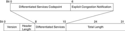
Priority queuing has four queues: high, medium, normal, and low. The high-priority queue is always emptied before the lower-priority queues are serviced, as shown in Figure 13-3. Priority queuing is analogous to a first-class line at an airport where all the clerks serve that line first until the line empties.
Custom Queuing
Custom queuing was designed to allow a network to be shared among applications with different minimum bandwidth or latency requirements. Custom queuing assigns different amounts of queue space to different protocols and handles the queues in round-robin fashion. A particular protocol can be prioritized by assigning it more queue space. Custom queuing is more “fair” than priority queuing, although priority queuing is more powerful for prioritizing a single critical application.
You can use custom queuing to provide guaranteed bandwidth at a potential congestion point. Custom queuing helps you ensure that each traffic type receives a fixed portion of available bandwidth and that, when the link is under stress, no application achieves more than a predetermined proportion of capacity. Custom queuing is analogous to a first-class line at an airport where the clerks serve that line first up to a point. After a set number of first-class passengers have been served, the clerks move on to the other people.
Figure 13-3 Behavior of Priority Queuing
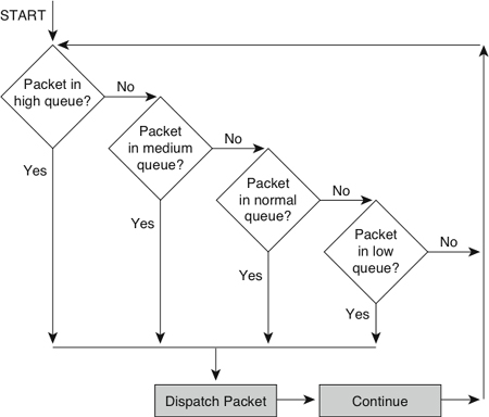
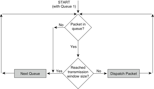
Custom queuing places a message in 1 of 17 queues. The router services queues 1 through 16 in round-robin order. (Queue 0 holds system messages, such as keepalive and signaling messages, and is emptied first.) A network administrator configures the transmission window size of each queue in bytes. After the appropriate number of packets has been transmitted from a queue such that the transmission window size has been reached, the next queue is checked, as shown in Figure 13-4.
Weighted Fair Queuing
WFQ is a sophisticated set of algorithms designed to reduce delay variability and provide predictable throughput and response time for traffic flows. A goal of WFQ is to offer uniform service to light and heavy network users alike. WFQ ensures that the response time for low-volume applications is consistent with the response time for high-volume applications. Applications that send small packets are not unfairly starved of bandwidth by applications that send large packets. Bandwidth is divided up equitably in an automated way.
WFQ is a flow-based queuing algorithm that recognizes a flow for an interactive application and schedules that application’s traffic to the front of the queue to reduce response time. Low-volume traffic streams for interactive applications, which includes a large percentage of the applications on most networks, are allowed to transmit their entire offered loads in a timely fashion. High-volume traffic streams share the remaining capacity.
Figure 13-4 Behavior of Custom Queuing
Unlike custom and priority queuing, WFQ adapts automatically to changing network traffic conditions and requires little to no configuration. It is the default queuing mode on most serial interfaces configured to run at or below E1 speeds (2.048 Mbps).
For applications that use the IP Precedence subfield in the IP header, WFQ can allot bandwidth based on precedence. The algorithm allocates more bandwidth to conversations with higher precedence, and makes sure those conversations get served more quickly when congestion occurs. WFQ assigns a weight to each flow, which determines the transmit order for queued packets. IP precedence helps determine the weighting factor.
WFQ also works with RSVP, which uses WFQ to allocate buffer space, schedule packets, and guarantee bandwidth based on resource reservations. Additionally, WFQ understands the discard eligibility (DE) bit and the forward explicit congestion notification (FECN) and backward explicit congestion notification (BECN) mechanisms in a Frame Relay network. After congestion has been identified, the weights used by WFQ are altered so that a conversation encountering congestion transmits less frequently.
Class-Based Weighted Fair Queuing
CBWFQ combines the best elements of priority, custom, and weighted-fair queuing. CBWFQ results in a more complex configuration than the other queuing methods, but the complexity adds flexibility not found in the other methods. CBWFQ lets you define traffic classes based on match criteria such as protocols, access control lists, and input interfaces. Packets satisfying the criteria for a class constitute the traffic for that class. A FIFO queue is reserved for each class, and traffic belonging to a class is directed to the queue for that class.
After a class has been defined, you can assign characteristics to it such as bandwidth and the maximum number of packets that can be queued for the class, called the queue limit. The bandwidth assigned to a class is the guaranteed bandwidth delivered to the class during congestion. The queue limit for the class is the maximum number of packets allowed to accumulate in the queue for the class. To optimize how packets are dropped if they exceed the queue limit, you can enable weighted random early detection (WRED), which is covered later in this chapter.
Flow classification for CBWFQ is based on WFQ. That is, packets with the same source IP address, destination IP address, source TCP or UDP port, and destination TCP or UDP port are classified as belonging to the same flow. WFQ allocates an equal share of bandwidth to each flow. Flow-based WFQ is also called fair queuing because all flows are equally weighted.
When CBWFQ is enabled, packets that arrive at an output interface are classified according to the match criteria you defined. The weight for a packet belonging to a specific class is derived from the bandwidth you assigned to the class when you configured it. In this sense, the weight for a class is user configurable. After the weight for a packet is assigned, the packet is placed in the appropriate queue. CBWFQ uses the weights assigned to the queued packets to ensure that the class queue is serviced fairly.
Low-Latency Queuing
LLQ combines priority queuing with CBWFQ and was originally called PQ-CBWFQ, but even Cisco recognized that acronyms can only be so long before they lose their mnemonic value. LLQ brings strict priority queuing to CBWFQ. Strict priority queuing allows delay-sensitive data such as voice to be sent before packets in other queues are sent.
Without LLQ, CBWFQ provides WFQ based on defined classes with no strict priority queue available for real-time traffic. As mentioned in the preceding section, CBWFQ allows you to define traffic classes and then assign characteristics to each class. For example, you can specify the minimum bandwidth delivered to a class during congestion. When you are using CBWFQ, the weight for a packet belonging to a specific class is derived from the bandwidth you assigned to the class when you configured it. Therefore, the bandwidth assigned to the packets of a class determines the order in which packets are sent. All packets are serviced fairly based on weight, and no class of packets is granted strict priority. This scheme poses problems for voice traffic that is intolerant of delay and variation in delay (jitter).
LLQ enables use of a single, strict-priority queue within CBWFQ at the class level, allowing you to direct traffic belonging to a class to the CBWFQ strict-priority queue. Although it is possible to place various types of real-time traffic in the strict-priority queue, Cisco strongly recommends that you direct only voice traffic to the queue. Voice traffic requires that delay be nonvariable. Real-time traffic such as video could introduce variation in delay, thereby thwarting the steadiness of delay required for successful voice transmission. LLQ is an essential tool for network designers who plan to transmit voice traffic on low-bandwidth links that also carry other types of traffic.
Random Early Detection
The queuing mechanisms discussed in the previous sections are essentially congestion-management techniques. Although such techniques are necessary for controlling congestion, they fall short of avoiding congestion before it occurs. A new class of congestion-avoidance algorithms is gaining popularity.
One such algorithm is random early detection (RED), which works by monitoring traffic loads at points in a network and randomly discarding packets if congestion begins to increase. The result is that source nodes detect the dropped traffic and slow their transmission rate. RED is primarily designed to work with applications based on the Transmission Control Protocol (TCP).
Upon packet loss, a TCP session decreases its transmit window size, effectively slowing its transmission rate. It then gradually increases the window size until congestion occurs again. The term porpoising is sometimes used to refer to the closing and reopening of windows. (Picture a porpoise jumping in and out of water.)
Experience shows that if routers do not apply some sort of randomization to the dropping of packets, multiple TCP sessions tend to slow their transmission rate simultaneously. (The sessions take a synchronized porpoise dive, which in more technical terms is often called global synchronization.) Multiple applications lower and increase their transmission rate simultaneously, which means that bandwidth is not used effectively. When multiple applications slow down, bandwidth is wasted. When they increase their rate, they tend to increase bandwidth utilization to the point where congestion occurs again.
The advantage of RED is that it randomizes the dropping of packets, thus reducing the potential for multiple sessions synchronizing their behavior. RED is a good solution for a central-site router in a hub-and-spoke topology. RED distributes the dropping of packets across many of the spoke networks and avoids causing congestion problems for multiple application sessions from one site.
Weighted Random Early Detection
Weighted Random Early Detection (WRED) is the Cisco implementation of RED. WRED combines the capabilities of the standard RED algorithm with IP precedence. This combination provides for preferential traffic handling for higher-priority packets. It selectively discards lower-priority traffic when an interface starts to get congested, rather than using simply a random method. WRED can also adjust its behavior based on RSVP reservations. If an application registers for the Integrated Services working group controlled-load QoS service, WRED is made aware of this and adjusts its packet discarding accordingly.
Flow-based WRED classifies incoming traffic into flows based on parameters such as destination and source addresses and ports. Flow-based WRED uses this classification and state information to ensure that each flow does not consume more than its permitted share of the output buffer resources. Flow-based WRED determines which flows monopolize resources and more heavily penalizes these flows.
Traffic Shaping
Another tool that is available to network designers using Cisco equipment is traffic shaping, which enables you to manage and control network traffic to avoid bottlenecks and meet QoS requirements. It avoids congestion by reducing outbound traffic for a flow to a configured bit rate, while queuing bursts of traffic for that flow. In topologies with routers and links of varying capabilities, traffic can be shaped to avoid overwhelming a downstream router or link.
Traffic shaping is configured on a per-interface basis. The router administrator uses access control lists to select the traffic to shape. Traffic shaping works with a variety of Layer 2 technologies, including Frame Relay, ATM, Switched Multimegabit Data Service (SMDS), and Ethernet.
On a Frame Relay interface, you can configure traffic shaping to adapt dynamically to available bandwidth using the BECN mechanism. In addition, Cisco has a specific feature for Frame Relay networks called Frame Relay traffic shaping that supports optimization techniques specific to Frame Relay.
Committed Access Rate
Cisco also supports a feature called committed access rate (CAR) that enables you to classify and police traffic on an incoming interface. CAR supports specifying policies regarding how traffic that exceeds a certain bandwidth allocation should be handled. CAR looks at traffic received on an interface (or a subset of that traffic selected by an access control list), compares its rate to a configured maximum, and then takes action based on the result. For example, it can drop a packet or change the IP precedence bits in the packet to indicate that the packet should be handled with lower priority.
Summary
To meet a customer’s goals for network performance, scalability, availability, and manageability, you can recommend a variety of optimization techniques. Optimization provides the high bandwidth, low delay, and controlled jitter required by many critical business applications.
To minimize bandwidth utilization for multimedia applications that send large streams of data to many users, you can recommend IP multicast technologies. These technologies include multicast addressing, Internet Group Management Protocol (IGMP) for allowing clients to join multicast groups, and multicast routing protocols such as DVMRP and PIM.
Multimedia and other applications that are sensitive to network congestion and delay can inform routers in the network of their QoS requirements using both in-band and out-of-band methods. An in-band method involves setting bits within packets to specify how the packet should be handled. For example, IPv4 includes the Differentiated Services field, and IPv6 includes the traffic class field. IEEE 802.1p also has a way of specifying priority within data link layer frames.
Resource Reservation Protocol (RSVP) is an out-of-band method for specifying QoS. It can be used with the Common Open Policy Service (COPS) protocol, which standardizes the client/server communication between policy-enforcement points (PEP), such as routers, and policy servers, also known as policy-decision points (PDP).
After a network has been upgraded to include QoS features, applications that use RTP can be deployed. Real-Time Transport Protocol (RTP) provides a transport layer service suitable for transmitting real-time audio and video data over multicast or unicast network services. To avoid extra serialization delay caused by the addition of an RTP header to multimedia packets, compressed RTP should be used, especially with voice packets.
Cisco supplies a number of features for optimizing a network, including NetFlow switching, Cisco Express Forwarding (CEF), advanced queuing services, random early detection (RED), and traffic shaping.
Review Questions
- How does multicast routing differ from unicast routing?
- This chapter mentions serialization delay (also sometimes called transmission delay). What other types of delay are there? List and describe three other types of delay.
- What are some techniques for reducing serialization delay?
- As mentioned in the “Link-Layer Fragmentation and Interleaving” section, PPP, Frame Relay, ATM, and other WAN technologies support fragmenting packets (frames) at Layer 2. As you may have learned in basic networking classes, IP can also fragment packets at Layer 3. What are some advantages and disadvantages of fragmenting at Layer 3 versus fragmenting at Layer 2?
- Research the problem known as “TCP global synchronization.” How can RED reduce the likelihood of TCP global synchronization?
Design Scenario
In Chapter 11, “Selecting Technologies and Devices for Enterprise Networks,” you learned about the network design project for Klamath Paper Products. Klamath plans to roll out an ongoing distance-learning program that will train employees and other companies on ways to conserve raw materials, use recycled materials, and work more efficiently. Executive management considers the new training program vital to the continued success of Klamath and approved funding to equip the training rooms at most sites with digital videoconferencing systems.
- Based on Klamath’s requirements, select some network optimization technologies that will help maintain video quality for the distance-learning program. Based on Figure 11-6, “New Core WAN at Klamath,” draw a network topology map for Klamath and indicate where your optimization techniques will be deployed. Include with the network drawing a written explanation of the optimization techniques.
- As discussed in Chapter 11, in the future, Klamath plans to dismantle its legacy voice network. The legacy voice traffic that is currently carried on dedicated 64-kbps circuits will be updated to use VoIP technology. All voice, video, and data traffic will traverse Klamath’s new Metro Ethernet network. What additional optimization techniques will you add to your network design to support the VoIP traffic? Update your network topology drawing and written explanation to indicate optimization techniques for the VoIP traffic.