2
Evolution of Mobile Communication Networks
Christian Mannweiler1, Cinzia Sartori1, Bernhard Wegmann1, Hannu Flinck2, Andreas Maeder1, Jürgen Goerge1, and Rudolf Winkelmann1
1Nokia Bell Labs, Munich, Germany
2Nokia Bell Labs, Espoo, Finland
3Nokia, Mobile Networks, Munich, Germany
In 2019, the Third Generation Partnership Project (3GPP) officially completed the specification of Release 15, also referred to as the Phase 1 of the fifth generation (5G) of 3GPP mobile networks. This release has defined a completely new radio system complemented by a next‐generation core network and includes the specifications for both standalone (SA) and non‐standalone (NSA) operation of 5G New Radio (NR).
This chapter presents the evolution of mobile communication networks from GSM to the 5G System (5GS). The ever more demanding performance requirements are motivated by describing the evolution of communication services to be supported by mobile networks. Important technical milestones of each system generation are described, focusing on fundamental system design choices, overall system architecture, individual network features in different domains including radio, core, and transport networks, as well as selected technological and protocol enhancements. The chapter also describes the supported communications services and the mobile network architectures and technologies that have been developed from 2G to 5G in order to address the requirements of the listed services. The evolution of important network technologies, concepts, and functional architectures in the domains of radio access network (RAN), CN, and transport networks across network generations are analysed with respect to their relevance for network management.
The chapter then presents 5G system design as well as individual capabilities. 5G mobile networks are introduced by highlighting the key technological enablers. Starting from an overall system perspective, the chapter also presents the most important novelties in the 5G RAN and features of NR. The discussion is then extended to evaluate the impact on transport networks.
The chapter concludes with an evaluation of the network management approaches for pre‐5G networks, detailing the management system architecture, interactions between managing functions and managed objects, and the approach for modelling network elements and network data. The shortcomings of traditional network management approaches are described: while specific components, such as, Self‐Organizing Network (SON) functions, will remain a crucial part of 5G management systems, novel capabilities are required to address the need for automation and cognitive behaviour of the network management procedures.
2.1 Voice and Low‐Volume Data Communications
Mobile communication systems are typically classified into network generations. The first generation of mobile communication networks was based on circuit switched analogue technologies. It became available in the 1980s with the aim of providing ubiquitous voice services. This was not widely adopted owing to low inter‐operability amongst the technologies, an issue which was addressed starting from the second generation. Table 2.1 gives an overview of the sequence of generations over the last decades, starting with the second generation, the first standard of the series to be developed by the 3GPP, which today is the leading organization in the specification of mobile communication systems. The Global System for Mobile Communications (GSMs) is the most prominent representative of 2G mobile communication networks. In Europe, GSM networks have been deployed starting from the early 1990s, offering voice and low‐volume data service to the subscribers. The design of the third generation (3G) mobile communications system, Universal Mobile Communications System (UMTS) started in the late 1990s and 2000s to enhance the data services provided by mobile networks.
Table 2.1 Overview of 3GPP releases and mobile network generations.
| Network generation | Year | First 3GPP release |
| 2G GSM | 1992 | GSM Phase 1 |
| ‘2.5G’ GPRS | 1997 | GSM Phase 2+/Rel. 97 |
| 3G UMTS | 2000 | Rel. 99 |
| ‘3.5G’ HSDPA | 2002 | Rel. 5 |
| LTE | 2008 | Rel. 8 |
| 4G LTE‐A | 2011 | Rel. 10 |
| ‘4.5G’ LTE‐A Pro | 2016 | Rel. 13 |
| 5G new radio | 2018 | Rel. 15 |
2.1.1 Service Evolution – From Voice to Mobile Internet
Pre‐5G mobile network generations already had to serve a continuously increasing variety of applications characterized by different traffic profiles and the associated Quality of Service (QoS) requirements. While second‐generation networks were mainly designed to carry voice traffic and low‐volume data service, the major novelty in 3G networks constituted mobile Internet access, particularly web browsing, access to mail service and streaming services with medium data rates.
In the 1990s, the second generation (2G) GSM [1] replaced the first generation. GSM is based on Time‐Division Multiple Access (TDMA) and were the first digital wireless technologies which extended voice services to a vast population. In addition to voice, GSM introduced services such as text messages Short Message Service (SMS), fax services, voice mail, and High‐Speed Circuit‐Switched Data (HSCSD), with data rates of up to 57.6 kbps by aggregating four radio channels of 14.4 kbps. SMS has always been very popular, reaching its peak volume in 2011 and only slowly decreasing thereafter. SMS was the first coexisting data service in a circuit‐switched system and used a control channel of GSM. A single text message comprises a maximum of 160 characters with best effort QoS profile. Multimedia Messaging Service (MMS), allowing the transmission of multimedia content up to 300 kB, was introduced in 2002, but never reached a comparable level of popularity. In contrast, SMS still plays a role today, e.g. IoT services with low data rates and relaxed latency constraints or for online payment systems (short message service‐transaction authentication number (SMS‐TAN)) or in developing countries for interaction with authorities.
As a circuit‐switched system, GSM is particularly tailored for voice communication. Initially, the utilized voice codecs (full rate, FR and half rate, HR) required a transmission data rate of up to 13 kbps and allowed a trade‐off capacity (HR) for quality (FR). FR is very robust even in the case of fluctuating radio channel quality since it allows for the identification of the more important parts within the encoded audio signal, so that those parts can be prioritized accordingly for radio transmission, e.g. using stronger channel coding. In 1997, the enhanced full rate (EFR) codec was introduced, which required a marginally lower data rate of 12.2 kbps while providing improved speech quality. EFR uses the same algorithm as the 12.2 kbps mode of the Adaptive Multi‐Rate Narrowband (AMR‐NB) speech codec. AMR‐NB, with a total of eight‐bit rate modes, was adopted as the standard codec by 3GPP in 1999.
GSM only provides very limited capacity for data transmission. UEs can only be allocated a single channel and the effective data rate is limited to 9.6 kbps. To cope with the growth of the Internet market, GPRS (General Packet Radio Service) was specified in the late 1990s, which achieved data rates of up to 172 kbps by allocating multiple time slots of a GSM frame to a single UE. Later, Enhanced Data Rates for GSM Evolution (EDGE) increased the data rate to around 230 kbps by introducing a more efficient modulation scheme, which allows for a maximum data rate of 59.2 kbps per time slot, and by bundling of four time slots per UE. In 2016, 3GPP standardized ‘Extended Coverage GSM (EC‐GSM)’, a low‐power Internet of Things (IoTs) protocol based on EDGE/GPRS for support of cellular IoT.
In the late 1990s, 3GPP developed the UMTS, the third generation (3G) global standards [2]. The radio technology changed to Wideband Code Division Multiple Access (WCDMA) to fulfil the performance requirements of International Mobile Telecommunication‐2000 (IMT‐2000). IMT‐2000 was required to support multi‐media (voice, data, video) traffic with data rates of up to 2 Mbps in stationary conditions and 384 kbps while moving at moderate speeds. The main goal of 3G was to increase of user bit rates on the radio interface to satisfy the expected demand for more data‐intensive services, such as mobile video telephony or faster downloads. To support different services, four traffic classes with different latency sensitivity and throughput were identified: (i) conversational, (ii) streaming, (iii) interactive, and (iv) background class. The distinguishing characteristics of the classes are data rate and delay sensitivity. Table 2.2 depicts the UMTS QoS classes, their fundamental characteristics, and example applications.
| Traffic class | Fundamental characteristics | Example application |
| Conversational class |
|
Voice, video telephony, video games |
| Streaming class |
|
Streaming multimedia |
| Interactive class |
|
Web browsing, network games |
| Background class |
|
Background download of emails |
In the conversational QoS class, the AMR‐Wideband (AMR‐WB) speech codec offers nine source data rates between 6.6 and 19.85 kbps. The bit rate is controlled by the RAN depending on load conditions and channel quality. In terms of end‐to‐end delay, a maximum value of 400 ms shall not be exceeded.
The maximum (downlink) data rate increased from 384 kbps in the original release (Release 99) to typically 7.2 Mbps (for the most common terminals of category 8) and 42.2 Mbps for MIMO‐capable terminals, respectively. In uplink direction, maximum data rates increased from 384 kbps to 11.5 Mbps. To cope with the continuous surge in data traffic volume, 3GPP standardized High‐Speed Downlink Packet Access (HSDPA) in Rel. 5 and later enhanced this to Evolved High‐Speed Packet Access (HSPA+) in Rel. 7 [4]. Multi‐carrier HSPA+ specified in further 3GPP releases, allows a theoretical data throughput of 337 Mbps in the downlink and 34 Mbps in the uplink.
2.1.2 2G and 3G System Architecture
The gradual transition from 2G to 3G networks also marked the shift from predominant voice services to increasingly important data services. Therefore, support for packet‐based data transfer in the core network has already been introduced in GPRS and EDGE. Since the air interface still behaved like a circuit‐switched call, part of the efficiency associated with a packet‐based connectivity was lost. The main network elements (NEs) of the 2.5G GSM/(E)GPRS system are the Base Station Subsystem (BSS), which form the GSM EDGE Radio Access Network (GERAN), and the Core Network (CN). The Packet Control Unit (PCU) introduced for GPRS‐EDGE is normally placed in the BSS, although the standard also foresees the possibility of having it in the Serving GPRS Support Node (SGSN) of the CN.
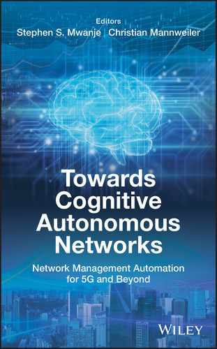
While the 3G/3.5G RAN is very different from the 2G/2.5G RAN and required operators to deploy new radio networks, the CN architecture substantially remained unchanged. The CN of the 2.5G and 3G/3.5G systems is composed of two domains: the circuit‐switched (CS) domain providing services like voice or SMS, and the packet‐switched (PS) domain providing IP‐based services, cf. Figure 2.1. The 3G CN is an evolution of the 2G CN architecture, complemented with elements for new functionalities. The main NEs of the system architecture comprise:
- The Mobile Station (MS) is a combination of a terminal equipment (also referred to as Mobile Equipment, ME) and a separated module, the 2G Subscriber Identity Module (SIM)/3G Universal Subscriber Module Identity (USIM) where the subscriber data are stored.
- The RAN comprises of the 2G GSM EDGE Radio Access Network (GERAN) and the 3G UMTS Terrestrial Radio Access Network (UTRAN), which are described in Sections 2.1.3 and 2.1.4, respectively.
- The Home Location Register (HLR) contains all subscriber data and their last known location and the Visitor Location Register (VLR) contains temporary subscriber information. The Authentication Centre (AuC) is a protected database holding the same secret keys as in the user's (U)SIM card.
- Circuit‐switched core: the Mobile Switching Centre Server (MSS) carries circuit‐switched data while the Gateway MSC (GMSC) terminates call control interfaces to external networks. From Rel. 4, the MSS was split into control and user plane functions, the MSS and Media Gateway (MGW) respectively.
- Packet‐switched core: the Serving GPRS Support Node (SGSN) provides, amongst others, user authentication, mobility management, and session management by setting up PDP connections through which data are sent to external Packet Data Networks (PDNs). Since the SGSN performs the same functions as the MSS for voice traffic, they are typically collocated. The Gateway GPRS Support Node (GGSN) serves as the gateway towards an operator's IMS or to external PDNs.
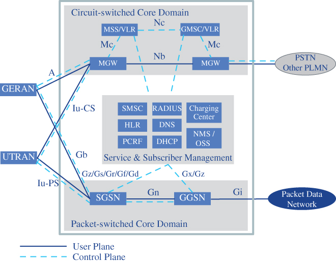
Figure 2.1 Architecture of 2G and 3G mobile networks.
While Rel. 4 still supports both the circuit‐switched and packet‐switched domains in the CN, the CN of Rel. 5 is fully IP‐based, including voice services. Both SGSN and GGSN are upgraded to support circuit‐switched services like voice. The Call State Control Function (CSCF) provides call control functionality for multimedia sessions and the Media Gateway Control Function (MGCF) controls media gateways. The Media Resource Function (MRF) supports features such as multi‐party conferencing.
2.1.3 GERAN – 2G RAN
The second generation (2G) of mobile communication was almost completely voice‐dominated, the architecture and system design followed the circuit switched approach with setting up and release of dedicated channels for voice calls [5]. Robustness against call drops was the main driver for an interference avoiding cellular network deployment. Cell and frequency planning were the most important operations before the installation of the system, i.e. substantial offline optimization effort took place during the planning phase. Frequency reuse is the core concept of cellular GSM network, where the same frequency is simultaneously used in geographical areas with sufficient distance to eliminate co‐channel interference between adjacent cells.
The GERAN architecture consists of a base transceiver station (BTS) and base station controller (BSC). As depicted in Figure 2.2, several BTSs and one BSC build the so‐called base station subsystem (BSS) using the Abis interface between BTS and BSC. The BSC manages the radio resources for one or more BTSs, it handles radio channel setup, frequency hopping, and handovers. The BSS also includes a transmission and rate adaptation unit (TRAU) which transforms GSM speech coded signals into Integrated Services Digital Network (ISDN) format used in network and switching subsystem (NSS). A high‐speed line (T1 or E1) is used to connect the BSS with the Mobile Switching Centre (MSC) linked via the A interface, while mobile devices are linked via the so‐called Um interface. The MSC belongs to the NSS which includes other core network elements like HLR, VLR, and AuC. To connect to another network, a GMSC is required.
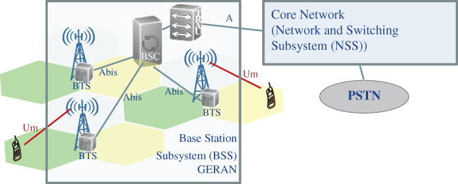
Figure 2.2 GERAN architecture.
2.1.4 UTRAN – 3G RAN
The UTRAN resembles the GERAN architecture consisting of multiple radio network subsystems (RNSs), where an RNS consists of one radio network controller (RNC) which controls and serves, depending on the manufacturer, up to several thousands of base stations called Node B (NB). Each Node B can provide service to multiple cells. A cell is defined as a certain sector with a specific carrier frequency.
As depicted in Figure 2.3, the newly standardized interfaces of the UTRAN architecture are the Iub interface between Node B and the RNC and the Iur between two RNCs. In the first UTRAN Release (Rel. 99), these logical interface connections are established by means of Asynchronous Transfer Mode (ATM)‐transport links. The Iu interface connects the UTRAN with the Core Network (CN) which can be instantiated as Iu‐CS for circuit‐switched connection with MSC (like the A interface in GSM) and as Iu‐PS to connect with the packet‐switched part of the CN. From 3GPP Rel. 4, ATM transport links were replaced by Internet Protocol (IP) connectivity with mechanisms like Multi‐Protocol Label Switching (MPLS) as a suitable alternative to manage different traffic classes with guaranteed QoS (cf. Section 2.5).
Figure 2.3 UTRAN architecture with interfaces to the core network.
The UMTS air interface connecting the UTRAN with the user equipment (UE) is called Uu interface and is the most considerable technology change between GSM/GPRS networks and UMTS networks. While GSM/GPRS used TDMA technology with multiple narrow‐band 200 kHz carriers as multi‐user access technology, for UMTS networks WCDMA was chosen with 5 MHz carrier bandwidth. Furthermore, from spectrum usage perspective, UMTS is offering both duplex modes, namely frequency division duplex (FDD) and time division duplex (TDD), while GSM was only operating in FDD mode combined with a quasi TDD component to support the duplex separation by means of a fixed time shift of the uplink and downlink slots.
Another remarkable difference is the frequency reuse factor of 1 in UTRAN. This is a result of the soft capacity philosophy of CDMA. However, it also requires new RRM methods like soft handover (SHO) or sometimes also called macro diversity, where the UE is simultaneously connected to two or more different cells. This guarantees smooth and failure‐free cell changes on the expense of cell capacity, since resources in several cells are assigned to transmit the same information. The UE stays in the same carrier, while in GSM, the terminal must re‐tune the frequency along with the cell change resulting in a hard handover with short disconnection. UMTS no longer needs the labour‐intensive frequency reuse planning on expense of the (less crucial) scrambling code planning. Staying with mobility robustness example, the 3G approach with soft and softer (intra‐frequency) handover is rather robust per se. However, the cell breathing effect is increasing the network planning complexity to balance between too many SHO links and failures due to intercell interference.
Introducing high‐speed packet access (HSPA) to UMTS supported improvement in end‐user experience with cost‐efficient mobile broadband (e.g. mobile Internet), seen as an interim generation step called 3.5G [6]. It started with HSDPA (high speed downlink packet access) in 3GPP Rel. 5 and Rel. 6 introduced a new transport channel in the uplink, known as high speed uplink packet access (HSUPA) which allows for sending of large e‐mail attachments, pictures, video clips, etc.
There has only been a limited number of evolutionary architectural changes for 3G, mainly related to radio resource management (RRM) and scheduling. While in Rel. 99, scheduling and retransmissions were handled by the RNC, this functionality was moved to the Node B in HSPA in Rel. 5. This placement closer to the air interface ensured faster reaction with Hybrid Automatic Repeat reQuest (HARQ) and lower latency. Another remarkable function of HSPA is the fast channel‐dependent scheduling in a TDM manner providing a gain referred to as multi‐user diversity.
2.2 Mobile Broadband Communications
Similar to 3G, the development of the fourth generation (4G) of mobile networks was driven by the subscribers' and the industry's demand for increased throughput due to new services requiring even higher data rates. Accordingly, the requirements of the International Mobile Telecommunications‐Advanced (IMT‐Advanced) report, issued by ITU‐R in 2008, mandate, among others, a nominal downlink throughput of 100 Mbps for mobile users, increased spectral efficiency, and a scalable channel bandwidth. In general, 4G systems shall provide an adequate QoS for the most important services, amongst them mobile broadband access, video chat, mobile TV, and (at that time new) services like high‐definition television (HDTV).
2.2.1 Mobile Broadband Services and System Requirements
To cover these QoS requirements, the most widely used system for 4G mobile networks, Evolved Packet System (EPS) of the 3GPP implements several mechanisms to provide the appropriate QoS in both the radio access (E‐UTRA, Evolved Universal Terrestrial Radio Access) and the core network (EPC, Evolved Packet Core). Most importantly, for 4G, 3GPP has introduced the notion of an EPS bearer that is associated with a set of QoS parameters, namely QoS Class Identifier (QCI), Allocation and Retention Priority (ARP) as well as Maximum Bit Rate (MBR) and Guaranteed Bit Rate (GBR) values for uplink and downlink. The EPS bearer defines the end‐to‐end QoS granularity of the system, allowing for a fine‐grained definition of QoS parameters for the service to be delivered by the bearer. The QCI, in an integer from 1 to 9, indicates nine different QoS performance characteristics, such as resource type (GBR or Non‐GBR), priority (1–9), packet delay budget (50–300 ms), and packet error loss rate (10−2 down to 10−6). ARP defines a bearer's priority level (1–15) and its pre‐emption capability and vulnerability. For example, for conversational voice service, the following standardized QCI characteristics are defined: QCI = 1, priority level = 2, packet delay budget = 100 ms, and allowed packet error/loss rate = 10−2. For buffered streaming and TCP‐based services, two QCI values with different priority levels are defined [7]. The lowest standardized packet delay budget for the EPS, defined for, e.g. V2X, augmented reality, or discrete automation traffic, is 10 ms.
Regarding maximum data rates, the level of spatial multiplexing used on the radio link is a major factor. In a fundamental single input and single output antenna setup (SISO), the maximum downlink bit rate is 75 Mbps with 256 QAM modulation scheme. In 4 × 4 multiple input, multiple output antennas (MIMO) setups, approximately 300 Mbps can be achieved. Additionally, with different levels of carrier aggregation up to 100 MHz across different frequency bands, latest UE categories even support up 1.2 Gbps downlink speed (sometimes referred to as ‘Gigabit LTE’). Typical peak data rates in uplink direction are approximately 75 Mbps or, by using two component carrier aggregation, 150 Mbps.
2.2.2 4G System Architecture
Despite the high data rate provided by 3G systems, the continuous increase of data traffic led to the standardization of the fourth‐generation mobile networks. The Long‐Term‐Evolution‐Advanced (LTE‐A) is based on orthogonal frequency‐division multiplexing (OFDM) radio access and delivers more capacity for faster and better mobile broadband experiences, enabled by the ‘always on’ principle. In contrast to the previous network generations, where circuit‐switched technology concepts built the baseline for the network architecture, 4G has been designed to support only packet‐switched services [8]. It aims to provide seamless end‐to‐end IP connectivity between UE and the PDN. Accordingly, the RAN is called evolved UTRAN (E‐UTRAN), which is accompanied by the System Architecture Evolution (SAE) including the EPC network. Together, LTE and SAE comprise the EPS.
The EPS adopted a rather flat architecture for improved scalability and better data throughput performance. The overall architecture implements an all‐IP‐based CN to which different RANs, 3GPP as well as non‐3GPP, can connect through gateway interfaces. In addition, the EPC supports increased flexibility, allowing several mobility protocols, QoS, and Authentication, Authorization, and Accounting (AAA) services with support for multiple access technologies. Since the circuit‐switching domain from earlier generations has been discontinued, voice is handled by the so‐called ‘Voice over LTE’ (VoLTE) service. Figure 2.4 [9] depicts the overall architecture of the EPS. Key components include:
- Home Subscriber Server (HSS): replaces the previous HLR and contains subscription data, user information, registration, authentication (including keys for authentication and encryption), and maintains current gateway addresses.
- Mobility Management Entity (MME): manages most aspects of mobility including serving GW selection, roaming (with information from home HSS), idle mode and traffic data management, paging.
- Policy and Charging Rules Function Server (PCRF): provides service definition and gating for multiple data flows, QoS, billing, and application related functions.
- Serving Gateway (S‐GW): is the local mobility anchor as the mobile moves between base stations. It is the visited gateway during roaming. It also provides lawful interception features, e.g. to support the requirements of US Communications Assistance for Law Enforcement Act (CALEA).
- Packet Data Network Gateway (PDN‐GW or P‐GW): provides external IP interconnectivity, IP addresses, routing and anchors sessions towards fixed networks. It enforces data flow policies and provides lawful interception features CALEA.
- Evolved Packet Data Gateway (ePDG): provides inter‐working functionality with untrusted non‐3GPP access networks, particularly security mechanisms such as IPsec tunnelling of connections with the UE over an untrusted non‐3GPP access. Trusted non‐3GPP accesses can directly interact with the EPC.

Figure 2.4 Network architecture of the Evolved Packet System (EPS).
2.2.3 E‐UTRAN – 4G RAN
The E‐UTRAN architecture abandons the hierarchical architecture of previous generations consisting of a controlling node (BSC/RNC) towards a flat architecture with a single powerful access node called enhanced Node B (eNB) which combines the base station (Node B) functions to terminate the radio interface and the functions of the RNC to manage radio resources.
The E‐UTRAN illustrated by Figure 2.5 consists only of eNBs interconnected with each other by a new interface called X2. The inter‐connection with the EPC is realized by means of the S1 interface, which can be instantiated as user plane (UP) interface S1‐U to the S‐GW and as control plane (CP) interface S1‐MME to the MME of the EPC. The LTE‐Uu is the radio interface that connects the UE with the eNB.
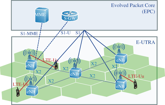
Figure 2.5 E‐UTRAN architecture.
The radio interface shows significant differences to the preceding UMTS. Multi‐user access of UMTS is based on WCDMA, using fixed 5 MHz carriers, while LTE is using Orthogonal Frequency‐Division Multiple Access (OFDMA) in downlink (DL) and Single‐Carrier Frequency‐Division Multiple Access (SC‐FDMA) in uplink (UL) as multi‐user access with scalable carrier bandwidth between 1.4 and 20 MHz. For spectral efficiency reasons, the tight frequency reuse of one has been kept in LTE irrespective of missing SHO capability resulting in considerable cell edge interference and strong impact on cell edge throughput and on timing of mobility management. Since the target cell identified for handover becomes the dominant interferer, very accurate timing of the cell change is crucial. And since radio conditions are different for each cell edge, mobility robustness optimization (MRO) was one of the first SON use cases standardized in LTE.
SON was introduced with the very first LTE standard release (3GPP Rel. 8), starting with features like Automatic Neighbour Relation (ANR), Automatic Physical Cell Identifier (PCI) assignment and Inter‐Cell Interference Coordination (ICIC). ICIC is a good example of more complex network configuration: the need for sophisticated ICIC resulted from choosing OFDMA to enhance spectral efficiency while keeping frequency reuse of one.
More network optimization related SON features like Coverage and Capacity Optimization (CCO), Mobility Load Balancing (MLB) and as discussed above MRO to accomplish a cell‐pair border individual handover timing optimization were introduced with following 3GPP Rel. 9, and more followed in the later releases showing that the network management and configuration becomes more and more complex with local and momentary adaptation which can only be accomplished by means of automation and self‐organization.
2.3 Network Evolution – Towards Cloud‐Native Networks
The mobile network evolution can briefly be summarized as follows: The 2G GSM technology enabled voice communication to everyone and everywhere by means of a circuit‐switched core network, supported roaming, and provided increased capacity compared to the analogue system of 1G. Since the year 2000, GPRS and EDGE, as well as 3GPP Rel. 99 (3G), supported both circuit‐switched voice services as well as packet‐switched data services.
3GPP Rel. 8 and 3GPP Rel. 10 (4G) have introduced a further design break by being a fully IP‐based system. They feature a flat, scalable architecture designed to manage QoS for high‐throughput services (mobile broadband). All services are packet‐switched and no longer circuit‐switched. The IP Multimedia Subsystem (IMS) provides a fully Session Initiation Protocol (SIP)‐based control architecture.
For 5G, the technology evolution to cloud services has motivated the next major review of the network architecture. In the design of 5G, the 4G CN functionality, comprising rather monolithic network elements (such as, MME), has been further decomposed into smaller functions. Moreover, a service‐based interface (SBI) design has complemented the traditional reference points between network functions. Before the details of the 5G system architecture are described in Section 2.4, this section will elaborate on the underlying technologies that will facilitate a transformation to cloud‐native mobile networks.
2.3.1 System‐Level Technology Enablers
Traditionally, telecommunication applications were designed and operated as proprietary solutions of tightly coupled hardware and software. Yet, the global development in Communication Service Provider (CSP) networks shows a shift from traditional voice and message services to web‐centric data services. This fundamentally changes the architecture of mobile networks. Most of today's data services rely on cloud technologies which have been established in the IT industry over the last decades and helped to reduce costs, increase efficiency, improve business agility, and enable new business models. CSPs are looking for similar benefits by evolving their infrastructure towards cloud‐native mobile networks:
- Increased agility in introducing new services: the traditional delivery model required months from ordering to delivery, but the telco cloud allows resources for new functions to be available within minutes. Self‐service interfaces and deployment automation allow rapid introduction of new services. So CSPs can quickly test new services and remove them with low cost if they do not fulfil expectations. Finally, ‘pay per use’ models can be supported more easily.
- Reduced hardware complexity: Hardware consolidation and commoditization allows the same hardware to be shared between functions of different generations or in different phases of their lifecycle.
- Operational efficiency: Through unified infrastructure, a single set of operations, administration, and maintenance (OAM) capabilities enables management of all VNFs. Consequently, higher levels of automation in service and network operations can be achieved.
Cloud service models outline how MNOs or, more generally CSPs, can evolve their networks towards providing cloud‐based and web‐centric service offering. The three basic cloud service models, Software as a Service (SaaS), Platform as a Service (PaaS) and Infrastructure as a Service (IaaS), are shown in Figure 2.6 and compared with a traditional ‘on‐premises’ deployment.

Figure 2.6 Cloud service models – technology mapping [10].
SaaS is the type of cloud service with the highest level of abstraction. It enables users to connect to and use cloud‐based applications, e.g. over the worldwide web. Exemplary SaaS offerings include Salesforce, Google's Apps and Gmail, Microsoft's Office365, Cisco's WebEx, or Dropbox.
PaaS operates at a lower level of abstraction and usually comes with a platform on top of which software can be created and run. One of the benefits of this model is that all applications built using the platform tools PaaS can exploit the platform runtime services, such as scalability, high‐availability, and multi‐tenancy services. Examples include Google App Engine, Microsoft (Azure) Service Fabric, or RedHat OpenShift.
IaaS provides users access to computing, networking, and storage resources such as servers, I/O ports, and databases. Clients use their own platforms and application software within an IaaS infrastructure. Examples include Amazon Web Services, Microsoft Azure, Google Compute Engine, OpenStack, or VMware vCloud.
From the MNO perspective, the two initially relevant cloud service models comprise IaaS and PaaS, that correspond to different phases for moving mobile networks evolving networks towards a telecommunication cloud [11], cf. Figure 2.7.

Figure 2.7 From traditional to cloud‐native telecommunications networks [11].
Many telecommunication operators currently find themselves amid the first phase, where virtualized networks achieve a strict separation of software‐based functionality from the underlying general‐purpose hardware by introducing a virtualization layer (e.g. hypervisors). For this transitive phase, which roughly corresponds to adopting the IaaS model, many vendors have converted their existing products into software versions able to run in a cloud environment at relatively low cost without great impact on the product architecture and functionality. The goal has been to remove vendor‐specific hardware and replace it with commodity IT hardware. However, for many NFs, this has proven to be quite inefficient and therefore required some performance optimizations (e.g. Intel Data Plane Development Kit ‘DPDK’) which again introduced hardware dependencies.
To fully harvest benefits and opportunities of the telco cloud, a system and product architecture transformation is required. Therefore, the second phase increasingly applies the design principles for cloud‐native applications to mobile networks functions. The rather monolithic NFs and telco applications are decomposed into smaller building blocks which will not only use IaaS but are developed and operated using higher‐level services and abstractions offered by a PaaS model. The network infrastructure as a whole evolves towards a set of platforms that offer automated and unified approaches to manage and operate applications. Exemplary platform services include procedures such as state management, resource scaling, load balancing, and similar application agnostic operations, thus relieving the telco application from these tasks. The most important differentiators between virtualized and cloud‐native networks are summarized in Table 2.3.
Table 2.3 Comparison of virtualized and cloud‐native networks.
Source: Adapted from [12].
| Characteristic | Virtualized networks | Cloud‐native networks |
| Level of automation | Manual operations; limited work‐flow/script‐driven automation | Extreme automation, model and policy‐ driven, ‘post DevOps’ |
| Investment strategy | Investment driven by standard refresh cycles | Investment driven by new business models, e.g. digitization of service delivery, new novel 5G/IoT service |
| Deployment characteristics | COTS + hypervisor + VNF (often single vendor) with limited orchestration capabilities | Multi‐vendor, horizontal, interoperable cloud components |
| Key technology components | COTS servers, Linux, hypervisors, OVS/VPP, OpenStack | PaaS, machine learning, hyper‐converged servers, compact DCs (e.g. edge clouds), hardware acceleration |
| Modularity | Handful of VNFs (limited scaling) | Dozen to hundreds VNFs or containers (dynamic, ephemeral networks) |
| Design and operation methodology | Software design mainly based on physical devices characteristics; reliability/redundancy/recovery schemes (frequently) part of application software | Software design built based on cloud principles; cloud reliability/redundancy/recovery mechanisms are provided by platform services |
2.3.2 Challenges and Constraints Towards Cloud‐Native Networks
While the long‐term shift towards cloud‐native networks must be acknowledged, it is important to recognize the constraints of currently available commercial off‐the‐shelf (COTS) infrastructure components. Many telco applications, such as, delay‐sensitive RAN functions, often have more challenging and diverse performance requirements than web‐based IT applications. These must be considered when designing cloud‐native telco networks, the key considerations for cloud‐native mobile networks being:
- Mix of services and requirements: Traditional telco services like voice require low and almost jitter‐free latency, but limited throughput and to be considered telco‐grade, they require 99.999% availability [13]. In addition, 5G networks aim at providing telco services to vertical markets for applications such as Industrial Internet of Things (IIoTs), Industry 4.0, smart grid, or car‐to‐car communications. These require e2e connectivity concurrently fulfilling high throughput, low latency, low jitter, and high reliability [14,15]. Cloudified systems have yet to prove the capability to fulfil such demanding requirements at large scales. As such, networks may continue to mix of legacy and telco‐cloud implementations.
- Network Function Virtualization (NFV): Purely software‐based telecom functionality shall run on non‐proprietary, commoditized hardware, but specific functionality continues to rely on specific hardware, e.g. for performance reasons. Evolution to first virtualization and then cloud‐native implementation remains challenging and,in some cases not even possible. IaaS model as adopted in IT must be complemented with a dedicated cloud platform and classical network management for legacy systems.
- Programmability and dynamic reconfigurability of mobile networks: Software‐defined networking (SDN) splits NFs into the decision logic hosted in a control application and the controlled NF in the network that executes the decision. This decouples the control application from the controlled NF, allowing, for example, full separation of the control and the forwarding function within the gateway and hence more flexible service chaining. Another example comprises SON functions that can dynamically optimize and reconfigure RAN and transport functions for better network utilization.
- Cloud‐native radio access: The RAN is a particularly challenging environment for NFV and cloud implementations, due to strict real‐time requirements and latency constraints of wireless communication. The RAN will continue to require a distributed topology, with dedicated hardware to support signal processing in the base stations. This topology inherently limits the expected benefits in terms of both statistical multiplexing and improved redundancy levels without significant additional deployments. On the other hand, cloud RAN deployments are frequently accompanied by the introduction of Multi‐access Edge Computing (MEC). Many applications, services, and contents may benefit from being executed at the access network.
- End‐to‐end management and orchestration: NFV and, later, cloud‐native networks were expected to exchange application‐specific and frequently proprietary hardware with less expensive commodity components that would harmonize and thus reduce the operational effort for infrastructure management. Initially however, NFV has instead increased the operational effort by adding an extra stack of functions for orchestration and lifecycle management (LCM) of virtualized resources, namely the ETSI NFV MANO functions NFV Orchestrator (NFVO), VNF Manager (VNFM), Virtualized Infrastructure Manager (VIM). A further evolution of NFV MANO has defined the interfacing with the traditional 3GPP OAM functions, i.e. Element and Domain Managers as well as Operation Support Systems (OSSs), cf. Figure 2.8. It is the next evolutionary step that will achieve the seamless integration of LCM and FCAPS procedures through related industry efforts such as the Linux Foundation's Open Network Automation Platform (ONAP) project or ETSI's Zero‐touch Network and Service Management (ZSM) specifications.

Figure 2.8 ETSI NFV MANO reference architecture.
Source: Adapted from [16].
2.3.3 Implementation Aspects of Cloud‐Native Networks
In cloud environments, microservices provide a scalable and efficient means to enable delivery of confined functionality as independent software building blocks which can be upgraded separately and in more frequent and smaller steps, e.g. continuous integration, delivery, and deployment. As a specific realization of service‐oriented architectures (SOA), microservices expose well‐defined interfaces to allow for lightweight service discovery, composition, and consumption, for example, the 5G Access and Mobility Management Function (AMF) could be further separated in smaller sub‐functions like UE registration, mobility management, etc.
In addition to microservices, a cloud native system supports the implementation of stateless applications that can scale without the need to transfer, e.g. session context information across processing units. In such implementation architectures, session context states are kept in an external database that is accessed by all micro‐services. This is realized by a so‐called Shared Data Layer (SDL) architecture that splits the data storage, both subscriber and session data, from the service logic enabling stateless virtualized network functions (VNFs). The basic principle is depicted in Figure 2.9. This means that VNFs no longer need to manage their own data and will only run the required business service logic, making them easier and faster to develop [17]. As outlined above, historically, the 3GPP network architecture has been composed of self‐contained network elements, each element storing and processing subscriber and service data. With the increase of subscribers and the demand for supporting new services and functions, this design faces scalability issues. Initial solutions, including standalone NFV, comprised scaling up individual network elements, which added complexity and limited optimization possibilities. Therefore, the shift to truly cloud‐native system design has to follow.

Figure 2.9 Concept of the shared data layer.
The heterogenous compute, I/O networking, and storage capabilities of a telco cloud infrastructure are distributed over numerous nodes and need to be interconnected on demand. The Smart Network Fabric is a multi‐layer, scalable, and dynamically reconfigurable IP/optical cloud interconnection to seamlessly process and transport data according to the service requirements. It connects central, metro, and edge nodes of public mobile network operators, datacentres of Internet service and cloud computing providers, private nodes in enterprises or residential homes, and hub nodes of the Internet backbone.
To ensure both efficiency and reliability, the scaling and allocation of resources amongst clouds needs to be dynamic. The result is a unified cloud infrastructure that is dynamically distributed over a mesh of locations interconnected by means of the Smart Network Fabric. Figure 2.10 illustrates the Smart Network Fabric connecting edge, metro, and central clouds. While IP continues to be the enabling convergence protocol, Segment Routing could be a potential solution for providing a ‘hybrid control plane’, i.e. exploiting the efficiency of centralized path optimization and retaining the scalability of distributed routing.
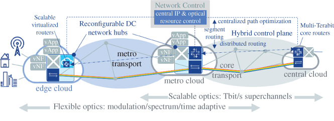
Figure 2.10 Key principles of the smart network fabric.
Source: Adapted from [18].
The outlined technology enablers and their role in building a cloud‐native mobile network have had a major impact on the design of the 3GPP 5G system Rel. 15 and continue to shape the design of upcoming releases. This is described on the following sections for both the overall 5G system and the associated RAN.
2.4 Multi‐Service Mobile Communications
Mobile networks of the fifth generation are becoming an important enabler for the ongoing digitization of business and daily life and the transition towards a connected society. Services in high priority fields for society (e.g. education, health, government services) or business areas (e.g. smart grids, intelligent transport systems, industry automation) will rely on a versatile mobile network infrastructure. In these areas, machine‐type devices will increasingly contribute to mobile traffic, introducing highly diverse characteristics and requirements significantly different from today's dominant human‐centric traffic. Hence, 5G networks must combine high performance with the support for service‐specific functionality. For economic reasons, a common infrastructure platform that is shared amongst multiple communication services is needed. 5G networks will exploit the so‐called ‘network slicing feature’ to enable multi‐service and multi‐tenant capable systems.
2.4.1 Multi‐Tenant Networks for Vertical Industries
For 5G development, three fundamental communication service classes have been introduced, (i) massive broadband, characterized by very high data rates, (ii) critical machine‐type communications (cMTCs), also referred to as ultra‐reliable, low‐latency communications (URLLCs) and characterized by low latency and high reliability, and (iii) massive machine‐type communications (mMTCs), characterized by highly scalable and cost‐efficient network operations. A detailed analysis on the requirements per service class is given in [14], For functional requirements, however, multi‐service mobile networks shall incorporate numerous capabilities, some of which are already supported by the EPS including:
- Service‐specific traffic detection and network performance monitoring rules;
- Service‐specific network control: settings for QoS, mobility, security, etc. can be dynamically derived based on detected services and network context, for example, mobility management configurations may be specified for UE type and class, UE mobility pattern, the detected service characteristics in terms of reliability and continuity, and the capabilities of the radio access technology (RAT);
- Adaptation of NF configuration to enable service differentiation, i.e. NF selection, placement, and configuration is adapted to the supported communication service. For instance, virtualized NFs may be located at the central cloud for services with relaxed latency requirements or placed at the network edge for low latency services. Furthermore, multi‐connectivity may be configured for increased throughput for broadband services, or it could be configured to increase reliability for URLLC services.
For multi‐tenancy support, each tenant's business requirements, service level agreement (SLA) policies, and resource isolation requirements, need to be considered:
- Network resources such as networking capacity and storage processing are divided into different pools for different resource commitment (sharing) models.
- Different resource management policies are defined per tenant. In particular, each tenant can require different QoS levels which may be fulfilled by means of, for example, particular NF chains, function configurations, or radio scheduling policies.
- Tenants, depending on their level of expertise, may request different service monitoring and configuration capabilities via a GUI or APIs. Therefore, selected system functionality may be exposed to allow tenants supervision and control of their communication service in a limited fashion.
- Network operators and infrastructure providers require tools and processes to prioritize tenants and their respective services. As mediator and admission controller, they need to prioritize and admit tenants' service requests according to an objective function that reflects overall operator targets and utility.
2.4.2 5G System Architecture
3GPP foresees several deployment options for the fifth generation (5G) of mobile networks, the so‐called ‘standalone’ (SA) option and several variations of ‘non‐standalone’ option. In SA (‘Option 2’), 5G UEs use 5G New Radio (NR) for both user plane and control plane traffic. gNBs connect to the 5G core network (5GC), which could also interact with legacy (e.g. LTE) base stations. Options 3 and 7 combine a mixed 4G–5G RAN with either 4G or 5G CN. 5G NR is used as an additional carrier for user plane traffic whereas control plane traffic is handled by LTE. In NSA option 3 ‘LTE assisted, EPC connected’, a 4G core network is used, while option 7 ‘LTE assisted, 5GC connected’ assumes a 5GC. Both options have two variants: either gNBs directly connect to the core network or via the LTE base station (note: the latter case is not depicted in Figure 2.11). Option 4 is similar to option 7: control and user plane traffic is now handled by 5G NR while LTE only serves as an additional carrier for user plane traffic. Table 2.4 summarizes the major characteristics of SA and NSA.

Figure 2.11 Selection of 5G deployment options.
Table 2.4 Comparison of 5G NR standalone and non‐standalone options.
| Standalone (SA) | Non‐standalone (NSA) | |
| NR radio cells | Directly used by 5G device for control and user planes | 5G used as secondary carrier, under the control of LTE eNB (‘Option 3’ or ‘Option 7’) |
| Choice of core network | 5G core network (5GC, ‘Option 2’), which may also anchor inter‐RAT mobility with LTE | 4G EPC (‘Option 3’) or 5GCN (‘Option 7’) |
| CSP perspective | Simple, high performance overlay | Leverages existing 4G deployments |
| Network vendor perspective | Independent RAN product | Requires tight interworking with LTE |
| End user experience | Peak throughput set by NR; Dedicated low latency transport | Peak throughput is up to the sum of LTE and NR; Latency impacted when routed via LTE |
The substantial increase of mobile broadband traffic volume as well as the objective to support a wide range of diverse services for vertical industries requires a flexible, elastic, and programmable network. To achieve this objective, 3GPP specified a new system architecture for 5G. The 5GC is a cloud native CN, that leverages on NFV and SDN as the enabling technologies for abstracting network functions from the underlying hardware.
In terms of architecture, the 5GS is an evolution of the 4G system. It introduces distributed User Plane Functions (UPFs), formerly S‐GW and P‐GW, and maintains Control and User Plane functions Separation (CUPS). Several use cases will benefit from having flexible UPF deployment options, depending on the communication service requirements. For example, while low latency services require UPFs close to the radio, the best option for basic Internet access continuous to be rather centralized UPFs. In the control plane, the 5GC further decomposes 4G functions, e.g. by introducing separate functions for Session Management (SMF) and Access and Mobility Management (AMF). In practice, this means that smaller software components can be deployed independently (e.g. as microservices), configured, and scaled to support the cloud‐centric operations and the LCM model of the 5GS.
3GPP Rel. 15 system architecture specifications [19–21] describe the 5GC architecture in two ways with the same set of network functions: (i) a reference point‐based architecture, reflecting a traditional 3GPP architecture (not shown here), and (ii) a service‐based architecture (cf. Figure 2.12) which is fully aligned with cloud principles. Option 2 reflects the ‘Network Cloud OS’ concept where network services are ‘composed’ using a library of functions hosted in a cloud and ‘chained’ together to create the end‐to‐end service. The key components of the 5GC architecture include:
- Access and Mobility Management Function (AMF): The single control plane function that terminates the interface from the access networks and from the UE, manages access control and mobility, and plays a key role in network slice functionality by serving all slices a UE is accessing
- Session Management Function (SMF): This establishes and manages sessions for all access types according to the network policy. In EPC, this functionality is spread across the MME and S/PGWs
- User Plane Function (UPF) is equivalent to the user plane of the EPC serving/packet data network gateway (S/P‐GW), but is enhanced to support flow‐based QoS and a new session and service continuity mode that allows a make‐before‐break function for URLLC. Operators can deploy multiple UPF instances in distributed and centralized locations, according to service type for example
- Policy Control Function (PCF) delivers a common policy framework by exposing policies as a service that are consumed by any authorized client. Besides QoS and charging, it supports network slicing, roaming, and mobility management policies
- Authentication Server Function (AUSF) provides a common authentication framework for all access types
- Unified Data Management (UDM) stores subscriber data and profiles, as is done by the HSS or HLR. It is envisioned that it integrates subscriber information for both fixed and mobile access in 5GC
- Network Repository Function (NRF) provides new 5G functionality. NRF provides registration and discovery functionality enabling network functions and services to discover each other and communicate directly via open APIs
- Network Exposure Function (NEF) supports the external exposure of capabilities of network functions, such as, monitoring capability, provisioning capability, and policy/charging capability
- Unified Data Repository (UDR) represents a common backend for the UDM, NEF, and PCF
- Network Slice Selection Function (NSSF) provides the new 5G functionality of assigning UEs to network slice instances
- Unstructured Data Storage Function (UDSF) provides the new functionality allowing control plane functions to store their session data and to become session stateless
- Non‐3GPP Interworking Function (N3IWF) is a 5GC function for the integration of the stand‐alone untrusted non‐3GPP access to the access agnostic, universal core. N3IWF terminates IPSec and IKE v2 and exposes towards the common core N2, N3 similar to the RAN.

Figure 2.12 Architecture (service‐based view) of the 5G system.
Procedures as well as the Policy and Charging Control Framework for the 5G system are described in [20,21], respectively.
Figure 2.12 depicts the service‐based architecture (SBA) design. It comprises a major change to the reference‐point‐based design of previous generations and is also expected to be the more relevant deployment option.
2.4.3 Service‐Based Architecture in the 5G Core
The 3GPP SBA largely follows SOA software design principles. SOA‐based systems comprise functions that offer services that are exposed to service consumers through a well‐defined interface. The high level of modularity allows flexible composition of complex services by mixing and matching fine‐grained services. The Open Group determines four defining properties of a service [22]: (i) It logically represents a business activity with a specified outcome; (ii) it is self‐contained; (iii) it is a ‘black box’ for service consumers; (iv) it may be composed of other services.
The SBA of the 5GC defines services that any service consumer with proper authorization can use. A service consumer can consume multiple services and it can create its service offerings that are exposed to other service consumers. The relationship between service consumer and service producer is not fixed by the type of logical entity, as was the case of the earlier used reference point‐based architecture versions, where reference points between logical entities were defined together with the protocols. Instead, in SBA service, consumers do not have static relationships with the service instance they are using, but a service consumer discovers those services it needs by a service discovery procedure offered by NRF. This service‐based approach results in more flexible and dynamic architecture where new services can be introduced without impacting other service producers or service consumers. Only a new service interface needs to be defined and made available to the needing service consumers. The approach matches well with the cloud computing concept where the location and capacity of a service can change dynamically.
In the 3GPP Rel. 15 SBA model, services are implemented by Network Functions (NFs) and exposed through SBI. In contrast to a reference‐point‐based architecture, an NF exposes interfaces that are neither bound to a specific reference point nor to a specific consumer. Rather, the binding takes place through service discovery, selection and well‐defined authentication and authorization means. Each of the services provided by an NF exposes a separate SBI for any service consumer to use. For example, the AMF is defined to contain and offer four different services to any authorized service consumer, typically to NFs such as SMF and Policy and Charging Function [21]. Any of the following AMF services, can be upgraded without impacting other interfaces and their consumers [23]:
- Namf_Communication service used to communicate with the UE and the RAN
- Namf_EventExposure service providing notifications based on mobility events
- Namf_MT Service which provides paging
- Namf_Location service which is a servicing positioning request.
Each of these services are self‐contained and their life cycle can be managed separately.
The roles of NF service producer and NF service consumer closely follow the traditional client‐server model of the Web‐services in their interaction with each other. The service APIs are defined by using REpresentational State Transfer (REST)‐ful [24] service operations where standard HTTP‐methods are applied whenever possible. According to the REST model, the application‐level state is contained in the responses to the requests. Based on the state in the response message from the service producer, the service consumer learns how to interact with the service producer in subsequent transactions. The service producer doesn't need to maintain any state for a given service consumer. The service consumers and producers use the HTTP‐protocol to exchange the representations of resource states and operations on them. A URI consist of Path‐part and Query‐part [25]. All SBI APIs and services are defined by the supported resource URI with possible parameters and by the allowed HTTP‐operations (e.g. GET, PUT, POST, PATCH, etc.) against the resources.
All service producers register and deregister their services with the NRF. Service consumers use the services of NRF to discover and select service instances they would like to consume. NRF authorizes a service consumer to access and use service instances as part of the service discovery process. NRF also provides system level services such as monitoring the load situation of the services and their liveliness. Therefore, NRF is the most critical and central component of the whole SBA.
Figure 2.13 shows an example how the NFs of the 5GC SBA interact with each other. In the depicted scenario, an AMF contacts an SMF to create a context for a UE for subsequent requests to establish PDU sessions. This may have been triggered by NAS‐signalling at the time when UE registered to the network. At step 1, the AMF needs to discover an SMF instance that has capacity to serve the UE. It sends a service discovery message to NRF in a form of ‘HTTP‐GET’ message with proper parameters. As a response, the NRF returns a list of matching SMF instance identifiers if there is more than one SMF instance available in the ‘200 OK’ message at step 2. The AMF completes the instance selection by using the list of possible SMF instance identifiers and sends in a ‘POST’ message containing information about the UE to the selected SMF at step 3. If the context creation was successful, the SMF responds with ‘201 Created’ message to the AMF at step 4.
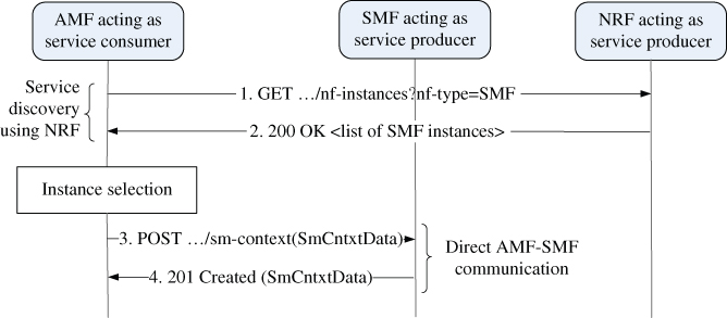
Figure 2.13 Example of SBA interactions between AMF and SMF.
2.4.4 5G RAN
The design of the fifth‐generation radio network architecture had to consider a diverse set of requirements, both functional as well as performance related, making it a challenge for system design and standardization [26]. These – partially interdependent – main requirements are:
- As far as possible, integration of new radio (NR) and E‐UTRA into a common architecture allowing seamless handover and interworking between both RATs
- Allow for flexible centralization of radio functions depending on the infrastructure capabilities and deployment scenario
- Scalability for different use cases and scenarios ranging from ultra‐broadband to massive IoT
- Support for virtualization and softwarization of RAN functions.
The first requirement in this list – integration of NR and E‐UTRA – has an impact to virtually all aspects of the architecture as it is eminent in the different options for stand‐alone (SA) and NSA system architecture, cf. Table 2.4. For the RAN architecture, the main impact is the integration of RAN nodes with NR and E‐UTRA air interface via common interfaces towards 5GC, and between RAN nodes, as shown in Figure 2.14. Similar to the LTE‐A, NG‐RAN defines a ‘flat’ architecture (see [27,28]) where RAN nodes are interconnected via Xn interface and connected to the 5GC via the NG interface, similar to the 4G EPS. In NG‐RAN, a gNB is a RAN node hosting NR radio, while an ng‐eNB hosts E‐UTRA radio. The RAN‐level interface between different RATs enables a variety of interworking options, including:
- Hand‐over between NR and E‐UTRA with user‐plane data forwarding in RAN
- Dual Connectivity (DC) between NR and E‐UTRA, with gNB or ng‐eNB as Master Node (MN) or Secondary Node (SN)
- E‐UTRA‐NR co‐existence including supplementary uplink (SUL), where a single TDD band is shared by LTE and NR for uplink
- ANR between NR and LTE.

Figure 2.14 NG‐RAN architecture [27].
The common RAN‐CN interface enables access‐agnostic core network as far as possible, reducing the need for RAT‐specific functions. Flexible centralization, scalability, and virtualization is supported by means of a logical split architecture of RAN nodes, which allows more independent scaling and instantiation of UPFs as well as dislocated placement of RAN functions. NG‐RAN Rel. 15 [29,30] defines a logical fronthaul interface (F1‐C and F1‐U, cf. Figure 2.15) for ‘higher‐layer’ split and a split between control‐plane and user‐plane. Higher‐layer split in this context, denotes a split between Packet Data Convergence Protocol (PDCP) and Radio Link Control (RLC) protocol, but still in OSI layer 2. Lower‐layer split options denote options where the split is in the physical layer. Those options are not defined by 3GPP, but. by CPRI forum, for example, as eCPRI which specified a transport for an intra‐PHY split point [31]. This option has a significantly lower bandwidth requirement than the original CPRI split point designed for quantized symbol transport.
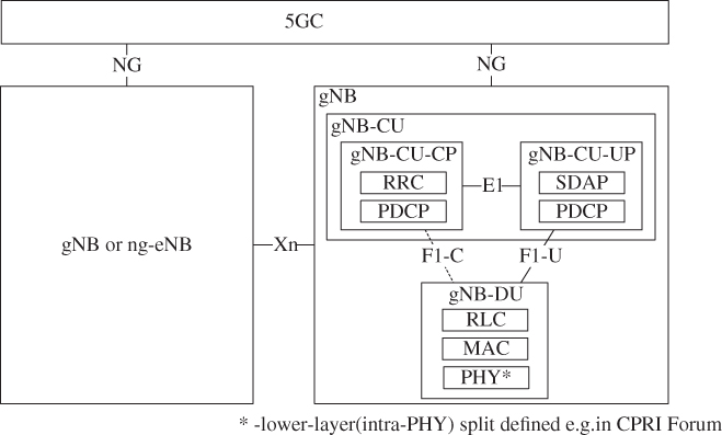
Figure 2.15 Logical split RAN architecture [28].
It is important to note that RAN logical split is transparent to the network and to the UE. This allows realization of RAN nodes both as monolithic (and distributed) as well as centralized (but with fronthaul split) deployments [26], as well as instantiation of RAN functions according to service or network slice requirements.
The split logical RAN architecture of NG‐RAN Rel‐15 is shown in Figure 2.15. The F1 logical interface interconnects the Centralized Unit of a gNB (gNB‐CU) and the distributed unit (gNB‐DU). It is further distinguished in F1‐C for control plane and application protocol, as well as F1‐U for user‐plane data. Furthermore, the E1 control interface provides CP/UP separation in the case of an existing F1 interface.
One gNB‐CU‐CP can be associated to several gNB‐DU and gNB‐CU‐UP entities, allowing independent scaling and redundancy for user plane. There are some limitations on the number of logical entities possible within a gNB, as shown in Table 2.5.
Table 2.5 Scaling limits of gNB logical entities.
| Logical entity | Hosting entity | Maximum allowed logical entities within hosting entity | Limiting element | Source |
| gNB‐CU | gNB | 1 | By definition | [28] |
| gNB‐DU | gNB | 2^36 | gNB‐DU ID | [32] |
| gNB‐CU‐CP | gNB‐CU | 1 | By definition | [28] |
| gNB‐CU‐UP | gNB‐CU | 2^36 | gNB‐CU‐UP ID | [33] |
| NR cell | gNB | 1 024–16 384 | NR cell identity and gNB ID | [34] |
| NR cell | gNB‐DU | 512 | maxCellIngNBDU | [32] |
| TNL association | gNB‐CU | 32 | maxNoOfTNLAssociations | [32] |
2.4.5 5G New Radio
The new 5G RAN (denoted as ‘NR’) features several key technology components which allow fulfillment of the quite challenging and diverse requirements on latency, reliability, and throughput. One of the main features of NR is the extremely flexible support for carrier frequencies from 450 MHz up to 40 GHz, with a supported channel bandwidth in the range of 5 up to 400 MHz. The higher frequency ranges, in combination with carrier aggregation enable configurations with up to 1200 MHz aggregated channel bandwidth, allow 20 Gbps throughput for eMBB to reach use cases. The lower frequencies are ideal for wide coverage scenarios, potentially with building penetration such as required for massive IoT. Table 2.6 lists a few of the most important NR features and their benefits. This section elaborates on selected features in more detail.
Table 2.6 Selection of NR features and their benefits.
| Feature | Benefit |
| Usage of spectrum above 6 GHz | 10× to 100× more capacity |
| Massive MIMO and beamforming | Higher capacity and coverage |
| Lean carrier design | Low power consumption, less interference |
| Flexible frame structure | Low latency, high efficiency, future‐proofness |
| Scalable OFDM air interface | Address diverse spectrum and use cases |
| Scalable numerology | Support of multiple bandwidth and spectrum |
| Advanced channel coding | High robustness for short blocks, large data blocks with low complexity |
This flexibility is enabled by a scalable carrier numerology with sub‐carrier spacing ranging from 15 kHz for lower channel bandwidth up to 120 kHz for 400 MHz channels. In total, a sub‐carrier spacing in the set of {15, 30, 60, 120} kHz is supported for data channels, where the scaling with 2n · 15kHz allows for efficient FFT processing for the OFDM symbol generation as well as compatibility with LTE subcarrier spacing (15 kHz).
NR supports time‐slot durations between 0.125 and 1 ms depending on the sub‐carrier spacing and the corresponding OFDM symbol length in time. One slot always comprises 14 symbols, meaning that one radio frame of 10 ms length can comprise up to 160 slots for higher sub‐carrier spacings. To meet ultra‐low latency requirements, NR further enables flexible configuration of downlink and uplink slots within one frame.
5G NR needs to support different type of services in a radio cell, meaning that the frame design needs to be sufficiently flexible to support configurations for 0.5 ms latency of layer 2 packets on the one side, but on the other side longer and more power‐efficient configurations for low‐complex, massive IoT devices. This design objective is achieved by introducing bandwidth parts (BWPs), which serve as a self‐contained structure in the resource grid which enables different configurations of sub‐carrier spacing, slot formats, and correspondingly, mapping to quality of service requirements within a single carrier.
Figure 2.16 illustrates the basic principle of the flexible frame structure in 5G NR. Each of the different parts of the frame annotated with different use cases could be configured such that efficiency, e.g. in terms of reaching QoS KPIs, resource utilization, device power consumption, etc. is optimized. Devices which are configured for BWPs only need to decode common control information, and control information for the corresponding BWP. This feature can be also be applied to the end‐to‐end concept of network slicing, such that BWPs and corresponding configurations are associated with one network slice or potentially several slices. It should be noted that the flexibility comes with a price related to schedule and implementation complexity in the network. On the device side, low complex design would require conscious choices of configuration options which need to be agreed by industry stakeholders.

Figure 2.16 Flexible frame structure in 5G NR.
A further key pillar in the 5G NR framework is the extensive support of massive MIMO and beamforming. Massive MIMO in the context of NR denotes support of antenna arrays with a large number of controllable antennas (e.g. 32 controllable transmit antennas [32 Tx], or more). Beamforming denotes a specific transmit/reception strategy where massive antenna panels are used to form directional beams with high antenna gains. This is specifically required to overcome the challenging propagation characteristics of higher frequencies above 6 GHz. Nevertheless, beamforming is also useful for frequency deployments below 6 GHz, e.g. in the case if LTE carriers in 1.8 GHz bands should be complemented, at the same site, with NR resources in 3.5 GHz bands. In addition to the coverage advantages of beamforming, higher‐order spatial multiplexing can be applied by re‐using the same time‐frequency resources in different directional beams.
Three types of antenna array architectures are supported. The one most capable in terms of flexibility and granularity of beams is digital baseband beamforming. In this case, each antenna element or antenna port has a dedicated transceiver unit which can be controlled in terms of gain and phase individually. This allows dynamic frequency‐selective beamforming where different beam patterns can be generated for different frequency ranges, thus allowing the combination of spatial, time, and frequency multiplexing. However, digital beamforming is subject to high power consumption and cost characteristics when bandwidth increases.
As a further concept, analogue beamforming denotes an architecture where beam patterns are generated by adapting Tx/Rx weights in RF (i.e. in the analogue domain at the antenna). This architecture allows the implementation of (semi‐) static beam patterns with pre‐defined Tx/Rx weights which can be switched at different time instances. For example, beam switching is used to generate a ‘rotating’ beam pattern in time with one directional high‐gain beam for coverage optimization. For control channels and channel acquisition, a wide coverage beam can be generated. In this architecture, only one transceiver unit is needed, reducing cost and complexity especially for high‐frequency scenarios.
Finally, hybrid antenna arrays combine digital with analogue beamforming. Several RF units are combined and controlled by a single transceiver unit, such that a limited number of beams/beam patterns can be generated at the same time, but with less granularity and flexibility than with fully digital beamforming. This enables CCO also in higher frequencies but with less complexity if, for example, up to eight transceiver units are supported.
From a network management and operational perspective, it is important to understand that each of the antenna array architectures require different sets of parameters and also exhibit different operational behaviours in terms of resource allocation, parameter optimization e.g. for mobility, and other management aspects.
5G NR is the first 3GPP Release where beamforming is an integral design objective of the air interface. For this purpose, NR provides a beam management framework to optimize performance using beamforming. Beam management consists of the following phases:
- beam indication, which helps the UE to select beams in uplink and downlink directions both for initial access and in connected state
- beam measurement and reporting, including reporting of suitable downlink and uplink beams for a UE to the network
- beam recovery for rapid link reconfiguration against sudden blockages
- beam tracking and refinement to optimize beam parameters at UE and gNB.
Beam management procedures are anchored mainly at MAC and PHY layers. However, cell level mobility is related to beam management in the sense that the same procedures are applied, but additionally the serving cell is changed and, possibly, a path switch for user plane data from the core network is performed.
Multi‐connectivity is one of the key features of NG‐RAN (including E‐UTRA and NR RATs), which is not only used for bandwidth aggregation and throughput enhancements, but also for reliability enhancements both on control‐ and user‐plane by duplicating packets on radio bearers anchored in physically disjunct locations. Multi‐connectivity in NG‐RAN is denoted as Dual Connectivity (DC – similar to LTE), but with more flexibility and capabilities. In general, DC user plane operation (traffic splitting, aggregating, duplicating, and discard) is anchored in the PDCP layer. The following types are differentiated according to the air interfaces involved and connectivity to the core network, following the standalone and non‐standalone architecture options described in Table 2.4:
- MR‐DC: A generic term for Multi‐RAT Dual Connectivity where air interfaces of the master and the secondary node are not the same
- NR‐NR DC (short: NR‐DC): Dual Connectivity where both radio nodes are gNBs hosting NR radio interfaces
- E‐UTRA‐NR‐DC (short: EN‐DC): Dual Connectivity where the master node is an LTE eNB connected to an EPC, and the secondary node is a gNB with NR air interface
- NR‐E‐UTRA‐DC (short: NE‐DC): Dual Connectivity where the master node is a gNB with NR air interface, and the secondary node is an ng‐eNB, i.e. an eNB with E‐UTRA (LTE) air interface connected to a 5G core
- NG‐E‐UTRA‐NR DC (short: NGEN‐DC): Dual Connectivity where the master node is an ng‐eNB, and the secondary node is a gNB.
In practice, the variants which will presumably gain the highest market relevance will be NR‐DC and EN‐DC since many NR deployments will start as a ‘capacity booster’ for an existing LTE network.
To enable URLLC services, 3GPP has also defined a set of features including:
- Robust channel coding and repetition for more reliable transmission
- shorter transmission time intervals down to 0.125 ms to achieve 1 ms overall latency over the air
- packet duplication on PDCP layer
- multi‐connectivity for increased reliability, including RRC diversity via signalling radio bearer (SRB) split
- flexible function placement with local breakout and edge computing
- HARQ enhancements, i.e. flexible and faster HARQ round‐trip time (RTT) as well as asynchronous and automatic HARQ
- MAC scheduling enhancements for reduced transmission latency, including pre‐reserved, restricted, and pre‐emptive schemes.
2.4.6 5G Mobile Network Deployment Options
Today, cloud‐based IT and, although to a lesser extent, telecommunications infrastructures are largely based on centralized topologies where users' traffic is sent to a small number of datacentres in a central place. This model is well suited for mobile Internet services and has the great advantage of keeping an operator's total cost of ownership (TCO) low.
However, there are several use cases that greatly benefit from having their application components closer to the user, i.e. placed in the access network. For example, many 5G use cases require low latency with round trip times of a few milliseconds, amongst them industry automation and tactile Internet services. Other use cases such as autonomous vehicles and drones benefit from minimizing V2X communication delay by placing applications closer to the user. In addition, transporting large traffic volumes to a central place, as some of content delivery network (CDN) use cases require, may cause transport bottlenecks. Those factors, low latency applications and proper scaling of CDNs lead to a paradigm shift in cloud architecture design.
Multi‐tier edge cloud deployments form the basis of the emerging infrastructure paradigm that features distributed datacentres at the edge of the network. Those edge clouds are located at different aggregation levels between the radio periphery and the core networks. The exemplary three‐tier network infrastructure (see Figures 2.1–2.4) consists of a very large number (100s up to a few thousands) of edge sites and a considerable number (up to 100) of aggregation sites, which are connected to a few (up to 10) large centralized datacentres. Such distributed edge sites create the basis for introducing flexible deployment of softwarized network functions, cloudified RANs, MEC platforms, e.g. [35,36], and related applications.
As outlined in Section 2.3, decomposition and hardware‐independent design of 5G applications allow for a flexible and adaptive commissioning of network functions in different locations of the network. Virtualized NFs can even be re‐located during operation with limited impact on performance. Figure 2.17 depicts an example of network evolution exploiting decomposition and flexible allocation of NFs, including both fixed and mobile access NFs. Those access NFs are decomposed into smaller software functions hosted on computation platforms in the edge clouds together with converged core network functions and relevant applications and services. Mostly cloud‐based centralized RAN and optical line terminal (OLT) functions of passive optical networks (PONs) are deployed in the edge cloud in high‐density areas, while more distant and moderately populated areas are served by small access hub locations containing real‐time (RT) baseband and/or OLT functions. Such flexible deployment options are essential to adapt to the foreseen traffic variations of 5G networks.

Figure 2.17 Network evolution exploiting flexible deployment options.
In a more detailed breakdown, Figure 2.18 differentiates four basic regions that span over six aggregation levels to form a topological view of 5G cloudified networks:
- The antenna site region usually hosts functions that are characterized by a tight coupling of software and hardware (physical network functions (PNFs)) due to performance reasons. PNFs are most commonly located at the antenna or RF premises site. However, they can also reside in other locations of the network infrastructure.
- The edge cloud region covers the peripheral sites with transport hubs and packet‐optical aggregation points, comprising the first two aggregation levels, ‘photonic backhaul’ and ‘metropolitan area networks (MANs)’. RAN nodes located rather close to the antenna site comprise a very limited amount of general‐purpose compute, storage, and networking hardware (e.g. NFVI resources) or application‐specific hardware (e.g. baseband units). At metropolitan‐level, depending on the deployed RAN split architecture, a single site has to process between 100 Gbps and several Tbps.
- The transport cloud region comprises medium‐sized transport hubs and datacentres at major aggregation sites of the network. It spans metropolitan area sites, the so‐called ‘regional optical domain’, and the ‘core’ aggregation level. For the latter, single sites must process approximately 10 Tbps of traffic.
- The central cloud region refers to a limited (typically a low double‐digit) number of large‐scale data‐centres. They comprise the sites of the optical core domain where total traffic volume can grow up to a few hundreds of Tbps.

Figure 2.18 Topological view of a large size mobile network infrastructure.
The adaptive decomposition, disaggregation, and (re‐)allocation of network functions to these regions, depending on the service requirements and deployment constraints, is a significant novelty over legacy networks. It allows realization of the same functional architecture by instantiating the network functions in different physical deployment scenarios, or even multiple deployment scenarios in parallel. For example, if multiplexing gains are exploited, a higher level of centralization is preferred, which is suitable for services such as eMBB. On the other hand, if traffic needs to be processed closer to the network edge, e.g. due to latency requirements or limited transport capacity, network functions can be executed in the edge cloud region. This more distributed deployment scenario can be useful for URLLC‐type traffic.
Beyond the flexible deployment of VNFs to multiple and varying cloud locations, a further factor impacting the mobile transport networks comprises the increasing number of small cell deployments in 5G when compared to earlier cellular network generations. Therefore, the overall backhaul and – depending on the used technology – the midhaul, i.e. the links between distributed units (DU) and centralized units (CU), will be more that branching and network topology become more interconnected, e.g. mesh network between the small cells, such that the number and overall length of links will dramatically increase. Second, 5G NR air interface will allow for far higher data rates. Together with the expected use of massive MIMO, this will dramatically increase the data rates on the fronthaul links between radio units (RU) and DUs.
In the era of 5G, mobile networks will undergo a fundamental change. Future RAN solutions will be deployed in a most cost efficient and agile way, serving any kind of clients' or end‐customers' service pattern needs (eMBB, URLLC, IoT) or mobile network densification. Traditional monolithic BTS/RAN deployment principles will gradually dissolve into more distributed ‘split RAN’ architectures (cf. Section 2.4.4), which will require a more sophisticated transport underlay, clearly beyond traditional backhauling.
It is expected that such split RAN architectures will first be applied more locally by decomposing and connecting BTS baseband unit (BBU) functions into separate entities of RUs, DUs, and CUs. However, in next RAN deployment stages, the decomposed BBU functions are supposed to be spread wider over a much larger deployment footprint, in any kind of (integrated) RU, DU, and CU assemblies (and combinations) between different RAN or central office (CO) locations and connected by means of an external transport network. Some mobile operators with fibre‐rich assets, particularly in the last miles, have already started these stages with first rollouts.
3GPP has defined certain RAN split categories [28], mainly
- between RUs and DUs, based on real‐time‐sensitive low layer split (LLS) options along with corresponding fronthaul connection profiles for the transport network
- between DUs and CUs, based on less time‐stringent (and less bandwidth‐hungry) high layer split (HLS) options, which use a midhaul‐type transport connection profile.
Each split category may have further detailed split options, e.g. 3GPP LLS options 8, 7.1, 7.2X, 7.3, or 6, each having its own benefits and drawbacks [37]. Lastly, split RAN options may have specific ways of implementation:
- DUs and particularly CUs can be further disaggregated into a control plane (CU‐CP) and several distributed user plane (CU‐UP) instances with new mid‐haul type interfaces, cf. Figure 2.15.
- Most recently, additional new RAN entities are envisioned to be introduced, like the RAN intelligent control (RIC) in ORAN specification work [38].
- Moreover, DUs and CUs can be implemented using either compact/bare‐metal or COTS/cloud driven approaches. The latter virtualizes native BBU functionalities into virtualised functions (vBBU).
In general, the entirety of transport connection profiles, including those for the new split RAN interfaces, are referred as x‐haul profiles, i.e. they combine traditional backhauling with the new mid‐ or fronthauling needs. For the different RAN deployment options, transport‐relevant KPI indicators include bandwidth, latency, or site distance.
Due to these developments, mobile traffic transport profiles on the backhaul, midhaul, and fronthaul will have to rely on a mix of transport technologies and deployment options. In some areas, due to cost reasons, backhaul of small cells will be based on wireless multi‐hop technology (microwave and millimetre‐wave in non‐access frequency bands) or even on self‐backhauling, thus reducing capacity in the access. However, in areas with higher traffic demand, a ‘fibre‐to‐the‐X’ (FTTX) optical wireline solution will be preferred, e.g. eCPRI [31].
Overall, these developments will lead to an increase in the number of transport connection points as well as the dynamicity of the topological adjustments. Hence, mobile traffic control and management planes need to be upgraded to technologies such as SDN to manage the rapidly changing traffic mixes and connectivity configurations.
2.5 Evolution of Transport Networks
Transport networks transfer bit streams between different types of accesses over varying distances. They form the underlying infrastructure of a communication network. Transport networks are structured into tiers as shown in Figures 2.18 and 2.19. The evolution of each of the hierarchy levels has been driven by very different capacity, reliability, and cost requirements of the network domains. The growing amount of bursty traffic patterns, transport network unification, and convergence has made packet‐based technologies preferable across all transport network hierarchies. Since transport networks are strategic and imply significant TCO expenditures, their renewal is mid‐ to long‐term oriented, with more gradual deployment steps than most other parts of the network infrastructure.
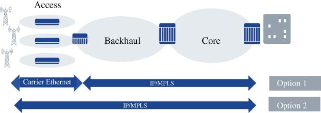
Figure 2.19 Carrier Ethernet and IP/MPLS options.
2.5.1 Architecture of Transport Networks
Access networks at the periphery (e.g. radio network, FTTX, PON, hybrid fibre‐coaxial [HFC], DSL, Ethernet) collect individual traffic flows from the end users and aggregate the traffic towards the backhaul networks. The topology of access networks is typically a star, a tree, or a chain that connects individual customer premises equipment (CPE) or base stations to a last mile(s) hub node that feeds the next level of the aggregation network. The number of equipment and links in the access network is very high in comparison to the other transport tiers. Link capacities typically vary from a few hundred kbps (e.g. IoT‐type devices) up to a few Gbps. Last miles access links may either be shared among access points (e.g. PON, cable, fibre ring) or have dedicated point‐to‐point connections to the user or customer premises. Consequently, the cost of physical deployments in the access network (such as deploying fibre ever closer to customers – ‘fibre deep’) is a dominant factor when considering upgrading the access.
The topology of higher transport tiers is based on rings that offer redundant paths in case of link or node failures. A traditional mobile backhaul network typically covers several aggregation switches or routers that connect to the access links. Here, packet‐based technology is applied, e.g. to gain benefits from statistical multiplexing, or to unify future transport infrastructure. Backhaul networks further aggregate the access tier traffic towards the (packet‐optical) core network that connect various backhaul networks. Backhaul networks link capacities up to 100 Gbps. Between backhaul networks and the core network, there could be additional levels of hierarchies if networks are interconnected to form so‐called MANs or optical domain networks that provide regional network capacity without the core network, Figure 2.18. Both, core backhaul and (ultra) long‐haul networks are native wide area networks (WANs) as opposed to local area networks (LANs) because of their wide geographical span.
The role of future transport networks in interconnecting the RAN entities, as well as mobile core functions and premises will dramatically change to allow better techno‐economic scalability (in terms of RF‐site density, higher throughput and tighter latency figures) of any future RAN solution. While this will help to cope with newly introduced service patterns, it will also result in a sharp increase of transport connection points to be managed.
As outlined in Section 2.4.6, traditional RAN deployment practices will undergo a major architectural change with regards to functional decomposition, spatial distribution, disaggregation, virtualization and openness. Likewise, the transport domain will follow exactly the same trends, with its subdomains of traffic aggregation, switching, routing, and transmission.
2.5.2 Transport Network Technologies
The evolution of mobile backhaul networks that connect base stations with the core network has followed the evolution of the traffic volumes and the types of the cellular network service. For 2G and 3G networks, voice was the main traffic type and data rates were limited. Circuit‐switched backhauls matched the traffic and capacity needs well. In addition, circuit switching provided accurate timing needed for the base stations. Data service volumes exceeded the voice service volumes only after HSPA and LTE/4G networks were taken in use. This pushed the backhaul networks to adopt packet‐based technologies. The LTE network has a flatter architecture than its predecessors and it places more functionality into the base stations without introducing an intermediate RNC that has acted as logical point of traffic aggregation in 3G. In 4G, base stations can be connected to each other (X2 interface) and to different core networks (network sharing, eDECOR [39]), which lead to more complex network configurations. The dominant backhaul technologies for the LTE/4G networks have been carrier Ethernet and IP/MPLS over optical networks that consolidates the traffic of voice, video, and other data services.
Transport networks introduce a demarcation line between enterprise or customer networks and network provider networks. This demarcation line is between customer premises equipment (CPE) and provider edge equipment (PE). PE equipment tunnel the customer premises traffic across the operator network, so that the routing protocols and addressing schemes used in the customer networks do not interfere with corresponding schemes of provider network infrastructure. In mobile networks, this demarcation line can be located at the boarder gateways connecting the cell sites with the backhaul transport as well as in the gateways between the core network datacentre and the transport network.
Carrier Ethernet extends native Ethernet technology, which originally stems from enterprise networks and LANs, to MANs and WANs by introducing a set of new capabilities. It defines both the physical and the data link layer frame structure, which contains global destination and source MAC addresses. Carrier Ethernet extends the data link layer frame structure and adds bandwidth profiles and three connectivity service types: ‘E‐Line’, ‘E‐LAN’, and ‘E‐Tree’. E‐Line service is meant for leased line replacement that connects two customer Ethernet ports over a WAN. E‐LAN emulates a multipoint‐to‐multipoint LAN service with MAC learning and bridging across WAN. E‐Tree service supports multiple point‐to‐multipoint trees based on Ethernet Virtual Connections. Carrier Ethernet services can be implemented over many different types of layer 1 transport technologies. The most relevant ones for cellular backhaul include Ethernet over Synchronous Optical Networking (SONET)/Synchronous Digital Hierarchy (SDH), Ethernet over MPLS, Ethernet over WDM, and Ethernet over microwaves. Carrier Ethernet specification are developed and maintained by Metro Ethernet Forum (MEF) and IEEE 802.
MPLS [40,41] provides means for ensuring isolation and QoS to different label paths. Older SONET/SDH transport systems can be emulated as an overlay to IP/MPLS using circuit emulation service of Pseudo Wire [42]. MPLS introduces virtual circuits between layer 3 and layer 2. Packet forwarding is based on labels rather than IP addresses. MPLS labels can be distributed among the participating MPLS nodes by interior routing protocols (Intermediate System‐to‐Intermediate System [IS‐IS] and Open Shortest Path First [OSPF]), Resource Reservation Protocol – Traffic Engineering (RSVP‐TE), or a specific Label Distribution Protocol [43]. Moreover, Border Gateway Protocol (BGP) has extensions for label distribution [44]. The ingress gateway that receives a packet from the customer encapsulates it with MPLS labels (called PUSH operation) that determine the complete path across the transport network. The other nodes on the path solely operate on the MPLS labels by swapping or removing (POP operation) them. The egress gateway POPs the labels and forwards the original packet. The MPLS labels can convey other information than QoS and path switching which leads to different variants of MPLS, such as MPLS‐Transport Profile [45] and MPLS Source Routing that fits well with SDN‐type of control and traffic engineering.
Use of Ethernet and IP/MPLS in the backhaul is not mutually exclusive but can co‐exist so that the interfaces to the base stations are Ethernet based, and the traffic flows are mapped to IP/MPLS in the aggregation switches at the boarder of the access and backhaul (Figure 2.19).
2.6 Management of Communication Networks
The required flexibility of 5G networks demands network functions and services to be dynamically deployed and configured. So, orchestrating entities must communicate with many different managed entities across multiple interfaces. Network management algorithms, especially for self‐organization and self‐optimization, depend on the communication capabilities between the different management functions as well as between the management system and the network elements.
Frequently, the integration of the different parts is cumbersome owing to the incompatible interfaces among the different entities. As such, the idea of ‘common models’ has been raised from time to time, but the industry was not able to agree to implement such a single common model.
This section describes the development of network management approaches considering the technological, architectural, and functional evolution of communication networks as well as the related modelling that underlies the management. It illustrates basic principles and paradigms for network management in general, presents most common architectures and technologies. Then, to illustrate the scope of the modelling task, the section discusses in a general, systematic way the various dimensions of ‘modelling’ to motivate the different possible information models. It also highlights the benefits of such common models as well as inherent limitations that then justify a different approach.
2.6.1 Basic Principles of Network Management
Network management is a fundamental component within the network's OAM system. Such systems comprise ‘the whole of operations required for setting up and maintaining, within prescribed limits, any element entering into the setting up of a connection’ [46]. International Telecommunications Union – Telecommunication Standardization Sector (ITU‐T) refers to the set of functions and procedures to manage a telecommunication network as a Telecommunication Management Network (TMN). Recommendation M.3000 [47] defines a TMN as providing ‘the means used to transport, store and process information used to support the management of telecommunication networks and services’. Formally, ITU‐T differentiates between Telecommunications Managed Areas and TMN Management Services. The former denotes a set of resources that are logically and/or physically involved with one or more telecommunications services and that shall be managed as a whole. Examples include switched data networks, mobile communications networks, or switched telephone network. The latter refers to the integrated set of processes (management services) of a company in order to achieve the business and management objectives, such as quality to the telecommunications service customers or operational productivity [48].
To support these objectives, [49] proposes to categorize network management into five coarse‐grained functional areas, referred to as FCAPS:
- Fault Management: the functions to enable detection, isolation and correction of abnormal operation of the telecommunication network and its environment
- Configuration Management: the functions that exercise control over, identify, collect data from and provide data to network elements (NEs). They configure such NE aspects as configuration file management, inventory management, and software management
- Accounting Management: the functions that enable the measurement of the use of network services and resources; the determination of costs to the service provider and charges to the customer for such use and support the determination of prices for services
- Performance Management: a set of functions that gather and analyse statistical data, evaluate and report upon the behaviour of telecommunication equipment and the effectiveness of the network or network elements so that overall performance can be maintained at a defined level
- Security Management: a set of functions that provide authentication, access control, data confidentiality, data integrity, and non‐repudiation and that may be exercised in the course of any communications between systems, between customers and systems, and between internal users and systems
Further, [50] defines three different TMN architectures and their fundamental elements:
TMN functional architecture is the structural and generic framework of management functionality that is subject to standardization and is described by using four fundamental elements, namely function blocks, Management Application Functions (MAFs), TMN Management Functions (and sets thereof), as well as reference points. The list of function blocks comprises Network Element Function (NEF), Operations System Function (OSF), Transformation Function (TF), Workstation Function (WSF). A MAF represents part of functionality of one (or several) TMN management services. TMN Management Functions refer to a set of cooperating MAFs to realize a TMN management service. A TMN reference point defines the service boundary of a functional block, i.e. it describes an external view of its functionality and represents the interactions between a pair of function blocks.
The TMN functional architecture is further divided into four logical layers, each focusing on particular aspects of management, categorized by their level of abstraction. The hierarchical grouping into business, service, network, and element Management is depicted in Figure 2.20. On the lowest layer, the scope of the element management layer comprises control and coordination of a subset of network elements. The network management layer has wider geographical scope; it comprises control and coordination of the network view of all network elements within its scope or technological domain. The (network technology‐agnostic) tasks of the service management layer comprise contractual aspects regarding service provisioning to customers, such as, service assurance and fulfilment or order handling and invoicing. Finally, the business management layer includes completely proprietary functionality dedicated to goal setting, investment decisions, and other business strategy aspects.
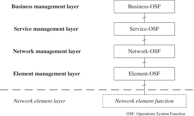
Figure 2.20 ITU‐T model for layering of TMN management functions [27].
TMN information architecture: TMN Management Services require the exchange of management information between the elements of managing and managed systems. Standardized information models consist of information elements that are abstractions of resource types, usually modelled as objects. Further, they contain an abstraction of the management and management support aspects of a network resource. Information models are mapped to reference points of the TMN functional architecture. Thus, the resulting information model of a reference point unifies the TMN functional and information architectures, defines the minimum scope of management information to be supported by the associated function blocks, and usually corresponds to the physical interface of the TMN physical architecture.
TMN physical architecture depicts the configuration of the physical equipment of a TMN. It comprises two fundamental elements: physical blocks and physical interfaces. Physical blocks are subdivided into Network Element (NE), Operation System (OS), Workstation (WS), and transformation devices that host function blocks providing conversion between different protocols or data formats. The physical architecture model mandates that each physical block at least host the accordingly named function block of the functional architecture. Nevertheless, the recommendation does not exclude additional associations between function blocks and physical blocks. The OS physical block can typically be further broken down into the four logical layers, i.e. Business (B‐OS), Service (S‐OS), Network (N‐OS), and Element E‐OS, each containing the associated function block.
The general scoping of telecommunications management by ITU‐T has been utilized by industry organizations to define norms, standards, industry specifications, frameworks, and best practices on different management layers. For example, the TM Forum has defined the so‐called Frameworx concept, consisting of
- (1) the Business Process Framework or enhanced Telecom Operations Map (eTOM) [51], which defines service operations procedures, such as, fulfilment, assurance, billing/revenue management, or operations support functions
- (2) the Information Framework [52], describing data definitions and according information models required for service operations
- (3) the TM Forum Application Framework (TAM) [53], describing a service provider's ecosystem of OSS/BSS applications.
As a whole, Frameworx covers the service and (parts of) the business management layers as defined in TMN. The next subsection focuses on the network and element Management layers and how they have been further standardized or specified in selected network domains.
2.6.2 Network Management Architectures
For the network and element management layers, different TMN management areas have defined their dedicated realization of the generalized TMN functional architecture. For example, 3GPP working group SA5 has specified the management reference model and interfaces for mobile networks as depicted in Figure 2.21 [54].
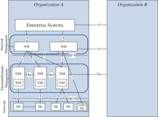
Figure 2.21 3GPP management reference model.
Source: Adapted from [54].
Functions of the network and element management (NM/EM) layers are summarized as the Operations System, which interfaces with the network element layer and other enterprise (service management) systems in southbound and northbound direction, respectively, and with peer‐level functions in other organizations in the horizontal direction. Exemplary functions of the NM layer include management and orchestration of network services, network planning (including radio planning), network configuration management, alarm and event correlation, network supervision, and centralized SON automation. On the EM/DM layer (3GPP adds domain management to this layer), typical functions include element‐ and domain‐level configuration management, network performance monitoring, alarm correlation, and distributed SON automation.
Further, seven types of management interfaces have been defined in the 3GPP management reference model. The most important ones include Type 1 management interface (also referred to as Itf‐S) between an NE and an Element/Domain Manager of a single PLMN organization and Type 2 management interface (also referred to as Itf‐N) between the Element/Domain Manager and the Network Manager of a single organization. In rare cases, Network Managers can also have a direct interface with the NE. Horizontal management interfaces (Type 5/5a) between two different organizations usually only exist on a peer level and are typically restricted to higher (network and above) management layers, cf. Figure 2.21. For 5G networks, these horizontal interfaces across administrative domains will become of higher relevance, because of private mobile networks and increasing levels of network sharing, e.g. through network slicing, a 5G concept for deploying multiple logical networks with own management functions on a shared infrastructure. Both will require a tighter interaction between the network management functions of the involved networks and organizations. More details on these topics are presented in Section 2.7
2.6.2.1 Legacy 3GPP Management Integration Architecture
In 3G and 4G mobile networks, 3GPP adopted a top‐down, process‐driven interface modelling approach referred to as the Integration Reference Point (IRP) concept [55]. IRPs comprise the so‐called IRP categories and IRP levels. IRP categories include
- Interface IRP: this category defines operations and notifications for a specific telecom management domain, such as, alarm management or configuration management. It describes how information is exchanged on an interface
- Network Resource Management(NRM) IRP: this category defines the managed objects, i.e. the so‐called Information Object Class which represents the manageable aspect of the resource of this IRP.
- Data Definition IRP: this category includes the data definitions commonly used by Interface IRPs and/or NRM IRPs.
A three‐level approach is used to define each IRP category, i.e. each category is partitioned into the following specification levels:
- Requirements: this level includes the conceptual definitions of management interfaces based on selected use cases and subsequently defines concrete requirements for the IRP. The specifications of this level should be rather stable over a longer period of time
- Information Service(IS): based on the requirements level, the IS‐level provides technology‐agnostic definitions for each IRP category. The specifications of this level should only change by means of additions and extensions
- Solution Set(SS): the SS‐level provides a mapping of each IS definition to technology‐specific solutions, e.g. to a management protocol, such as, CMIP, NETCONF, CORBA, or SOAP. The specifications of this level may change if new or better technologies become available.
Using this fundamental approach, 3GPP specifies the procedures for each of the management domains of the FCAPS model and, beyond those, for the following domains: roaming management, fraud management, software management, subscription management, subscriber and equipment trace management, service level trace management, and management of the TMN itself. For further details, the reader is referred to the 3GPP specification series 28 and 32 on telecommunications management [56,57].
2.6.2.2 Service‐Based Architecture in Network Management
Similar to the 5GC control plane, 3GPP has defined the Service‐Based Management Architecture (SBMA) for the management plane [58]. A management service offers management capabilities and can combine three so‐called management service component types which correspond to the IRP categories defined in Section 2.6.2:
- Type A is a group of management operations and notifications independent of managed entities. This type corresponds to the ‘Interface IRP’ category. Examples include single or bulk configuration management interfaces or interfaces for synchronous and asynchronous performance management data exposure.
- Type B comprises the management information represented by information models of the managed entities (managed object). This type corresponds to the ‘NRM IRP’ category. Examples include NRMs defined for the different NFs of the 5GS, such as, AMF, SMF, PCF, or the gNB.
- Type C comprises performance and fault information of the managed entities (‘managed data’). This type corresponds to the ‘Data Definition IRP’ category. Examples include counters for ping‐pong or too‐late/too‐early handovers, radio link failures, and dropped calls.
A management service combines components of either Types A and B (i.e. what are the operations/notifications associated with a specific managed object) or Types A, B, and C (i.e. what are the operations/notifications associated with a specific managed object and which managed data is processed). Service capabilities include, but are not limited to, Configuration (also referred to as Provisioning), Performance, and Fault Management (CM, PM, FM, respectively) capabilities. In the case of a CM service, the service producer is the entity being configured, i.e. it receives CM parameters from the service consumer. Management services can be offered on any management layer, cf. the ITU‐T model for layering of TMN management functions in Figure 2.20. Typically, service consumption happens in a ‘bottom‐up’ manner, i.e. services produced on lower layers, e.g. element management, are consumed by consumers on a higher layer, e.g. domain management. Another example comprises the consumption of a Network Function Management Service (NFMS), e.g. a PM service, by an entity on the network slice subnet management level which, in turn, can offer a PM‐related Network Slice Subnet Management Service (NSSMS) to an entity on the network slice management level. For further details on 3GPP SBMA, see [58].
2.6.3 The Role of Information Models in Network Management
It requires a huge number of management applications on the different layers of the network management architecture (cf. Figure 2.21) to manage all aspects of the overall network, which comprises the RAN with several thousand network elements deployed across the country (including the necessary site equipment such as tower mount amplifiers, active antennas, and routers), as well as the many hundreds of network elements of the core and transport networks. The communication between all these entities is based on a huge variety of interfaces, by which the systems expose their internal behaviour in an abstract way to their communication partners. Each of these interfaces uses protocol stacks with multiple layers, which require models on all levels of abstraction that can be described by different meta data possibly in many different languages. As a consequence, over the years, the industry implemented a Babylonian language problem.
Information models in the management of telecommunication networks have become extraordinary heterogeneous over the last decades for a variety of reasons. On the one hand, the different network elements differ in scaling and deployment which results in different management applications and requirements for the corresponding interfaces. On the other hand, changing existing interfaces imposes costs and risks for both vendors and MNOs, such that the inertia of changing existing, working interfaces for the sake of harmonization must not be underestimated.
Generally, the description of different aspects of each interface causes many misunderstandings in discussions owing to differences in backgrounds and assumed context for the different stakeholders. Moreover, the multiple interfaces with different levels of abstraction and layers imply a huge complexity and cost in real‐life systems, since all these interfaces along with all their aspects must be documented, implemented, and maintained in the long term. Each newly arriving generation of RAT increases the number interdependencies and deployment options such that the number of interfaces and the related effort to maintain them also increases. Given these challenges, it appears obvious to require common management interfaces and common information models to reduce the complexity and allow for generic or vendor‐independent solutions.
So far, although the industry has developed and standardized common interfaces for specific layers and types of network elements, (see for example [56,57]), it was not able to agree on an overall, common ‘lingua franca’ that harmonizes all the interfaces. Specifically, the idea of starting from the very different entities to derive a common model has not been successful. Instead, an alternative candidate approach is to derive common models – even of different managed elements – based on the requirement that it should be possible to handle common use cases in a common way. For example, the different managed entities all require means to manage the inventory, software versioning and faults. Common defined models based on this requirement would become enablers to handle common aspects of the systems by common applications. However, this approach immediately reveals the inherent limitations of common models: If there is no common use case for a certain aspect of two managed entities, then there is no chance to cover these aspects by a common information model. So, multiple information models have been developed for use in different contexts as discussed in the subsequent sections.
2.6.4 Dimensions of Describing Interfaces
Network management involves several management functions with different focus, scope, and levels of abstraction. Each corresponding interface can be described on different levels of abstraction, and each interface is based on a stack of protocols. Each perspective of describing interfaces may be considered as a distinct dimension of network modelling, which also has distinct requirements. The following paragraphs briefly describe the dimensions, based on which models may be developed to manage communication networks.
2.6.4.1 Dimension 1: Hierarchy of the Management Function
As shown in Section 2.6.1 the different tasks related to operating and managing a telecommunication network can be grouped into a hierarchy of management functions comprising of Business Management, Service Management, Network Management, Element Management, and the Network Elements/Network Functions. Each layer has a specific scope in terms of managed network elements, a specific level of abstraction of those elements and a specific time scale of its operations. Consequently, the overall management system forms a ‘Telecommunication Management Network’ [50] with multiple different interfaces to support a broad variety of use cases, which leads to multiple models.
In many operators' networks, these graphs of management functions and their interfaces have been specifically designed to support the organizational structure and workflows of individual operators. These environments, which have gradually grown over decades, comprise several dozens of network management applications that are partly customized products from different vendors while the rest have been individually, or even internally, developed applications. Together, they represent a considerable investment and are business critical for the operator, as any changes to the functions or their interfaces imposes costs and risks, which the operator would rather avoid. This is, in many cases, the reason not to adopt standardized interfaces when they would be available. ITU‐T recognizes that ‘functional and information architecture provide a framework that allows requirements to be documented about what a TMN implementation should do’ and that ‘TMN implementations are not currently a subject for standardization’, because ‘TMN implementations have to blend and balance a number of divergent constraints such as cost, performance, and legacy deployments, as well as new functionality being delivered’ [50].
However, with each new generation of technology, the number and complexity of tools for management, optimization, and automation has considerably increased, which has led to a significant burden to develop and maintain the corresponding interfaces. This is the one motivation for. 3GPP [56,57] and ZSM, for example, to drive harmonized reference architectures with standardized interfaces between the management functions.
2.6.4.2 Dimension 2: Levels of Abstraction
Any function and each interface between them can be described by several levels of abstraction. A product manager's view on the business requirements is more abstract than a systems engineer's view, which is also different from that of a developer who must deal with the very details of the code. Accordingly, many standardization bodies adopted these levels of abstractions, such as the concept of 3GPP to separate ‘Requirements’, implementation agnostic ‘Information Service’, and multiple implementation specific ‘Solution Sets’ [55].
2.6.4.3 Dimension 3: Layers in Communication
Interfaces between software systems are based on protocol stacks (e.g. ISO/OSI) and are often based on sets of protocols (e.g. CORBA might be used to control the exchange of files, while the actual transfer of files is performed by ftp). Successful communication requires the sender and receiver to use the same sets of protocols and protocol stacks. Peers need to use an agreed dynamic behaviour to exchange data, a well‐defined format to structure information elements, and a common understanding on the semantics of the different information elements. All these aspects are equally as important for each layer.
2.6.4.4 Dimension 4: Meta Data
Meta data is used to describe data. Each of the above‐mentioned aspects of the interfaces (hierarchy, abstraction or layer) can be described by meta data, while different target groups use different languages to describe the interfaces. While product managers might use plain text, system engineers may prefer the Universal Modelling Language [59], an implementation‐independent language used to model various static and dynamic aspects of systems, such as software systems or telecommunication systems. Similarly, software designers may use implementation‐specific interface definition languages (IDL) to generate artefacts to ease the implementation of the software in a specific technology.
2.6.5 Network Information Models
Considering the many dimensions, it is obvious that many different kinds of models may be developed to integrate the management functions and managed entities in a communication network. This section analyses how far common protocol stacks and common meta data might enable further automation and will emphasize some inherent limitations of common management interfaces.
2.6.5.1 Model of the Dynamic Behaviour
To integrate a managed entity into a management system, communication between them depends on a common dynamic behaviour, i.e. a common notion on how to organize the exchange of data. The model of the dynamic behaviour of an interface describes how the entities exchange the data, independently of the format or the semantics of the data.
As an example, the dynamic behaviour of internet protocol v4 (IPv4) is passive, i.e. the IPv4 sender puts up to 65 535 logical 1 or 0 on the wire but does not care about any receiver. Multiple receivers might read the data from the wire, and if a receiving interface detects that it is the destination of the data, it will handle the data, while other interfaces shall ignore the data. In contrast, the dynamic behaviour of TCP/IP comprises additional handshaking mechanisms to ensure the correct transmission of the data and to address processes within a server. Protocols on top of TCP/IP utilize the mechanisms provided by TCP/IP, which they augment by additional message sequences to perform specific tasks resulting in different dynamic models. For example, both, ftp and http are meant for file transfer, but they are based on fundamentally different dynamic behaviour: ftp establishes a logical connection (session), transfers one or multiple files in either direction, and then closes the connection. In contrast, http is connection‐less, in the sense that the client sends a request for a file to the server and, in turn, receives the requested file as the answer –without the need for the client to open and close an explicit session.
In general, an interface has to mediate between three dynamic behaviours: the internal behaviour of the managed entity, the dynamic behaviour of the interface itself, and the internal behaviour of the managing entity. These dynamics might be very different. For example, the configuration of the managed entity may require the complete configuration database to be exchanged, while the management entity and the interface are designed to deliver individual commands to modify single parameters. There are mismatched expectations if the management system's Performance Management (PM) database is optimized to write many records of the same measurement type while the interface is optimized to transfer big files. The two would match if a file sent by a managed entity contains blocks of measurements of same type. This is, however, rarely the case. There is considerable overhead in communication on the interface if the managed entity sends small files containing only one record. Most importantly, the database has to handle each record by an individual transaction and so the managed entity may have to sequentially cycle through hundreds of different measurement types.
Besides mismatches, the internal behaviour of network elements might be restricted due to the requirements of their functionality in the network, which then demands for different approaches in dealing with these network functions. For example, a BTS cannot change certain parameter values without dropping ongoing calls. As a consequence, a managing entity cannot assume an instant change for such parameters if continuity of the service for the end customer is required.
For different network elements to be connected by a common interface with common dynamic behaviour, the dynamic behaviour of the network element must be compatible to the interface. Otherwise, the network elements have to implement a mediation component to map the internal dynamics to the dynamics of the interface. While this is doable, it is very expensive in terms of R&D, risk, and runtime resources.
The interfaces enable the management systems to perform a transformation in scale and capacity. One management system might use its interfaces to integrate hundreds of thousands of managed entities, each providing small amounts of data. However, from a management system point of view these many small amounts add up to a huge amount. Besides the amount of data, the management system must also handle the load caused by the dynamic behaviour of hundreds of thousands of interfaces towards the managed entities, e.g. to open, maintain, and close long‐lived sessions and, especially, to handle exceptional conditions if connections die unexpectedly. Depending on the managed entities, requirements for scaling might be very different. Harmonization of interfaces should consider such differences in scaling.
As shown, there is definitely no ‘one interface fits all’ scenarios. Managed entities with similar dynamic behaviour and similar requirements from a management system point of view regarding scale and capacity should use the same model of the dynamic behaviour (protocol) to transfer the data. However, a management system that needs to integrate different categories of managed entities must be prepared to support multiple protocols. In other words, it may sometimes be necessary to introduce new protocols/interfaces to the management entity. Since the dynamic behaviour of managed entities is usually very stable across releases of the managed entity, the integration of a new protocol into a management system is typically a one‐time exercise. This addition of interfaces is, however, an expensive and high‐risk exercise that is also prone to new errors and problems. As such, new interfaces should be introduced with caution as a fundamental mismatch between the dynamic behaviours of the interface and the managed entity increases the chance of failure. Simply stated, a sub‐optimal interface that is working is better than an interface that would be perfect in theory but failing in reality due to implementation issues.
2.6.5.2 Format of the Data
Besides the dynamic behaviour, integration of a managed entity into a management system also depends on the commonality of the formatting of the data, i.e. a common notion of the structure of the data and its partitioning into information elements. The model of the format describes how the data, irrespective of the mechanisms to transfer the data or its semantics, is partitioned into information elements. For example, IPv4 defines packets with up to 65 535 binary bits, has a mandatory header section of 5 × 32 bit containing 13 header fields, and an optional header of up to 4 × 32 bits, but does not impose any format or structure to the data in the payload.
An interface must transform between three different formats: The internal format of the managed entity, the inherent format of the interface, and the internal format of the managing entity. Usually, the data transfer is organized in stacks of protocols. For a given managed entity, the lower layers of the protocol stack usually do not change with new releases of the managed entity. This is also true for the format of the data of such lower layers, e.g. the coding of the management data into file formats like XML, json, csv, asn.1, xdr, or protobuf is usually very stable. Also, the notion of alarms that are modelled by well‐defined fields or the concept to organize configuration data as objects which contain parameters with values is usually stable across releases of network elements. Mapping these formats into a common model is a one‐time task, which is not usually complex and thus technically feasible.
In contrast, the specific set of information elements exposed by a managed entity on its management interfaces does depend on the release of the managed entity, therefore, the corresponding management systems must be enabled to handle the additional information elements. This preparation might be complex, since the management system might need to adapt its internal storage system and data access functions, its internal communication systems, and its user interface. In addition, the management system must cope with multiple versions of managed entities in parallel due to the fact that a network‐wide upgrade might take several weeks where parts of the network have already been upgraded while other parts are still running the old release.
If an upgrade of a managed entity requires manual work to adapt (i.e. code) and to release a new version of the management systems, which might also potentially require involvement of third‐party‐suppliers, then the upgrade will be both expensive and slow. Typically, operators require lead times of three to six months to adapt network management tools to new network elements releases, which is incompatible with the flexibility required by 5G. In contrast, a management system that uses generic, metadata‐driven tools for data parsing and processing is able to read the description of the updated format and to automatically adapt its internal structures (including database tables, internal communication, and user interface). Although the development of a metadata‐driven tool is much more complicated than a statically coded tool, the automated adaptation enables much faster introduction of new features, which might be more important than the costs of the initial implementation.
The upgrade process can further be automated using an interface that enables the managed entity and the management tool to exchange the metadata. Such an interface may use any of the known metadata transfer languages e.g. XMI for UML, CorbaIDL for Corba, XML Schema, WSDL, or YANG. However, since such additional metadata interfaces all have concerns and dimensions as for any other interface, dependencies and long‐term maintenance effort might increase considerably.
2.6.5.3 Semantical Part of the Model
Besides the dynamic behaviour and data format models, an interface requires the sender and receiver to agree on common semantics of the information elements. In IPv4, for example, the octets 12–15 indicate the source IP address and octets 16–19 the destination IP address while IP does not prescribe any semantics for the payload, i.e. the serviced data unit. The common understanding of the data semantics allows the communicating entities to accurately interpret the data. Similarly, for management systems, proper handling of the operability data requires the management system and the managed entity to have a common understanding of the meaning of the individual information elements. In this respect, the operability data represents the behaviour of the managed entity, so proper interpretation on both sides is needed to accordingly and appropriately define the behaviour.
2.6.6 Limitations of Common Information Models
As discussed, the degree to which the network can be uniformly controlled, depends on the common understanding of the information elements. Today's networks are characterized by both standard and proprietary features and information elements.
The well‐known standardization bodies (3GPP, IETF, ITU‐T, etc.) define the call processing procedures between the network functions, e.g. the messages that must be exchanged between the network elements to provide the telecommunication service, e.g. to establish a connection between a user equipment (UE) and the RAN or to perform a proper handover. This guarantees interoperability of network functions and devices from different vendors. Each network function that fulfils a given standard must represent the corresponding properties and parameters with the standardized semantics (e.g. frequency of a cell, cell‐Id, system information on broadcast channels, etc.). These have been the causes for the huge success of standardization in telecommunication and the big differentiator compared, say, to the highly non‐interoperable solutions of the internet applications.
From the management point of view, the operator can implement common use cases for all these standardized parameters of the corresponding network elements regardless of the vendors, e.g. the planning and assignment of frequencies, cell‐Id, and broadcasted system information can be performed for any vendor's cell in the network. In these cases, it is possible to map the standardized parameters into a common information model with agreed semantics of the individual information elements that can be handled by common applications.
By intention, 3GPP does not define the internal algorithms of the network function. For example, each vendor has the freedom to define how and when a BTS decides to perform a handover, to which target cell, and how to consider traffic steering and load balancing. This freedom leaves room for differentiation and technical evolution and will persist as long as vendors are required to differentiate by features.
The air interface of the RAN especially requires very complex algorithms that apply many rules and policies to optimize utilization of the spectrum and to ensure the best possible quality to users. A real‐world cell in UTRAN or E‐UTRAN requires approx. 1000 parameters, while approx. 10% of these parameters are standardized and 90% relate to proprietary algorithms.
However, from the management point of view, this freedom has dramatic consequences, because these proprietary, internal algorithms do not have any analogy on implementations of other vendors. There is no common use case to set or to optimize the corresponding vendor/feature‐specific parameters. The semantics of these vendor/feature‐specific parameters cannot be mapped to a common information model. These vendor/feature‐specific parameters cannot be handled by common applications that depend on the semantics.
The situation gets even more complex due to the many dependencies within a network function between standardized parameters and vendor‐specific parameters. For example, in most cases, it is not possible to configure a real‐life cell without touching the vendor‐specific parameters, which then implies that generic configuration tools are not possible for even the most basic configuration use cases.
As long as the external behaviour of network elements will be standardized while, at the same time, technical evolution and differentiation of network elements is required, the information models will comprise information elements with both standardized and vendor‐specific semantics. As a consequence, management systems must be able to cope with such heterogeneity.
It follows that common information models are not possible, at least in foreseeable future. However, other common models could be developed. This, however, requires a detailed re‐evaluation of the approach to network modelling to identify the areas where such models could be possible. The next section presents such an approach and studies the challenges from a systems theory perspective.
2.7 Conclusion – Cognitive Autonomy in 5G and Beyond
MNOs and CSPs have always looked to network automation to improve operational and cost efficiency. Past efforts focused on small steps delivering incremental benefits. SON, automated LCM and APIs allow for programmatic change of network parameters have been proof points for such incremental automation attempts that have, so far, not materialized the vision of cognitive autonomous networks. Dependencies in the management of physical radio networks and of virtualized infrastructure components are major obstacles. Further drivers of MNOs' need for cognitive autonomy in 5G mobile networks include explosion of parameter space, user‐and service‐specific customization of networks and network elements, variations of network deployment flavours, functional decomposition, and management of multitudes of logical network instances. Overall, four major challenges for 5G mobile network management automation can be identified:
- 1. Management of novel 5G network features which entails management of feature flexibility requiring dynamic configurability and management of feature complexity with the related vast configuration space and dependencies
- 2. End‐to‐end operation of 5G networks
- 3. Vertical sectors as novel operational stakeholders in 5G system operation.
2.7.1 Management of Individual 5G Network Features
5G mobile network design introduces an extensive infrastructure heterogeneity and flexibility for implementing the network domains (RAN, CN, etc.). In the RAN, this manifests through novel architecture, allowing for a large variety of network function deployments, and a number of flexible and configurable radio features, e.g. the application of a broad range of frequencies, multiple RAT numerologies [60] or flexible beamforming. In the core, formerly monolithic network elements are decomposed into more fine‐grained and frequently virtualized NFs that can be executed in different locations, cf. Section 2.4.6. Moreover, the architecture must integrate various cell types and sizes from classical macro‐cells down to pico cells for ultra‐dense network deployments, the use of different radio technologies, diverse transport topologies (fronthaul/backhaul), and the (joint) use of licensed and unlicensed spectrum. The introduced flexibility and means for dynamic re‐configurations of network features requires new capabilities of the management and orchestration systems.
2.7.2 End‐to‐End Operation of 5G Networks
On the end‐to‐end system level, the major challenge arises from the identification and enforcement of an appropriate network operating point, i.e. a comprehensive and reconciled configuration of all network features. Generally, network operations entail the adjustment of the operating point in case of, for example, changes in service requirements, traffic and user distribution or the network context and, finally, its optimization according to the required performance and operational targets. In 2G/3G/4G network deployments, it is possible to determine an appropriate operating point with manageable effort, as the influencing variables are well‐known, and their number is limited. In order to keep or adapt the – rather stationary – operating point in an automated way, the industry has developed quasi‐static closed‐loop control systems called SON functions (cf. Chapter 3). These SON functions have been applied for the configuration, optimization, and failure recovery [61]. In contrast, 5G networks will have considerably more influencing variables resulting from the highly configurable network implementation, i.e. the technological advances in radio technology, overall system heterogeneity and deployment modularity, as well as the mixed physical and virtualized environment. Different communication services will require different operating points owing to the different performance targets, which are likely to change more frequently than today. 5G management systems should address such different and dynamic performance targets by identifying and virtually configuring different operating points simultaneously. The existing SON approaches will probably not provide a sufficient degree of flexibility and dynamicity for implementing an appropriate cognitive 5G network management.
2.7.3 Novel Operational Stakeholders in 5G System Operations
The final challenge is brought in by the requirement of serving multiple vertical industries via virtual network instances, so‐called ‘network slices’, each of which may serve a dedicated ‘vertical’ company, a so‐called tenant. Each instance can be considered as a self‐contained network from a tenant's point of view. For each instance, the CSP not only has to identify an operating point and derive according network configurations, but may also have agreed on a contract‐specific level of network management features delegated to the tenant. This exposure of former operator‐internal functionality can range from a rather simple monitoring of the slice's Quality of Service (QoS) or Quality of Experience (QoE) performance, according to targets agreed in an SLA, to a rather deep control in terms of re‐configuring a (virtualized) network function within certain boundaries. Besides exposing selected management features in such a way as to preserve overall security and operational safety of the network, the challenge for the CSP comprises the resolution of conflicting configurations made by different tenants but affecting the same network segment or network function.
In summary, there is a strong requirement for cognitive methods and tools that allow the network to autonomously exploit the emerging flexibility and opportunities provided with the new 5G features. The objective for the network management system is to largely autonomously configure network resources and functions in such a way that each network slice instance reaches its optimal operating point to meet the performance and operability requirements. Cognitive autonomous management needs to map these multiple operating points to the available infrastructure resources in an SLA‐conforming and non‐conflicting manner.
References
- 1 3GPP TS 23.002 (2018).Network architecture. Sophia Antipolis: 3GPP.
- 2 3GPP TS 23.401 (2018). General Packet Radio Service (GPRS) enhancements for Evolved Universal Terrestrial Radio Access Network (E‐UTRAN) access. Sophia Antipolis: 3GPP.
- 3 3GPP TS 23.107 (2018) Quality of Service (QoS) concept and architecture. Sophia Antipolis: 3GPP.
- 4 3GPP TS 25.308 (2017). High Speed Downlink Packet Access (HSDPA). Sophia Antipolis: 3GPP.
- 5 Eberspächer, J., Bettstetter, C., Vögel, H.‐J., and Hartmann, C. (2008). GSM ‐ Architecture, Protocols and Services, 3e. Wiley.
- 6 Holma, H. and Toskala, A. (eds.) (2010). WCDMA for UMTS: HSPA Evolution and LTE, 5e. Wiley.
- 7 3GPP TS 23.203 (2019). Policy and charging control architecture. Sophia Antipolis: 3GPP.
- 8 Holma, H. and Toskala, A. (eds.) (2011). LTE for UMTS: Evolution to LTE‐Advanced, 2e. Wiley.
- 9 3GPP TS 23.402 (2018). Architecture enhancements for non‐3GPP accesses. Sophia Antipolis: 3GPP.
- 10 IBM (2016). A Practical Approach to Cloud IaaS with IBM SoftLayer. IBM Redbooks.
- 11 Nokia Networks (2015). Reinventing telcos for the cloud. https://resources.nokia.com/asset/200238 (accessed 20 January 2020).
- 12 Brown, G. (2017). Designing Cloud‐Native 5G Core Networks. https://www.juniper.net/assets/us/en/local/pdf/whitepapers/2000667-en.pdf (accessed 20 January 2020).
- 13 Taylor, M. (2016). Telco‐Grade Services From An IT‐Grade Cloud. https://www.metaswitch.com/knowledge-center/white-papers/telco-grade-services-from-an-it-grade-cloud. (accessed 31 January 2019).
- 14 3GPP TR 22.804 (2018). Study on Communication for Automation in Vertical domains (CAV). Sophia Antipolis: 3GPP.
- 15 3GPP TR 22.821 (2018). Feasibility Study on LAN Support in 5G. Sophia Antipolis: 3GPP.
- 16 ETSI GS NFV‐MAN 001 (2014). Network Functions Virtualisation (NFV); Management and Orchestration. Sophia Antipolis: ETSI.
- 17 Nokia Networks (2019). Creating new data freedom with the Shared Data Layer. https://resources.nokia.com/asset/200238 (accessed 24 January 2020).
- 18 Nokia Networks (2017). Mobile anyhaul. https://resources.nokia.com/asset/201272 (accessed 24 January 2020).
- 19 3GPP TS 23.501 (2018). System Architecture for the 5G System. Sophia Antipolis: 3GPP.
- 20 3GPP TS 23.502 (2019). Procedures for the 5G System. Sophia Antipolis: 3GPP.
- 21 3GPP TS 23.503 (2018). Policy and charging control framework for the 5G System. Sophia Antipolis: 3GPP.
- 22 The Open Group (2019). Service Oriented Architecture (SOA). https://collaboration.opengroup.org/projects/soa/pages.php?action=show&ggid=1575. (accessed 18 June 2019).
- 23 3GPP TS 29.518 (2018). Access and Mobility Management Services. Sophia Antipolis: 3GPP.
- 24 3GPP TS 29.501 (2018). Principles and Guidelines for Services Definition. Sophia Antipolis: 3GPP.
- 25 Fielding, R.T. (2000). Architectural Styles and the Design of Network‐based Software Architectures. Doctoral Dissertation. University of California.
- 26 Maeder, A., Ali, A., Bedekar, A. et al. (2016). A scalable and flexible radio access network architecture for fifth generation mobile networks. IEEE Communications Magazine 54 (11): 16–23.
- 27 3GPP TS 38.300 (2019). NR and NG‐RAN Overall Description. Sophia Antipolis: 3GPP.
- 28 3GPP TS 38.401 (2019). NG‐RAN; Architecture description. Sophia Antipolis: 3GPP.
- 29 3GPP TS 38.470 (2019). NG‐RAN; F1 general aspects and principles. Sophia Antipolis: 3GPP.
- 30 3GPP TS 38.460 (2019). NG‐RAN; E1 general aspects and principles. Sophia Antipolis: 3GPP.
- 31 Ericsson A.B. (2018). Common Public Radio Interface: eCPRI Interface Specification. Huawei Technologies Co. Ltd, NEC Corporation, Nokia.
- 32 3GPP TS 38.473 (2019). NG‐RAN; F1 Application Protocol (F1AP). Sophia Antipolis: 3GPP.
- 33 3GPP TS 38.463 (2019). NG‐RAN; E1 Application Protocol (E1AP). Sophia Antipolis: 3GPP.
- 34 3GPP TS 38.423 (2019). NG‐RAN; Xn Application Protocol (XnAP). Sophia Antipolis: 3GPP.
- 35 ETSI MEC ISG (2019). ETSI MEC: An Introduction. https://www.etsi.org/images/files/technologies/ETSI-MEC-Public-Overview.pdf (accessed 24 January 2020).
- 36 Linux Foundation (2019). LF Edge, Akraino Edge Stack. https://www.lfedge.org/projects/akraino (accessed 24 January 2020).
- 37 3GPP TR 38.801 (2017). Study on new radio access technology; Radio access architecture and interfaces. Sophia Antipolis: 3GPP.
- 38 O‐RAN‐WG1.OAM (2019). O‐RAN Operations and Maintenance Architecture. O‐Ran Alliance.
- 39 3GPP TR 23.711 (2016). Enhancements of Dedicated Core Networks selection mechanism. Sophia Antipolis: 3GPP.
- 40 RFC 3031 (2001). Multiprotocol Label Switching Architecture. IETF.
- 41 RFC 3032 (2001). MPLS Label Stack Encoding. IETF.
- 42 RFC 3985 (2005). Pseudo Wire Emulation Edge‐to‐Edge (PWE3) Architecture. IETF.
- 43 IETF, RFC 5038, “The Label Distribution Protocol (LDP) Implementation Survey Results”, Oct. 2007.
- 44 RFC 3107 (2001). Carrying Label Information in BGP‐4. IETF.
- 45 RFC 5921 (2010). A Framework for MPLS in Transport Networks. IETF.
- 46 CCITT (1992). Recommendation M.20. Maintenance philosophy for telecommunication networks. ITU.
- 47 CCITT (2000). Recommendation M.3000. Overview of TMN Recommendations. ITU.
- 48 CCITT (1997). Recommendation M.3200. TMN management services and telecommunications managed areas: overview. ITU.
- 49 CCITT (2000). Recommendation M.3400. TMN management functions.ITU.
- 50 CCITT (2000). Recommendation M.3010. Principles for a telecommunications management network. ITU.
- 51 TM Forum (2018). GB921. Business Process Framework (eTOM) Suite. Release 18.5.
- 52 TM Forum (2019). GB922. Information Framework (SID). Release 18.5.
- 53 TM Forum (2018). GB929. Application Framework (TAM) Suite. Release 18.5.
- 54 3GPP TS 32.101 (2017). Telecommunication management; Principles and high level requirements. Sophia Antipolis: 3GPP.
- 55 3GPP TS 32.150 (2018). Integration Reference Point (IRP) concept and definitions. Sophia Antipolis: 3GPP.
- 56 3GPP. Specification Series 28, Telecom Management. http://www.3gpp.org/DynaReport/28-series.htm (accessed 24 January 2020).
- 57 3GPP. Specification Series 32 Telecom Management. http://www.3gpp.org/DynaReport/32-series.htm (accessed 24 January 2020).
- 58 3GPP TS 28.533 (2019). Management and orchestration; Architecture framework. Sophia Antipolis: 3GPP.
- 59 OMG (2015). Unified Modeling Language TM (OMG UML). Object Management Group.
- 60 Pedersen, K., Berardinelli, G., Frederiksen, F. et al. (2016). A flexible 5G frame structure design for frequency‐division duplex cases. IEEE Communications Magazine 54 (3): 53–59.
- 61 Hämäläinen, S., Sanneck, H., and Sartori, C. (eds.) (2011). LTE Self‐Organising Networks (SON): Network Management Automation for Operational Efficiency. Wiley.