Chapter 11. Troubleshooting Cisco Device Mobility Issues
With mobile workforces, things have become more dynamic. Users no longer exclusively take calls from the desk phone dedicated to them in their office. Now they want a greater degree of mobility while maintaining their corporate identity—wherever they are in the enterprise. Device Mobility enables phones to roam between physical locations while still being recognized by the Cisco Unified Communications Manager (CUCM) and have calls properly routed both to and from the device in question. This chapter deals with how to address common issues arising with this feature.
Chapter Objectives
Upon completing this chapter, you will be able to
• Describe the key concepts of Device Mobility
• Describe the call-routing implementation options of Device Mobility
• Describe common Device Mobility–related issues and their causes
• Troubleshoot Device Mobility configuration mismatches
• Troubleshoot Device Mobility call-routing issues
• Troubleshoot issues that are related to calling privileges
Device Mobility Overview
A single (physical) site or location is identified using a meaningful naming convention. The more meaningful and descriptive the names used within the CUCM configuration, the easier it is to troubleshoot. Typically, a physical location is allocated specific configuration parameters within the device pool that include the following:
• Region
• Calling search spaces (CSS)
• Local route groups
• Emergency location identification numbers
• Media resources
These settings are usually static in nature. They don’t change because the phones don’t move from site to site.
That is not always the case, however. In numerous use cases, dual-mode phones (Jabber for iOS/Android) roam between sites. This is also the case for wireless 7921, 7925, and 7926 model IP phones. Sometimes, employees move between sites and take their desk phones with them.
Unless configured properly, all these devices will maintain their static settings for location, device pool, and so on. The Device Mobility feature enables CUCM to determine if the phone is in its home location or some remote location. Using this feature, mobile users can bounce between sites at will and be confident that their calls route properly (for example, 911 calls) while using the proper media resources for that site.
Figure 11-1 shows a general topology including a central site with two remote sites.
Figure 11-1. Central Site with Two Remote Sites

In Figure 11-1, assume that intrasite calls use G.711 and intersite calls use G.729a across the WAN connections. Each site, as shown, has its own public switched telephone network (PSTN) connection. Under normal operation, a Dallas phone utilizes the Dallas PSTN connection, a San Jose phone utilizes the San Jose PSTN connection, and an Atlanta phone utilizes the Atlanta PSTN connection.
If Device Mobility has not been configured, CUCM is not aware that the phone has changed sites. So, in cases in which a user roams between sites—for example, a Dallas user is in San Jose—a call placed to a PSTN destination would traverse the WAN connection and egress via the Dallas voice gateway. Additionally, with the codec configuration specifying that G.729a be used for intersite calls, more bandwidth than intended will be used by every call. The reason is that CUCM knows only that the user’s phone is based in Dallas, so it’s an intrasite call and will use G.711.
Two key issues arise here. First, PSTN calls placed by the Dallas user egress via the Dallas gateway. This seemingly minor misconfiguration is limited in impact until that user places a 911 call. At that point, the issue becomes serious. If an emergency situation requires 911 assistance in San Jose, the Dallas public safety answering point (PSAP), the call center responsible for handling emergency calls, is not able to effectively offer the necessary help. Second, the bandwidth utilization of voice calls between sites is not preserved in optimal state. This is not only in terms of codec bandwidth utilization; it also brings in concerns surrounding media resources, which are likely across the WAN as well. If the visiting Dallas user calls a San Jose phone, depending on the configuration, either the call will set up between them using G.729a, or the call could be hitting a transcoder in Dallas to convert G.711 to G.729a. The more likely scenario would be a conference call. If the roaming user creates an ad hoc conference with two San Jose users, the Dallas user’s media resource configuration dictates the conference bridge resource to be utilized. In this case, that resource is in Dallas. So, all the media streams will flow across the WAN, even though all three phones are in San Jose at the time the call is placed. Either way, the result is suboptimal.
One other potentially significant aspect to this situation is that CUCM doesn’t count this call against the call admission control (CAC) tracking. So, it could result in oversubscription and degraded voice quality for calls traversing the WAN, if those links are relatively low-speed links.
Much of the configuration for device-specific parameters is performed in the device pool. Device pools can be broken up in any number of ways. It is not uncommon to see a device pool per department, per device type (for example, one for phones, one for gateways), per device function (based on whether it needs Survivable Remote Site Telephony [SRST]), per site, or any number of other possibilities. The information inherited by the device pool includes a section specifically called “Roaming Sensitive Settings” and another called “Device Mobility Related Information.”
You should take care in dealing with overlapping parameters within the Roaming Sensitive Settings and Device Mobility Related Information sections of the device pool configuration, any parameter that is configurable in the device pool, and at the individual device level. This is the case for the Media Resource Group List, Location, AAR Group, and Network Locale. Figure 11-2 shows these sections of a typical device pool.
Figure 11-2. Device Pool Mobility Settings

In Figure 11-2, some key aspects of the configuration impact the user experience, ranging from cosmetic (Date/Time Group) to critical (Emergency Location Group). Additionally, the local route group (LRG) settings specify the outbound gateway for calls made to PSTN destinations. If used, the LRG allows the creation of a single route pattern pointed to the outbound gateway. It permits generic patterns, such as 911, 9.911, 9.[2-9]XX[2-9]XXXXXX, 9.1[2-9]XX[2-9]XXXXXX, 9.011!#, and others to be configured only once in the route pattern table. When each pattern is created, it can be pointed to a route list that is configured to utilize the standard local route group, which is a device pool–configured parameter, as shown in the Figure 11-2. If CUCM doesn’t know that a device has moved, it uses all the settings shown in Figure 11-2 for the roaming device. The local route group settings are included in the dynamic changes when CUCM detects a roaming phone.
Now that we’ve examined some of the ramifications, let’s discuss the configuration and architecture behind Device Mobility.
Device Mobility Architecture
Configuring Device Mobility is relatively straightforward, yet it requires some planning and consideration regarding class of service (CoS) for roaming devices. The first step in configuring it is to enable it. Open the CCMAdmin page and open the service parameters for the Cisco CallManager service. In the Clusterwide Parameters (Device – Phone) section, there is a setting for Device Mobility mode. By default, it is turned off. Set it to On, and then click Save. You immediately receive a pop-up message informing you that, for this change to take effect on devices currently registered, the Cisco CallManager service must be restarted. You will want to perform this step during nonbusiness or scheduled maintenance hours to mitigate potential service impact. Also, keep in mind that Device Mobility can be enabled or disabled at the device level. While the default setting for devices is the system default (which you just enabled), another setting may potentially disable it at the phone level.
The next step is to configure the general architectural layout of the Device Mobility design. A few elements are involved:
• Physical Location: The specific geographic location of the device pool and devices to be associated with a given device pool
• Device Mobility Group: A logical grouping of mobility-enabled devices with common dialing habits
• Device Mobility Info: Specific IP subnet information per site
First, configure a physical location for each site. You execute this step in the CCMAdmin tool by clicking System > Physical Location. Figure 11-3 shows the Physical Location Configuration page.
Figure 11-3. Physical Location Configuration Page

This part of the configuration consists solely of providing a name and description for the physical location. Create an entry for each physical site. For the example discussed up to this point, you should configure three locations: Dallas (DFW), San Jose, and Atlanta. This step is simple and straightforward. No service restarts are needed for this one.
Configure physical locations so that codec selection and CAC parameters can reflect the current location of the device. Ensure that local SRST references and media resources are available to the roaming devices rather than having them use their home site SRST reference and media resources. This way, you will avoid needless use of WAN resources in bandwidth-constrained environments. The physical locations should be specific enough to provide granularity appropriate to the network architecture.
The next configuration task is to create a Device Mobility Group (DMG). You perform this task by clicking System > Device Mobility > Device Mobility Group. Again, this is simply a name and a description with additional importance. The DMG defines a logical grouping of sites with similar dialing patterns and properties. This could be a per-country grouping, for example, because international dialing habits tend to differ, whereas dialing practices within a particular country tend be identical (Germany being a distinct exception to that particular premise). The DMGs represent the highest level of geographical entities in the network. The user roaming between Dallas and San Jose can expect to dial local and long-distance calls identically in both places. Depending on the size of your deployment, the DMGs could represent continents, countries, states, provinces, cities, or any other level of organization. They affect call routing. As such, they should be planned carefully so that roaming users are not expected to dial differently as they roam from site to site. You want the roaming to be transparent. Understand, however, that when globalized dial planning is in use (E.164 directory numbers with +1 dialing everywhere), the Device Mobility Group becomes irrelevant because there is no need to alter call-routing rules at that point.
Figure 11-4 shows the Device Mobility Group Configuration page.
Figure 11-4. Device Mobility Group Configuration Page

Finally, you must perform the key aspect of the Device Mobility configuration. This task can be labor intensive because it requires you to configure Device Mobility info for every IP subnet on which a roaming device might find itself. Obviously, phones should always be on the voice VLAN. But roaming soft phones are not always so straightforward and will likely be recognized as collaboration clients on a data VLAN. Of course, that depends on a number of factors in terms of network architecture. Regardless, all subnets need to be defined here. Figure 11-5 shows the Device Mobility Info Configuration page.
Figure 11-5. Device Mobility Info Configuration Page

As shown in Figure 11-5, the information is relatively simple. A meaningful name is provided along with the subnet and subnet mask (prefix) length in bits. In Figure 11-5, the 16-bit mask size means 255.255.0.0. Additionally, device pools need to be associated to this subnet so they can be tracked for roaming devices. Figure 11-6 illustrates the relationship between all these components.
Figure 11-6. Device Mobility Component Relationship

In Figure 11-6, the Device Mobility Group is at the top of the hierarchy, from a configuration standpoint. If this were an international company, there would likely be multiple DMGs, one for each country in which there are sites where users may potentially roam (for example, DMG-EUR or DMG-AUS for Europe and Australia, respectively). The physical location ties the device pools, which, in turn, tie in the subnets for each site.
The summarized registration process is as follows:
Step 1. An IP phone registers with its CUCM node, including its IP address in the registration message.
Step 2. CUCM notes the IP subnet of the phone and matches it to the Device Mobility Info.
Step 3. CUCM provides updated device configuration information based on the device pool configuration.
Based on the configured Device Mobility Group and Info, CUCM recognizes that the phone is either in its home site or has gone mobile. The configuration of the device is updated accordingly. Also, a message is displayed on the phone while it’s registering, noting whether it’s in its home location or a mobile location. After it confirms that it’s not in its home location, the roaming sensitive parameters and Device Mobility settings are applied, causing the phone to reset to apply the new settings.
These dynamically reconfigured parameters based on location correct the issues discussed earlier in this chapter. They allow the proper use of CAC and bandwidth allocation. They ensure that the user’s PSTN calls egress via the gateway at the local site instead of its home gateway. They also confirm that the proper codec selection is made when calling both intrasite and intersite. In fact, all the roaming-sensitive settings are updated according to the device pool associated with the subnet on which the phone is located. When the phone returns to its home location, all the settings are restored, as per the Device Mobility configuration.
Note
Take care to ensure that the phones that are using the Device Mobility feature are supported for the feature set. Phones such as the 6901 and 6911 do not support mobility. Refer to the user guide for the phones in question.
Device Mobility Call-Routing Options
Because Chapter 8, “Troubleshooting Call Routing,” went into some depth regarding dial planning and call routing, this chapter only examines partitions, calling search spaces as it pertains to Device Mobility.
Device Mobility doesn’t alter the line calling search space (LCSS) of a phone. In a typical device/line dial plan, the line level is where restrictions are applied. It does, however, change the device calling search space (DCSS) and the automated alternate routing (AAR) calling search space when the phone is roaming between locations within the same Device Mobility Group.
In a device/line approach to dial planning, the LCSS implements the CoS through the use of explicit denials for unauthorized dial patterns for the given line. It typically includes the internal calling partition(s), feature-specific partitions, along with blocks for PSTN destination route patterns as appropriate. Because this CSS is not altered, it is kept regardless of whether the phone is in its home site or a remote site.
The DCSS is replaced when a phone moves outside its home site. This CSS will refer to the local gateway for egress of PSTN calls.
With this dependency in mind, in a traditional dial plan approach with only one CSS in use, the device CSS must be utilized if Device Mobility is to function properly.
The AAR CSS is configured only at the device level. So, it isn’t taken into consideration in terms of dynamic settings being applied to the device. It is important to keep in mind the way in which AAR is configured. By the application of the DCSS, AAR group, and AAR CSS, calls can be routed differently depending on the home and remote sites of a given roaming device. This is controlled by configuring the AAR parameters using full E.164-formatted numbers. When AAR is active, egress gateway selection is handled by the configured local route group in the device pool.
A similar situation is present when international users are roaming from site to site. For example, consider a user from Germany visiting a site in the United States who needs to dial a number in Australia (+43 699 18900009). When not roaming, the user would typically dial 0004369918900009, whereas users in the United States would dial the same destination as 90114369918900009.
It is up to the collaboration architects (those who are designing the system, dial plan, supported applications, and so on) to ensure that the user does not need to change dialing behavior regardless whether he or she is roaming. To prevent the user from having to change dialing behavior, you need to suppress Device Mobility Related settings in the device pool. You do this by creating specific device pools with different dialing rules and associating them with specific Device Mobility Groups and physical locations. The roaming sensitive settings will be updated, but the Device Mobility Related pieces are not applied, leaving them as they were in their home site. Now, the user does not have to alter dialing behavior to call out. However, the correct local egress gateway will be chosen in accordance with the local route group of the site to which the user roamed.
Keep these points in mind:
• Roaming-sensitive settings are always updated when the device roams between different physical locations.
• Device Mobility Related settings are updated only if the device roams between Device Mobility Groups. Refer back to Figure 11-6.
• Within the same Device Mobility Group, the values are updated according to the roaming device pool.
• Globalized call routing fixes all of this by using E.164 numbers and +1 dialing everywhere, thereby bypassing all the confusion in how to dial various destinations depending on the current location of the device.
Common Issues
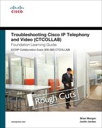
Troubleshooting Device Mobility can be easy because you can trace most common issues back to configuration errors. For reference, the Device Mobility features have been compiled into flowchart form and provided in Figure 11-7.
Figure 11-7. Device Mobility Flowchart
As is evident in Figure 11-7, the most critical aspects are the device pools, Device Mobility Group (DMG), and Device Mobility Information (DMI). Figure 11-7 points out and remedies these issues.
Each device is configured with a device pool. The device pool is essentially defining the home site of the device in question. When you have an issue with the Device Mobility features, the first thing to check is the device pool settings. Verify the DMG. With those parameters in mind, check the DMI. If the subnet in use by the phone is not listed in the DMI, CUCM won’t have the visibility it needs to understand that the phone has moved. Make sure the subnet is in the DMI configuration and has the appropriate device pool for that site associated. The roaming-sensitive parameters are applied only when the physical location of the current device pool is different from the physical location of the home device pool.
Roaming Not Recognized
When a phone roams to a new site, but the site change is not recognized by CUCM, a few things can be checked. The most obvious issue is that the IP subnet on which the phone is configured does not have a corresponding Device Mobility Info entry. Alternately, the device pool may be incorrectly configured, causing much the same situation. The subnet and device pool of the roaming site must be associated for outside devices to roam and be properly configured upon registering.
If the device pool and Device Mobility Info are correct, take a look at the home device pool. Compare it to the roaming device pool. Add one more check of the Device Mobility Information. A common misconfiguration here is having both device pools associated to the same Device Mobility Info entry (same subnet) and/or the same physical location.
If all those things are in order and properly configured, check the underlying parameters. A limited number of places could be impacting the functionality. The first of these is the Cisco CallManager Service Parameters. Open the CCMAdmin page and click System > Service Parameters. Select the Publisher node and then the Cisco CallManager Service. Make sure the Device Mobility Mode is set to On. Its default setting is Off. If this setting is off, then not one of the Device Mobility features is available.
In Figure 11-8, the Device Mobility Mode parameter is emphasized. Also take note of the setting immediately below it, the Display Device Mobility Location During Phone Registration setting. This parameter shows a message on a Device Mobility–enabled phone’s screen indicating whether it’s in its home location or is roaming. While not relevant to this particular troubleshooting effort, it is worth noting that the message is configurable.
Figure 11-8. Device Mobility Mode Service Parameter Setting

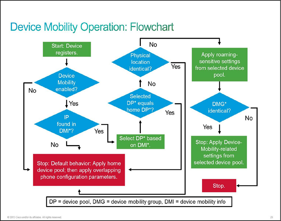
Next, check the phone’s Device Mobility setting. In CCMAdmin, click on Device > Phone and then search for the phone in question. Scroll down to the Device Mobility Mode field and verify that it is On. You can also view the current Device Mobility settings for that device using the hyperlink beside the field. Figure 11-9 shows the Phone Configuration page with this setting.
Figure 11-9. Device Mobility Mode on the Phone
In Figure 11-9, the Device Mobility Mode is indicated by a box. If it is set to Off, change it to On and click Save. If it is set to Default, it is pulling the setting from the service parameter just discussed.
Device Mobility Settings Not Updated
Even when roaming is recognized, odd issues will arise sometimes. At times, the roaming-sensitive settings of a roaming device are properly updated, but the Device Mobility settings are not. This typically goes back to a device pool issue. The Device Mobility Groups of the home device pool and the roaming device pool are different, or the Device Mobility Groups are not set at both device pools. In other words, from the perspective of the Device Mobility–related information in the device pool, it can’t tell what the settings should be (or they’re not set for the roaming device pool). So, they’re not changed. This issue was discussed earlier with the international roaming example.
We return to the crux of the international roaming scenario: If the configuration of the roaming phone is updated, but the user is having issues related to call routing, CoS, CAC, and so on, the underlying cause is likely related to the configuration process. If a portion of the roaming configuration is suppressed and not updated, the roaming device is still reaching back to its home site for some aspects of the configuration.
Troubleshooting call-routing issues, at that point, becomes a practice in merely troubleshooting call routing. The only difference is that the dialing rules and class of service are based on the new settings. The region configuration (codec selection), media resources, SRST reference, calling search space, and/or AAR configuration may be throwing things out of proper alignment. This is what makes it especially important that Device Mobility configuration and planning be in perfect alignment with the overall dial plan design. As mentioned previously, the use of E.164 directory numbers will remedy the bulk of the issues experienced with Device Mobility from a call-routing perspective.
Troubleshooting Device Mobility Configuration Mismatches
For the most part, the issues that impact Device Mobility are configuration related. Although the basic configuration of Device Mobility isn’t overly intense, the design and considerations behind it can be. This is especially true of widespread roaming scenarios, both domestic and international. These configuration issues tend to fall into one of the following categories:
• Codec Mismatch
• CAC Failure/Block
• Media Resource Exhaustion
• SRST Registration Failure During Fallback
When a codec mismatch occurs, the symptom is a phone call between two regions that successfully routes and rings, but when the destination phone answers, the call drops immediately. When this situation occurs, initial troubleshooting involves checking the region configuration set by the device pools for both the source and destination device. If they don’t support the same codec(s), changes may be needed. Other codecs, such as Internet low bit rate codec (iBLC) or OPUS, are often used for mobile clients, third-party clients, and other scenarios to maximize quality in low- or limited-bandwidth situations. In high-bandwidth campus environments, G.722 is often utilized for significantly higher voice quality for calls within a site or campus. Of course, the use of these codecs, too, will necessitate the deployment of transcoding resources.
In terms of Device Mobility, the cause may not always be so straightforward. The same rules apply, but the way the home and remote device pools interact with the roaming devices comes into play.
Recall that the Device Mobility Info entries are configured with a name, IP subnet, and associated device pools. Based on the IP address of the phone, when it registers to CUCM, the determination of whether the device is roaming or home is made. Based on that subnet, CUCM determines the physical location of the phone and assigns specific device pool parameters (the roaming-sensitive settings). Additionally, the local route group and Device Mobility settings are configured unless suppressed.
The region configuration is one of the roaming-sensitive settings. If the IP subnet was not detected as a roaming destination, the device uses its home device pool. The first thing to check is the Device Mobility Info. In fact, all the issues described here can potentially be a result of missing Device Mobility Info association to IP subnets and device pools. Figure 11-10 shows the network topology. It has some additional detail in terms of media resources at each site.
Figure 11-10. Multisite Roaming Topology

In Figure 11-10, each site has its own media resources, which include
• Music on hold (MoH)
• Conference bridging (CFG)
• Media termination point (MTP)
• Transcoding (XCODE)
All these resources should be utilized locally, whenever possible.
In terms of CAC, the CUCM may not know that the phone has changed locations, for whatever reason. It believes the roaming phone is in its home location. So, it proceeds as usual. That means it uses Dallas media resources, the region and location information, and the SRST reference listed in the Dallas device pool. Until it can see that the phone has moved locations, this behavior will continue.
When a call is placed from the roaming phone (which is now in Atlanta) to a phone in the Atlanta site, the call may fail simply due to bandwidth constraints in the WAN coupled with the location/region configuration. This failure may be due to a number of potential scenarios:
• The roaming phone creates an ad hoc conference call with two Atlanta phones. This utilizes the conference resources specified by the Dallas device pool. Most likely, those are going to be in Dallas. This means that the conference will be hosted on the conference bridge in Dallas. So, even though all three phones are local to Atlanta, all three media streams will be routed to the conferencing resource in Dallas and then back to Atlanta. Aside from using WAN bandwidth needlessly, this may introduce voice quality issues for the conference.
• The maximum number of calls allowed across the WAN to the Atlanta location may already be in progress. The idea behind the use of CAC is to protect voice/video traffic from voice/video traffic. You want to make sure that the QoS reserved bandwidth is not exceeded, causing contention for limited resources, thereby resulting in a degraded experience for all calls. When the roaming phone attempts to call an Atlanta phone, even though it’s in Atlanta, CUCM denies the call because it violates the bandwidth utilization parameters specified in the location configuration.
• A call from the roaming phone to another Dallas phone is treated as an intrasite call. This means that the higher bandwidth codec is chosen, using more WAN resources than intended. This call uses higher bandwidth while not being counted against the CAC metrics. This may compromise calls in progress because the QoS traffic types match as critical traffic but may oversubscribe the allocated bandwidth, causing issues for all calls.
• When the roaming user places a call on hold, the MoH comes from the Dallas media resources. This causes additional WAN bandwidth utilization. Also, the codec selection across the WAN may be configured to use G.729 MoH. Obviously, this too is being bypassed because the roaming Dallas phone is using the Dallas MoH Server.
The discussion could go on detailing MTP, transcoding, and other media resources defined in the media resource group list for the device pool. At this point, that would be redundant.
If CUCM becomes unreachable, the roaming phone will become unusable. Of course, this depends on the reason for the CUCM becoming unreachable. If it is due to a WAN outage, and no data path exists between the roaming phone and the Dallas SRST reference, the phone will fail even though the Atlanta phones maintain functionality. The reason is that it is still using the SRST reference specified by the Dallas device pool rather than registering to the Atlanta SRST reference. Again, this is a symptom of the physical location and Device Mobility Info settings being incorrect. This condition may be somewhat more serious, in terms of user impact. In cases in which the incorrect media resources are used, the user may not notice the impact in any way. When the phone becomes unusable, however, it’s a certainty that the user will notice the impact.
Troubleshooting Device Mobility Call-Routing Problems
In the troubleshooting arena, regarding Device Mobility, everything revolves around the proper configuration of the Device Mobility parameters. As mentioned throughout this chapter, E.164 dial plan implementation will correct many of the issues that impact mobility from a call-routing perspective. This includes AAR groups, calling search space, and other similar issues.
AAR is meant to allow for dynamic call rerouting when the primary pathways or gateways become unavailable. For example, when dialing between Dallas and Atlanta using a four-digit dial plan, a Dallas phone might dial 4002 to reach a desired phone. In the event of a WAN outage, AAR prepends the required digits to route the call via the local PSTN voice gateway. So, when a user in Dallas dials 4002 during a WAN outage, AAR reformats the called-party number to 1-707-555-4002, as an example. In other words, the user is not required to change dialing behavior simply due to a WAN outage. That is just another way to protect the user experience and ensure reachability between sites, regardless of the current network conditions.
From a Device Mobility perspective, the AAR group is one of the parameters inherited by the roaming device pool. This means that the parameters applied at one site may or may not pertain to the way a user dials from his or her home site.
AAR configuration aside, globalization or localization configuration is also inherited by the device pool. Phones can originate calls to E.164 numbers, and the IP phones display calling numbers in correct localized format. The globalization and localization procedures are site-dependent because these procedures perform digit manipulations that are based on number formats that are typically used in the PSTN that is close to the site. Therefore, when a phone roams at another site, number globalization and localization processes might not relate to the site in which the phone resides at that moment and might produce incorrect numbers.
For purposes of discussion, an international dial plan is more relevant in terms of network topology and dial plan. The manner in which calling search spaces is implemented is the cause of most call-routing issues. Figure 11-11 shows the call flow decisions made when roaming in an international Device Mobility configuration.
Figure 11-11. Multisite International Roaming Topology

In Figure 11-11 a San Jose phone has roamed to Munich. The San Jose phone is configured with San Jose–specific settings, including San Jose device pool, CSS, AAR CSS, AAR Group, calling party transformations, and called party transformations.
Like San Jose, the Munich site has its own set of specific parameters. That device pool contains the Device Mobility–related information that affects how calls are routed for devices in Munich. The calling search spaces at both sites realize access to partitions relevant to those sites. This includes route patterns, translation patterns, transformation patterns, and localization parameters.
The line CSS does not change, regardless of the phone’s location. However, the device CSS changes based on the location. In making the determination of what changes need to be made for the device to function properly, the Device Mobility Group is checked. If the phone has roamed into a location with the same DMG, all the roaming-sensitive and Device Mobility–related information is replaced with that in the roaming site device pool. Outbound dialing performed by the roaming San Jose phone, in this case, will use the Munich gateway and based on the Munich dial plan. That is, the user must alter the manner in which outbound calls are dialed. For example, whereas the user may typically dial 9 for an outside line, the more commonly used external access digit in Germany is 0. So, the 9 will not work for external calls, as long as the Munich information is in use. AAR functions properly, however.
If the device changes to a different DMG, only the device pool itself is updated. The roaming-sensitive information is suppressed. Outbound dialing performed by the roaming San Jose phone uses the San Jose gateway and dial plan. Additionally, the numbers displayed on the phone may not be in the correct format.
Note
Potential issues in both scenarios can be mitigated, or eliminated, by implementing a full E.164 dial plan in all sites.
Another of the potential issues with mobility call routing stems from the manner in which the line CSS is implemented. The line CSS has a higher priority in the call processing hierarchy than the device-level CSS. Figure 11-12 shows a similar scenario to the last discussion, specifically regarding international roaming.
Figure 11-12. Multisite International Roaming Topology with Line CSS

In Figure 11-12 the line CSS is applied. The San Jose phone brings San Jose–specific line and device parameters when it roams into Munich. The Device Mobility settings configured in the device pool do not have any real impact because they can be applied only at the device level.
When the phone roams to the new site, as with the prior example, the DMG is checked. The configuration applied to the phone depends on whether the DMG has changed. If it has not changed, both the roaming-sensitive settings and the Device Mobility–related information are applied to the device, as expected. However, the line CSS is not altered. And it takes precedence in terms of call processing order. If the line CSS gives the device access to call-routing partitions or CoS partitions, it may bypass the Munich dial plan by routing outbound PSTN calls made by the roaming San Jose phone via the San Jose gateway. Again, this all depends on how the line CSS configuration is implemented.
If the DMG does change, the roaming-sensitive settings and Device Mobility–related information are not be applied to the device. So, the San Jose dial plan remains in play for the phone.
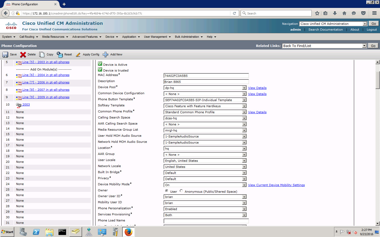
Another common issue that arises in mobility configurations has to do with the use of local route groups. The local route group (LRG) removes the selection of the PSTN gateway from the CSS and adds it to the device pool. The outbound calling features are routed via the configured route group and route list specified by the Local Route Group field in the device pool. The Local Route Group field is located within the roaming-sensitive settings section in the device pool configuration page. Figure 11-13 shows the same topology altered to show the impact of the LRG with mobility.
Figure 11-13. Multisite International Roaming Topology with Local Route Group
Like the prior examples, the DMG is checked and settings applied, or not, based on whether it has changed. If the phones are in the same DMG, all the roaming-sensitive settings and Device Mobility–related info settings are replaced. If the DMGs are different, the outbound PSTN calls utilize the LRG configured in the San Jose device pool. So, the phones are still subject to the San Jose dial plan. In other words, despite the San Jose–specific configuration parameters on the roaming phone, the PSTN calls originating on the phone use the San Jose route group/route list. Also, AAR remains configured with the San Jose–specific configuration. However, if the San Jose dial plan and San Jose AAR CSS permit, and if the AAR group contains the prefix that can be applied in Munich, then AAR can work. Alternatively, if San Jose and Munich use the same AAR group, AAR can work properly. The numbers that are displayed on the phone are likely to be in an incorrect format for the Munich site.
However, if the DMGs are the same, the settings are not replaced. This means that PSTN calls originating from the roaming phone are routed via the local gateway in Munich based on the route group/route list specified in the Munich device pool’s LRG field.
By now, hopefully, it is relatively clear that the manner in which the Device Mobility features are deployed has an immense impact on call routing and the overall user experience. Most of the issues associated with call routing stem from the way CSS configuration is applied, be it at the line level or device level. Additionally, the use of DMGs has a similarly significant impact on the overall functionality.
Troubleshooting Device Mobility Call Privilege Problems
The preceding section briefly examined issues relating to CoS. The issues in call routing also impact calling privileges. This means that phone numbers that a roaming user should be able to dial successfully will fail and/or numbers that should be denied will work. It all comes down to how the DMGs and CSSs are configured for the devices and locations in question.
When a phone roams to another site, it can carry its home site CoS with it. Some companies have varying policies on who can dial where depending on their locale. This is not unusual. However, it might have some less-than-desirable consequences for roaming users. Figure 11-14 shows a sample topology for purposes of this discussion.
Figure 11-14. Troubleshooting Device Mobility Calling Privilege

In Figure 11-14, the policies for each site are noted. Managers in San Jose are able to call internationally. This makes them unique among the two sites in that no one else is allowed to make international calls. When a manager device roams to the Munich office, it should still be able to call international destinations, such as the UK phone noted in the figure. In Figure 11-14, the Munich CoS is blocking the San Jose manager’s attempt to call the UK phone.
The underlying issue comes down to the DMG. Recall that, if the DMG does not change, the roaming site parameters are all inherited for the device. This includes the Device Mobility CSS. In the case of Munich, no CSS includes the capability to call internationally. To avoid inheriting the Device Mobility CSS, the DMG must change. This allows the roaming device to utilize its own San Jose CSS.
Alternately, the line CSS can be utilized because it is not overwritten by the inherited parameters in the mobility configuration. The manager’s CoS should be configured to allow for international calling. When the San Jose manager phone roams to the Munich site, the line CSS will enable it to make the international call.
When you’re figuring out the underlying issue, the Dialed Number Analyzer should be the first tool of choice in finding out why the manager phone is unable to dial the international route pattern(s). Verify the roaming phone’s line and device CSS as well as the one it is supposed to inherit upon roaming. Was the phone able to call internationally prior to roaming? Ensure that the device is configured with the correct CSS, noting the DMG. If these verifications do not render the desired results, call traces may be required. Capture the traces and analyze the resulting logs.
Chapter Summary
Device mobility is a useful feature, especially in today’s mobile workforce. While the configuration may not be complex, the general design contains a good number of potential pitfalls. Understanding how the various components comprising the mobility configuration interact is key to troubleshooting any resulting issues. If the physical locations are different, the roaming-sensitive settings of the device pool are applied. If the DMGs are the same, the Device Mobility–related info settings are applied. The settings related to Device Mobility are really only required when not using a globalized E.164 dial plan. Many potential ailments are utterly avoided when using it.
If the phones are not recognized as roaming devices, the Device Mobility information is key to troubleshooting. The IP subnets must be associated to the device pools in each site to allow devices to be recognized as roaming. Device Mobility mismatches may cause incorrect codec selection, call setup issues, media resource issues, and incorrect SRST reference information.
Mobility call routing is often impacted by incorrect CSS configuration. This can cause incorrect call routing or call failure.
References
For additional information, refer to the following:
• Device Mobility Configuration Overview
https://supportforums.cisco.com/document/77096/device-mobility
• Feature Configuration Guide for Cisco Unified Communications Manager, Release 11.0(1)
Review Questions
Use these questions to review what you’ve learned in this chapter. The answers appear in Appendix A, “Answers to Chapter Review Questions.”
1. The device pool defines which of the following for CUCM registered endpoints?
a. Region
b. Class of service
c. Media resources
d. Route pattern selection
2. Which two sections of the Device Pool Configuration Information page are most relevant to Device Mobility?
a. Device Pool Settings
b. Roaming Sensitive Settings
c. Local Route Group Settings
d. Device Mobility Related Information
3. Which three must be configured in order for Device Mobility to properly function?
a. Physical Location
b. Device Mobility Group
c. Device Mobility Info
d. Mobile Access
4. The Device Mobility Info configuration includes the configuration of which of the following information for each site?
a. IP subnets
b. QoS
c. CoS
d. Local route group
5. Which Device Mobility component is considered the top of the hierarchy in the Device Mobility configuration?
a. Device Mobility Group
b. Physical Location
c. Device Pool
d. Device Mobility Info
6. Which of the following is always updated when a device roams between physical locations?
a. Roaming-sensitive settings
b. Physical location
c. Device Mobility Group
d. Device Mobility Info
7. Which settings within the device pool are only updated when a device roams between Device Mobility Groups?
a. Roaming-sensitive settings
b. Physical location
c. Device Mobility Info
d. Device Mobility Related Information
8. Which of the following should be checked if a roaming device’s site change is not recognized by CUCM?
a. The roaming phone’s IP subnet must have a corresponding Device Mobility Info entry.
b. The roaming phone’s Device Mobility group
c. The roaming phone’s device pool
d. The roaming phone’s class of service
9. Device Mobility is enabled clusterwide in which of the following locations?
a. RTMT
b. Cisco CallManager Service Parameters
c. Enterprise Parameters
d. Device Specific Enterprise Parameters
10. Which of the following are design considerations when implementing Device Mobility?
a. Transcoding (Codec Mismatch)
b. SRST
c. Local route groups
d. Egress gateway