
Simple circuits
Resistors, capacitors and inductors are described as passive components. The currents through them and the p.d.s across them are the result of external currents and p.d.s. They contrast with the active components such as transistors. Before we go further, we look at ways in which the passive components are connected to make useful circuit building blocks.
Potential divider
This consists of two or more resistors wired in series. In Figure A opposite, we have a potential divider made up of ten equal resistors, resistance 1 Ω each. For each resistor, V = IR (p. 25) and, because the same current flows through all of them and they all have the same resistance, I and R are the same for all, making V the same for all. As we go down the chain, the potential drops by the same amount across each resistor. From top to bottom, it drops from V to zero in ten equal steps, each of V/10.
In Figure B there are just two resistors, 3 Ω and 7 Ω. Think of the 3 Ω resistor as being equivalent to three 1 Ω resistors in series. It is equivalent to three of the steps of Figure A. The p.d. across it equals three steps of V/l0, making a drop of 3V/10. Similarly, the drop across the 7 Ω resistor is 7V/10. If V = 20 volts, the drops are 6 V and 14 V respectively.
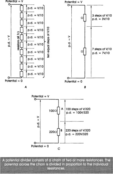
The p.d. across either one of the resistors is proportional to its resistance. In Figure C we have two resistors totalling 320 Ω. These are the equivalent of 320 individual resistors, each of 1 Ω. There are now 320 equal steps, and the p.d. per step is V/320. The p.d.s across the two resistors are:
![]()
If the value of V is 16 volts, the p.d.s across the resistors are (100 × 16)/320 = 5 volts, and (220 × 16)/320 = 11 volts. Once again, the p.d.s are proportional to the resistances.
A circuit such as this, which divides the total p.d. into two or more parts, is called a potential divider. This can be useful in circuits where, for example, the battery provides a p.d. of 6 V but we need a p.d. of 5 V or some other value less than 6 V. A general rule for finding the potential Vjunc at the junction between two resistors A and B is:
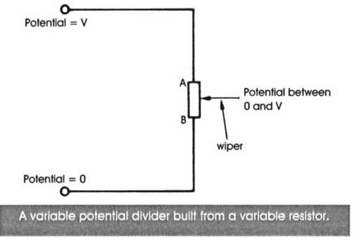
A potential divider can be built from a variable resistor. The two sections of the track on either side of the wiper represent two resistors in series. As the wiper is moved along the track the total resistance (and therefore the number of steps and the p.d. per step) remains unchanged. The potential at the wiper falls smoothly from V when the wiper is at A, to zero when the wiper is at B. This is a way of obtaining any potential within a given range.
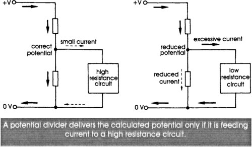
The calculations about potential dividers assume that the same current flows along all the resistors. If another circuit is connected to the divider, this may not be true. If the circuit has very high resistance (left, below) it takes so little current that almost all of the current flowing through A goes on through B. The divider gives the calculated potential. If the connected circuit has low resistance (right, below), most of the current that flows through A goes on to flow through the circuit, and only a small current is left to flow through B. An unexpectedly small current through B means that the p.d. across it is much lower than calculated. This effect may be important when making measurements with test-meters.
Resistor bridge
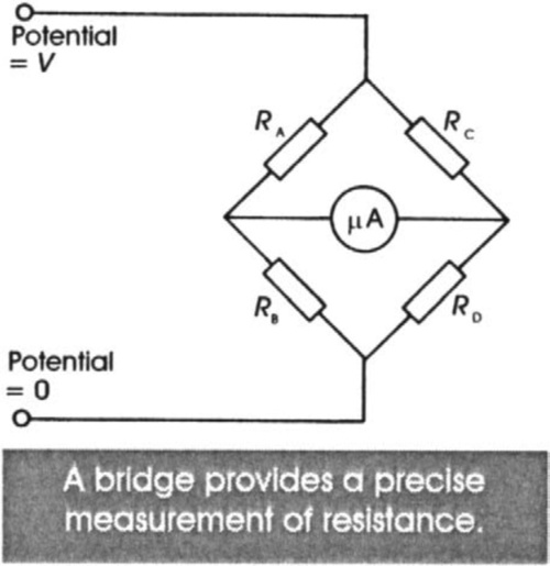
A bridge is made by connecting four resistors as in the figure overleaf. It can be shown by thinking of RA and RB as a potential divider and RC and RD as another potential divider, that if:

then the potential at X is exactly equal to that at Y. We say the bridge is balanced. The milliammeter shows no current flowing between X and Y. The point about using a bridge is that it is very sensitive to being put out of balance. If any one of the values changes even by a small amount, the bridge loses balance and a current flows through the meter.
This type of circuit is used for measuring resistance, with the unknown resistance at RA, a high-precision variable resistor at RB and two high-precision fixed resistors at RC and RD. RB is adjusted until the bridge balances (zero current through the meter). Then, knowing RB, Rc, and RD, the value of RA is calculated. A bridge is often used with resistive sensors, such as strain gauges, and the idea is adaptable to measuring capacitance and inductance.
Filters
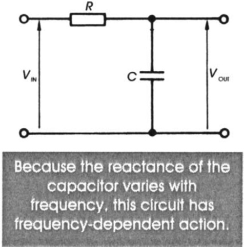
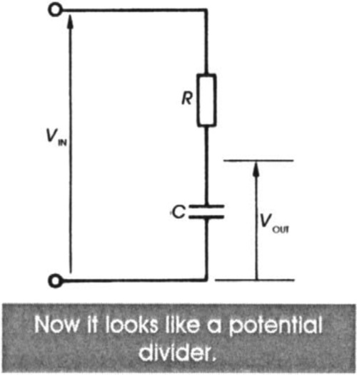
The resistor-capacitor network shown on the left is often used in audio and radio circuits and occasionally in others. If its input VIN is constant, C soon charges to a constant p.d. and the output VOUT settles at a value equal to VIN. The circuit does something more useful when the input is an alternating p.d., amplitude VIN. To see what happens, we re-draw the diagram. Now it has the same arrangement of parts as a potential divider, but with a capacitor replacing the lower resistor. The reactance (equivalent to resistance, p. 52) of the capacitor depends on the frequency of the signal, the alternating p.d. It is high for low frequencies and low for high frequencies.
If the signal has low frequency, the circuit behaves as if it is a potential divider with a very high-value resistor in place of the capacitor.
Example: Suppose that the impedance (= resistance) of R is 1 kΩ. Suppose also that the capacity of C is 100 nF (nanofarad). If VIN is an alternating signal of 1 kHz with an amplitude of 1 V, the graphs of VIN and VOUT look like this:
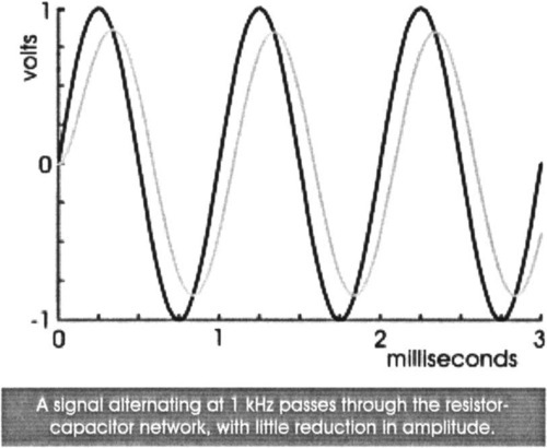
The signal VIN (black curve) with a frequency of 1 kHz takes 1 ms to complete a cycle. The output signal VOUT (grey curve) has exactly the same frequency, and its amplitude about 840 mV. It has passed through the network with only a small amount of loss. This is because C has a relatively high impedance at that frequency. It is behaving as if it is a resistor of relatively high value.
This is what happens if we keep the same components values but increase the frequency of the signal by ten times to 10 kHz:
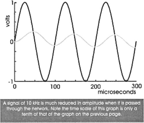
The grey curve shows that the amplitude of VOUT is now reduced (or attentuated) to about 157 mV. This is explained by the fact that the impedance of the capacitor is reduced as frequency is increased. Now only a relatively small p.d. can develop across it. Note that the frequency of VOUT is still equal to that of VIN.
The graphs illustrate the action of the network at frequencies of 1 kHz and 10 kHz. Below 1 kHz the impedance of C is even higher than at 1 kHz and the amplitude of VOUT is very close to 1 V. At an extremely high frequency the impedance of C is very small. It is almost a short-circuit and VOUT is very close to zero. The overall effect is that low-frequency signals appear strongly at the output of the network, but high-frequency signals are lost. We describe this network as a low-pass filter. More exactly, frequencies below a certain level, known as the cut-off frequency, pass through the filter with very little attenuation. But there is progressive reduction in amplitude above the cut-off frequency. The way the amplitude varies with frequency is shown in detail on page 202.
Because it uses only passive components (see the start of this chapter), this resistor-capacitor network is more aptly described as a passive low-pass filter. Later, we shall describe some active filters.
Filtering affects not only the amplitude of the signal at different frequencies but also the timing or phase of the output signal with respect to the input signal. This is because of the time factor involved in charging and discharging the capacitor. The sine wave of the output signal is still a sine wave and has the same frequency as the input signal, but its cycles begin and end a little bit later than those of the input signal. The delay in the graph on page 63 is approximately 90 μs, or just under one tenth of a cycle. At the cut-off frequency (1.6 kHz for this network), the output signal is an eighth of a cycle behind the input signal. As frequencies increase further, the output signal lags further and further behind the input signal until it is a quarter-cycle behind.
Another type of filter is obtained if we exchange the positions of the resistor and the capacitor in the network. Now high-frequency signals pass freely through the circuit but low-frequency signals are much attenuated. This is a high-pass passive filter.
This simple description is only an outline of the working of resistor-capacitor filters. We have seen that a filter affects not only the amplitude of the output signal but also its phase in relation to that of the input signal. The same principles apply to a filter made from a resistor and inductor or from a capacitor and an inductor. As might be expected, a filter like that on page 62, but with an inductor instead of the capacitor has the opposite response to frequency. It is a high-pass filter.
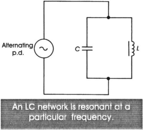
Resonance
This circuit is very sensitive to the effects of frequency. If the input to the circuit is a low-frequency signal, it is mainly blocked by the capacitor. But it passes easily through the inductor, which acts as a short circuit. The impedance of the capacitor-inductor network is very low impedance and only small p.d.s are developed across it.
If the input to the network is a high-frequency signal, it passes readily through the capacitor but not through the inductor. As before, the impedance of the capacitor-inductor network is very low impedance and only small p.d.s are developed across it.
However, at one intermediate frequency, depending on the values of capacitance and inductance, the capacitor and inductor offer equal reactance to the signal. Then the signal has maximum effect on the circuit, and the swings of p.d. across it are at a maximum. When the signal source is oscillating at this frequency, the circuit is said to resonate.
At the resonant frequency it is not necessary to supply large quantities of energy to make it oscillate. In fact, even if the signal source is removed, it will continue to resonate for a while, until the oscillations die out. The action is very like that of pushing a child on a swing. The swing has a natural frequency which depends on its length. As the child swings to and fro we give it a small push every time the child is swinging away from us. Gradually, the amplitude of swinging increases, because each time we push we are reinforcing the natural motion of the swing. When the person is at the extremes of the swinging, at the highest points above ground, energy is stored in the person as potential energy. When the person is at the lowest point of the swinging the potential energy is gone, and is converted to energy of motion. As the swing oscillates to and fro, energy is converted from potential energy to energy of motion (kinetic energy) and back again repeatedly.
A capacitor-inductor circuit is like a swing. Imagine the capacitor fully charged in a given direction. It is storing energy in the form of the electric field produced by the stored charge. Then the capacitor discharges through the inductor, losing energy itself but building up a store of energy in the inductor in the form of its magnetic field. At a certain point the capacitor is fully discharged and the inductor holds its maximum energy. With no further current from the discharged capacitor the magnetic field in the inductor begins to collapse. However, self induction (p. 51) ensures that a current continues to flow through the inductor in the same direction as before. This recharges the capacitor but in the opposite direction. Eventually the field has completely collapsed and a charge has built up in the capacitor. Once again all the energy is stored in the capacitor.
At this point, the capacitor is fully charged but in the opposite direction. With no further change in the magnetic field, no more current flows into the capacitor. It begins to discharge through the inductor and the process repeats, but with charge, currents and fields in the opposite direction. There is repeated conversion of energy from electric field to magnetic field and back again.
If there were no loss due to resistance of the wires of the inductor and connections, and if there were no small losses in the dielectric of the capacitor, the oscillations described above would go on for ever.
A resonant circuit can build up large swings of p.d. from very small beginnings. Starting with a minute amount of energy in the electric or magnetic field, small oscillations will occur as described above. If an external source supplies energy from outside at just the right frequency (like the person pushing the swing at just the right instant), a little extra energy is added to the system at each oscillation. The energy levels build up gradually until the circuit is oscillating strongly. This is the principle on which certain types of oscillators work (p. 177) and also that of the tuning circuits of radio receivers (p. 273).