Resistance, Inductance, and Capacitance in AC Circuits
Alternating current electronic circuits are similar in many ways to direct current (dc) circuits. AC circuits are classified by their electric characteristics (resistive, inductive, or capacitive). All electronic ac circuits are resistive, inductive, capacitive, or a combination of these characteristics. The operation of each type of electronic circuit is different. The nature of ac causes certain circuit properties to exist.
Important Terms
The following terms provide a review of resistance, inductance, and capacitance in ac circuits:
Admittance (Y) The total abilityofan ac circuit toconduct current, measured in siemens (S) or ohms (Ω); the inverse of impedance: Y = 1/Z.
Angle of lead or lag The phase angle between applied voltage and total current flow in an ac circuit (in degrees). In an inductive circuit, voltage leads current; in a capacitive circuit, voltage lags current.
Apparent power (volt-amperes) The power delivered to an ac circuit; applied voltage times total current in an ac circuit.
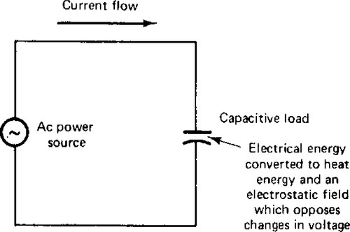
Capacitance (C) The property of a circuit or device to oppose changes in voltage due to energy stored in an electrostatic field.
Capacitive reactance (Xc) The opposition to the flow of ac current caused by a capacitive device (measured in ohms [Ω]).
Capacitor A device that has capacitance and usually is made of two metal plates separated by a dielectric material (insulator).
Conductance (G) The ability of the resistance of an ac circuit to conduct current, measured in siemens (S) or mhos; the inverse of resistance: G = 1/R.
Dielectric The insulating material placed between the metal plates of a capacitor.
Dielectric constant A number that represents the ability of a dielectric material to develop an electrostatic field compared with air, which has a value of 1.0.
Electrolytic capacitor A capacitor that has a positive plate made of aluminum and a dry paste or liquid used to form the negative plate.
Electrostatic field The field developed around a material because of the energy of an electric charge, as is exhibited by capacitors.
Farad (F) The unit of measurement of capacitance; produced when a charge of 1 coulomb (C) causes a potential of 1 V to be developed across two points.
Henry (H) The unit of measurement of inductance; produced when a voltage of 1 V is induced as the current through a coil is changing at a rate of one ampere per second.
Impedance (Z) The total opposition to current flow in an ac circuit, a combination of resistance (R) and reactance (X) in a circuit (measured in ohms [Ω]):
![]()
Inductance (L) The property of a circuit to oppose changes in current due to energy stored in a magnetic field.
Inductive circuit A circuit that has one or more inductors or has the property of inductance, such as an electric motor circuit.
Inductive reactance (XL) The opposition to current flow in an ac circuit caused by an inductance (L); measured in ohms [Ω]: XL = 2π × f × L
Inductors Coils of wire or windings that possess the property of inductance and are used in a circuit to cause inductance to be present.
Lagging phase angle The angle by which current lags voltage (or voltage leads current) in an inductive circuit.
Leading phase angle The angle by which current leads voltage (or voltage lags current) in a capacitive circuit.
Mho Ohm spelled backward; a unit of measurement for conductance, susceptance, and admittance in ac circuits that is being replaced by the unit siemen (S).
Mica capacitor A capacitor made of metal foil plates separated by a mica dielectric.
Mutual inductance (M) The situation in which two coils are located close together so that the magnetic fluxes of the coils affect one another in terms of total inductance properties.
Power factor (pf) The ratio of power converted (true power) in an ac circuit and the power delivered to the circuit.
Radian The measure of an angle formed by rotating the radius of a circle until the arc made by the end of the radius is the same length as the radius; 1 radian (rad) = 57.3°; the circumference of a circle is 2π (6.28) radians.
Reactance (X) The opposition to current flow in an ac circuit caused by inductance (inductive reactance, XL) or capacitance (capacitive reactance, XC).
Reactive circuit An ac circuit that has the property of inductance or capacitance or both.
Reactive power (VAR) The “unused” power of an ac circuit that has inductance or capacitance; the power absorbed by the magnetic or electrostatic field of a reactive circuit.
Resistance The opposition to current flow in a circuit caused by a resistive device.
Resistive circuit A circuit in which the only opposition to current flow is resistance; a nonreactive circuit.
Siemen (S) See mho.
Susceptance (B) The ability of inductance (BL) or capacitance (BC) to pass ac current; measured in siemens or mhos; BL = 1/XL and BC = 1/XC.
True power (watts) The power actually converted to another form of energy in an ac circuit.
VAR (volt-amperes-reactive) The unit of measurement of reactive power.
Vector A straight line that indicates a quantity with magnitude and direction.
Volt-ampere (VA) The unit of measurement of apparent power.
Working voltage A rating of capacitors; the maximum voltage that can be placed across the plates of a capacitor without damage.
Resistive AC Circuits
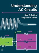
The simplest type of ac circuit is a resistive circuit, such as the one shown in Fig. 3-1. The purely resistive circuit offers the same type of opposition to ac as it does to pure dc sources. In dc circuits, the following relations exist:
![]()

![]()
These basic electric relations show that when voltage is increased, the current in the circuit increases proportionally. As resistance is increased, the current in the circuit decreases. The waveforms in Fig. 3–2 show that the voltage and current in a purely resistive circuit with ac applied are in phase. An in-phase relation exists when the minimum and maximum values of both voltage and current occur at the same time interval. The power converted by the circuit is a product of voltage times current (P = V × I). The power curve is shown in Fig. 3–3. The behavior of an ac circuit that contains only resistance is very similar to that of a dc circuit. Purely resistive circuits are seldom encountered in the design of electric power systems, although some devices are primarily resistive in nature.


Inductive Circuits
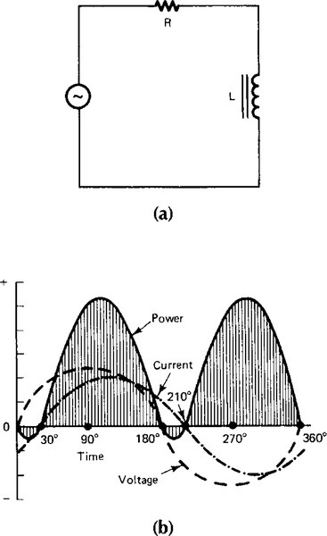
The property of inductance (L) is commonly encountered in electronic circuits. This circuit property, shown in Fig. 3–4, adds more complexity to the relation between voltage and current in an ac circuit. All motors, generators, and transformers exhibit the property of inductance. This property is evident because of a counter- electromotive force (CEMF), which is produced when a magnetic field is developed around a coil of wire. The magnetic flux produced around the coils affects circuit action. Thus the inductive property (CEMF) produced by a magnetic field offers opposition to change in the current flow in a circuit.

The opposition to change of current is evident in Fig. 3-4b. In an inductive circuit, voltage leads current or current lags voltage. In a purely inductive circuit (contains no resistance), voltage leads the current by 90° (Fig. 3-5), and no power is converted in the circuit. However, because all actual circuits have resistance, the inductive characteristic of a circuit might typically cause the condition shown in Fig. 3–6. The voltage is leading the current by 30°. The angular separation between voltage and current is called the phase angle. The phase angle increases as the inductance of the circuit increases. This type of circuit is called a resistive- inductive (RL) circuit.
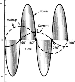
In terms of power conversion, a purely inductive circuit does not convert any power in a circuit. All ac power is delivered back to the power source. Refer to Fig. 3–5 and look at points A and B on the waveforms. These points show that at the peak of each waveform, the corresponding value of the other waveform is zero. The power curves shown are equal and opposite in value and cancel each other out. When both voltage and current are positive, the power is positive because the product of two positive values is positive. When one value is positive and the other is negative, the product of the two values is negative; therefore the power converted is negative. Negative power means that electric energy is being returned from the Ioad device to the power source without being converted to another form of energy. Therefore the power converted in a purely inductive circuit (90° phase angle) equals zero.
Compare the purely inductive waveforms of Fig. 3–5 to those of Fig. 3–6. In the practical RL circuit, part of the power supplied from the source is converted in the circuit. Only during the intervais from 0° to 30° and from 180° to 210° does negative power resuit. The remainder of the cycle produces positive power; therefore, most of the electric energy supplied by the source is converted to another form of energy.
Any inductive circuit exhibits the property of inductance (L), which is the opposition to a change in current flow in a circuit. This property is found in coils of wire (inductors) and in rotating machinery and transformer windings. Inductance also is present to some extent in electric power transmission and distribution lines. The unit of measurement for inductance is the henry (H). A circuit has 1 H of inductance when a current change of 1 ampere per second (A/s) produces an induced CEMF of 1 V.
In an inductive circuit with ac applied, an opposition to current flow is produced by the inductance. This type of opposition is known as inductive reactance (XL). The inductive reactance of an ac circuit depends on the inductance (L) of the circuit and the rate of change of current. The frequency of the applied ac establishes the rate of change of the current. Inductive reactance (XL) may be expressed as follows:
![]()
XL = the inductive reactance in ohms (Ω)
2π = 6.28, the mathematical expression for one sine wave of ac (0°–360°)
f = the frequency of the ac source in hertz (Hz)
L = the inductance of the circuit in henrys
Mutual Inductance
When inductors are connected together, a property called mutual inductance (M) must be considered. Mutual inductance is the magnetic field interaction or flux linkage between coils. The amount of flux linkage is called the coefficient of coupling (k). If all the lines of force of one coil eut across a nearby coil, the condition is called unity coupling. There are many possibilities, and they are determined by coil placement of coupling between coils. The amount of mutual inductance between coils is found with the following formula:
![]()
The term k is the coefficient of coupling, which gives the amount of coupling. L1 and L2 are the inductance values of the coils. Mutual inductance should be considered when two or more coils are connected together.
Inductors in Series and Parallel
Inductors may be connected in series or parallel. When inductors are connected to prevent the magnetic field of one from affecting the others, these formulas are used to find total inductance (LT).
![]()
2. Parallel inductance
where L1, L2, L3, ... are inductance values measured in henrys.
When inductors are connected so that the magnetic field of one affects the other, mutual inductance increases or decreases total inductance. The effect of mutual inductance depends on the physical positioning of the inductors. The distance apart and the direction in which they are wound affect mutual inductance. Inductors are connected in series or parallel with an aiding or opposing mutual inductance (M). The following formulas are used to find total inductance (LT):
![]()
2. Series opposing
![]()
3. Parallel aiding

4. Parallel opposing
L1 and L2 are the inductance values, and M is the value of mutual inductance.
Capacitive Circuits
Figure 3-7 shows a capacitive device connected to an ac source. Whenever two conductive materials (plates) are separated by an insulating (dielectric) material, the property of capacitance is exhibited. Capacitors can store an electric charge. They also have many applications in electric power systems.
The operation of a capacitor in a circuit depends on its ability to charge and discharge. When a capacitor charges, an excess of electrons (negative charge) accumulates on one plate and a deficiency of electrons (positive charge) occurs on the other plate. Capacitance (C) is determined by the area of the conductive material, the thickness of the dielectric, and the type of insulating material. Capacitance is directly proportional to the plate area and inversely proportional to the distance between the plates. These factors are expressed with the following formula:

where C is capacitance in picofarads (pF), k is the dielectric constant, a is the area of one plate in square centimeters (cm2), and t is the dielectric thickness in centimeters (cm).
Example
Compute the capacitance of a capacitor that has two metal foil plates that are 2.5 m wide and 250 cm long. The dielectric material is wax paper. Wax paper has a dielectric constant of 2. The thickness of the wax paper is 0.025 cm.
Substituting these values in the capacitance formula gives the following:
The fundamental unit of capacitance is the farad (F). A capacitance of 1 F results when a potential of 1 V causes an electric charge of 1 coulomb (C) to accumulate on a capacitor. Because a farad is a very large unit, measurements in microfarads (μF) and picofarads (pF) are ordinarily assigned to capacitors.
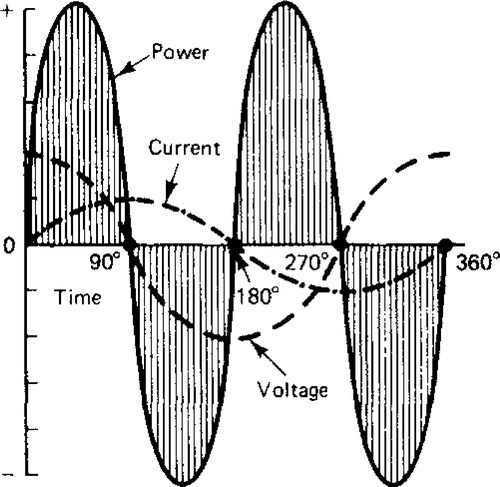
If a dc is applied to a capacitor, the capacitor charges to the value of that dc voltage. After the capacitor is fully charged, it blocks the flow of dc. However, if ac is applied to a capacitor, the changing value of current causes the capacitor alternately to charge and discharge. In a purely capacitive circuit, the situation shown in Fig. 3-8 would exist. The greatest amount of current would flow in a capacitive circuit when the voltage changed most rapidly. The most rapid change in voltage occurs at the 0° and 180° positions, where polarity changes. At these positions, maximum current is developed in the circuit. When the rate of change of the voltage value is slow, such as near the 90° and 270° positions, a small amount of current flows. Figure 3-8 shows that current leads voltage by 90° in a purely capacitive circuit and that voltage lags current by 90°. Because a 90° phase angle exists, no power would be converted in this circuit, just as no power was developed in the purely inductive circuit. As shown in Fig. 3-9, the positive and negative power waveforms cancel one another.

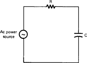
Because all circuits contain some resistance, a more practical circuit is the resistive-capacitive (RC) circuit shown in Fig. 3-10. In an RC circuit, current leads voltage by a phase angle between 0° and 90°. As capacitance increases with no corresponding increase in resistance, the phase angle becomes greater. The waveforms of Fig. 3-11 show an RC circuit in which current leads voltage by 30°. This circuit is similar to the RL circuit in Fig. 3-6. Power is converted in the circuit except during the 0° to 30° interval and the 180° to 210° interval. In the RC circuit shown, most of the electric energy supplied by the source is converted to another form of energy in the Ioad.

Because of the electrostatic field that develops around a capacitor, an opposition to the flow of ac exists. This opposition is known as capacitive reactance (XC). Capacitive reactance is expressed as follows:
XC = capacitive reactance in ohms
2π = the mathematical expression of one sine wave of ac (0 - 360°)
f = the frequency of the source in hertz
C = the capacitance in farads
Capacitors in Series
Adding capacitors in series has the same effect as increasing the distance between plates. This reduces total capacitance. Total capacitance (CT) is found in the same way as parallel resistance. The reciprocal formula is used, as follows:
Capacitors in Parallel
Capacitors in parallel resemble one capacitor with its plate area increased. Doubling plate area doubles capacitance. Capacitance in parallel is found by adding individual values, just as with series resistors:
![]()
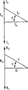
Vector (Phasor) Diagrams
Figure 3-12 shows a vector diagram for each circuit condition. Vectors are straight lines that have a specific direction (angle with respect to a reference direction) and length (magnitude). They may be used to represent voltage or current values. An understanding of vector diagrams (sometimes called phasor diagrams) is important when dealing with ac. Rather than using waveforms to show phase relations, it is possible to use a vector or phasor representation.
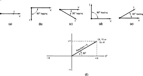
Ordinarily when beginning a vector diagram one draws a horizontal line with its left end as the reference point. Rotation in a counterclockwise direction from the reference point is considered a positive direction. In the diagrams in Fig. 3-12, the voltage vector is the reference. For inductive circuits, the current vector is drawn in a clockwise direction, indicating a lagging condition. A leading condition is shown for the capacitive circuits through use of a current vector drawn in a counterclockwise direction from the voltage vector.
Vectors and Coordinate Systems
Many ac circuit problems require the use of vectors and coordinate systems. An arrowhead is used on the end of the vector to indicate the direction toward which a force is acting. Most vector analysis deals with determining the magnitude and direction of a resultant vector produced by two or more similar vectors acting on a point (see Fig. 3-12).
Rectangular Coordinate System
A rectangular coordinate system is useful when the rectangular components of a vector are needed. The rectangular components can be read directly by means of observing or measuring the horizontal component, X, and the vertical component, Y. The coordinates of the resultant vector in Fig. 3-12f are (X, Y).
Polar Coordinate System
A polar coordinate system is most useful when the magnitude and direction of the vector are required. The magnitude ρ (Greek letter rho) is given directly by the length of the vector. The direction is given as the angle θ (Greek letter theta). The resultant vector in Fig. 3-12f is represented as ρ ∠θ or 5 ∠30°. The Z symbol represents an angle. The example is read as 5 at an angle of 30°.
Series AC Circuits
In any series ac circuit, the current is the same in all parts of the circuit. The voltages must be added with a voltage triangle. The impedance (Z) of a series ac circuit is found with an impedance triangle. Power values are found with a power triangle.
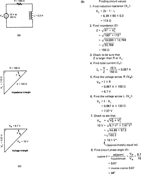
Series RL Circuits
Series RL circuits often are present in electronic equipment. When an ac voltage is applied to a series RL circuit, the current is the same through each part. The voltage drops across each component are distributed according to the values of resistance (R) and inductive reactance (XL) in the circuit.
The total opposition to current flow in any ac circuit is called impedance (Z). Both resistance and reactance in an ac circuit oppose current flow. The impedance of a series RL circuit is found with either of the following formulas:
![]()
or
![]()
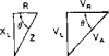
The impedance of a series RL circuit is found with the impedance triangle. This right triangle is formed by the three quantities that oppose ac. A triangle also is used to compare voltage drops in series RL circuits. Inductive voltage (VL) leads resistive voltage (VR) by 90°. VA is the voltage applied to the circuit. Because these values form a right triangle, the value of VA may be found with the following formula:
![]()
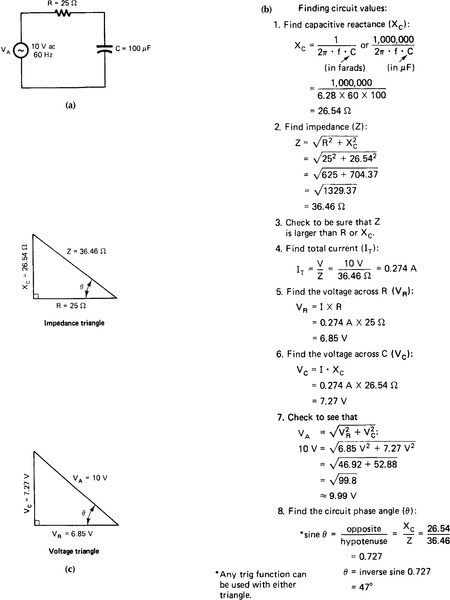
An example of a series RL circuit is shown in Fig. 3-13. Appendix B should be reviewed, if necessary, to gain a better understanding of trigonometry for ac circuit problems.
Series RC Circuits
Series RC circuits have many uses. This type of circuit is similar to a series RL circuit. In a capacitive circuit, current leads voltage. The reactive values of RC circuits act in the opposite directions to RL circuits. An example of a series RC circuit is shown in Fig. 3-14.
Series RLC Circuits
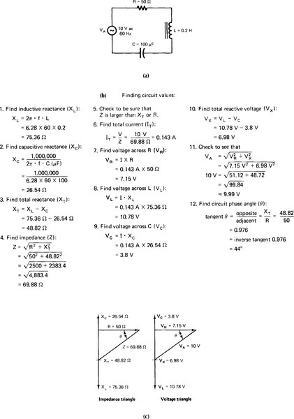
Series RLC circuits have resistance (R), inductance (L), and capacitance (C). The total reactance (XT) is found by means of subtracting the smaller reactance (XL or XC) from the larger one. Reactive voltage (VX) is found by means of obtaining the difference between VL and Vc. The effects of capacitance and inductance are 180° out of phase with each other. Right triangles are used to show the simplified relations of the circuit values. An example of a series RLC circuit is shown in Fig. 3-15.
PARALLEL AC CIRCUITS
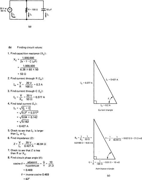
Parallel ac circuits have many applications. The basic formulas used with parallel ac circuits are different from those used with series circuits. The impedance (Z) of a parallel circuit is less than individual branch values of resistance, inductive reactance, or capacitive reactance. There is no impedance triangle for parallel circuits because Z is smaller than R, XL, or Xc. A right triangle is drawn to show the currents in the branches of a parallel circuit.
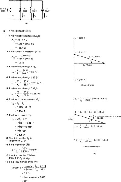
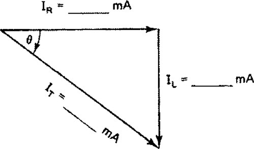
The voltage of a parallel ac circuit is the same across each branch. The currents through the branches of a parallel ac circuit are shown with a right triangle called a current triangle. The current through the capacitor (IC) is shown leading the current through the resistor (IR) by 90°. The current through the inductor (IL) is shown lagging lR by 90°. IL and IC are 180° out of phase. They are subtracted to find the total reactive current (IX). Because these values form a right triangle, the total current may be found with the following formula:
![]()
This method is used to find currents in parallel RL, RC, or RLC circuits.
When components are connected in parallel, finding impedance is more difficult. An impedance triangle cannot be used. A method that can be used to find impedance is to use an admittance triangle. The following quantities are plotted on the triangle: admittance: Y = 1/Z; conductance: G = 1/R; inductive susceptance: BL = 1/XL; and capacitive susceptance: BC = 1/XC. These quantities are the inverse of each type of opposition to ac. Because total impedance (Z) is the smallest quantity in a parallel ac circuit, its reciprocal (1/Z) becomes the largest quantity on the admittance triangle (just as ½ is larger than ¼). The values are in siemens (S) or mho (ohm spelled backward).
Parallel ac circuits are similar in several ways to series ac circuits. Study the examples of Figs. 3-16 through 3-18.

Power in AC Circuits
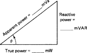
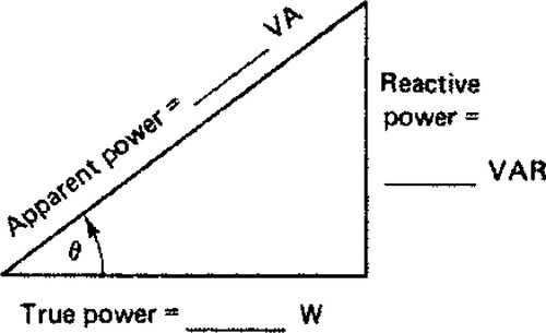
Power values in ac circuits are found with power triangles, as shown in Fig. 3-19. The power delivered to an ac circuit is called apparent power. It equals voltage times current. The unit of measurement is the volt-ampere (VA) or kilovolt-ampere (kVA). Meters are used to measure apparent power in ac circuits. Apparent power is the voltage applied to a circuit multiplied by the total current flow. The power converted to another form of energy by the Ioad is measured with a wattmeter. This actual power converted is called true power. The ratio of true power converted in a circuit to apparent power delivered to an ac circuit is called the power factor (pf). The power factor is found with the following formula:

or
![]()
W is the true power in watts and VA is the apparent power in volt-amperes. The highest power factor of an ac circuit is 1.0, or 100%. This value is called the unity power factor.
The phase angle (θ) of an ac circuit determines the power factor. The phase angle is the angular separation between voltage applied to an ac circuit and current flow through the circuit. More inductive or capacitive reactance causes a larger phase angle. In a purely inductive or capacitive circuit, a 90° phase angle causes a power factor of 0°. The power factor varies according to the values of resistance and reactance in a circuit.
Two types of power affect power conversion in ac circuits. Power conversion in the resistive part of the circuit is called active power, or true power. True power is measured in watts (W). The other type of power is caused by inductive or capacitive loads. lt is 90° out of phase with the true power and is called reactive power. It is a type of unused power. Reactive power is measured in volt-amperes reactive (VAR).
The power triangles of Fig. 3-19 have true power (W) marked as a horizontal line. Reactive power (VAR) is drawn at a 90° angle from the true power. Volt-amperes or apparent power (VA) is the longest side (hypotenuse) of the right triangle. This right triangle is similar to the impedance triangle and the voltage triangle for series ac circuits and the current triangle and admittance triangle for parallel ac circuits. Each type of right triangle has a horizontal line marking the resistive part of the circuit. A vertical line is used to mark the reactive part of the circuit. The hypotenuse is used to mark total values of the circuit. The length of the hypotenuse depends on the amount of resistance and reactance in the circuit. Vector diagrams and right triangles are extremely important for understanding ac circuits.
We can further examine the power relations of a power triangle by expressing each value mathematically on the basis of the value of apparent power (VA) and the phase angle (θ). The phase angle is the amount of phase shift, in degrees, between voltage and current in the circuit. Trigonometrie ratios, which are discussed in appendix B, show that the sine of an angle of a right triangle is expressed as follows:

Because this is true, the phase angle can be expressed as follows:
Therefore
![]()
The phase angle and VAR can be determined with trigonometric ratios. The cosine of an angle of a right triangle is expressed as follows:
Thus in terms of the power triangle:
Therefore true power can be expressed as follows:
![]()
The following expression

is the power factor of a circuit; therefore the power factor is equal to the cosine of the phase angle (pf = cosine θ).
Self-Examination
Inductance and Inductive Reactance
Solve the following problems, which deal with inductance and inductive reactance:
1. Total inductance in series: L1= 2 H, L2 = 3 H, L3 = 2 H, LT= _____ H.
2. Total inductance in parallel: L1 = 2 H, L2 = 3 H, L3 = 8 H, LT= _____ H.
Find the inductive reactance for the following:
4. 50 Hz, 2 H, XL = _____.Ω
5. 60 Hz, 1 H, XL = _____.Ω
6. 40 Hz, 3H, XL = _____.Ω
Find the mutual inductance in series to increase inductance (field aiding):
7. L1 = 2 H, L2 = 5 H, M = 0.55
LT = L1 + L2 + 2 M = ______ H
8. L1 = 3 H, L2 = 2 H, M = 0.35
LT = _____ H
Find the mutual inductance in series to decrease inductance (fields opposing):
9. L1 = 4 H, L2 = 3 H, M = 0.85
LT = L1 + L2 − 2, M = ______ H
10. L1 = 3 H, L2 = 3 H, M = 0.4
LT = _____ H
Compute the following problems when the inductors are connected in parallel. Use the values of the previous problem.
12. LT = ______ H
13.

14. LT = ______ H
Capacitance and Capacitive Reactance
Solve the following problems, which deal with capacitance and capacitive reactance.
Compute the capacitance for the following capacitors, using the formula
where C is capacitance in picofarads, k is the dielectric constant, a is the plate area in square centimeters, and t is the thickness of the dielectric in centimeters.
15. Dielectric constant = 3; area of plate = 2 × 200 cm; and thickness of dielectric = 0.03 cm: C = ______ pF
16. Dielectric constant = 3; area of plate = 3 × 200 cm; and thickness of dielectric = 0.04 cm: C = ______ pF
17. Dielectric constant = 2; area of plate = 0.25 × 275 cm; and thickness of dielectric = 0.02 cm: C = ______ pF
Compute the following for the total capacitance in a series circuit using the following formula:
18. C1 = 10 μF, C2 = 10 μF, C3 = 30 μF, CT = ______ μF
19. C1 = 40 μF, C2 = 20 μF, C3 = 20 μF, CT = ______ μF
20. C1 = 80 μF, C2 = 60 μF, C3 = 80 μF, CT = ______ μF
21. Compute the capacitive reactance for a 60 Hz ac circuit with a 30 μF capacitor: Xc = ______ ohms.
Compute the following for total capacitance in parallel:
22. C1 = 80 μF, C2 = 60 μF, C3 = 80 μF, CT = _____ μF
23. C1 = 50 μF, C2 = 20 μF, C3 = 30 μF, CT = _____ μF
24. C1 = 70 μF, C2 = 50 μF, C3 = 80 μF, CT = _____ μF
Series and Parallel AC Circuits
Solve each of the following series and parallel ac circuit problems.
A 20 μF capacitor and a 1000 Ω resistor are connected in series with a 120 V, 60 Hz ac source. Find each of the following values:
26. True power = _____ W
27. Z = ______ Ω
28. Apparent power = ______ VA
29. I = ______ mA
30. Reactive power = _______ VAR
31. VC = ______ V
32. Power factor = ______ %
33. VR = _____ V
34. Draw an impedance triangle, a voltage triangle, and a power triangle for the values of Problems 25 through 33 and label each value.
A parallel ac circuit converts 12,000 W of power. The applied voltage is 240 V and the total current is 72 A. Find each of the following values:
35. Apparent power = ______ VA
36. Power factor = _______ %
37. Phase angle of circuit = ______ °
38. Draw a power triangle for the values of problems 35 through 37 and label each value.
A series circuit with 20 V, 60 Hz applied has a resistance of 100 Ω, a capacitance of 40 μF, and an inductance of 0.15 H. Find each of the following values.
40. VC = ______ V
41. XL = ______ Ω
42. VL = _______ V
43. XT = _______ Ω
44. VR = ______ V
45. Z = _______ Ω
46. Phase angle = ______ °
47. I = ______ mA
48. Draw an impedance triangle and a voltage triangle for the circuit of the previous problem and label each value.
Use the values given for R, C, and L in problems 39 through 47. Connect them in a parallel circuit that has 10 V applied to it.
Then find each value.
50. Conductance = _______ S
51. IC = ______ mA
52. Susceptance = _______ S
53. IL= ______ mA
54. Admittance = ______ S
55. IT = _____ mA
56. Phase angle = _______ °
57. Z = ______ Ω.
58. Draw a current triangle and an admittance triangle and label each value for the circuit of problems 49 through 57.
Complete the following sentences:
59. The property of an electric circuit that tends to prevent a change in current is called _____________________.
60. The letter symbol for inductance is _____________________.
61. Inductance is measured in _____________________.
62. A coil used to add inductance into an ac circuit is called a(n) _____________________.
63. The opposition to current flow caused by inductance is called _____________________.
64. The letter symbol for inductive reactance is _____________________.
65. Inductive reactance is measured in _____________________.
66. The total opposition to current flow in an ac circuit is called _____________________.
67. The letter symbol for impedance is _____________________.
68. Impedance is measured in _____________________.
69. The relation in electric degrees of voltage and current in an ac circuit is called _____________________.
70. In a purely inductive circuit, current _____________________ voltage by _____________________ °.
71. In an ac circuit containing both resistance and inductance, current _____________________ voltage by _____________________ voltage by _____________________ through _____________________°.
72. Maximum effective voltage multiplied by maximum effective current equals _____________________ power.
73. Apparent power is measured in _____________________.
74. The power consumed by the resistance in an ac is called the _____________________ power.
75. True power is measured in _____________________.
76. The ratio of true power to apparent power is called _____________________.
77. Power factor is expressed as a(n) _____________________ or a(n) _____________________.
78. Apparent power multiplied by power factor equals _______________________.
Answers
2. 1.047
3. 1507.2
4. 628
5. 376.8
6. 753.6
7. 8.1
8. 5.7
9. 5.3
10. 5.2
11. 1.748
12. 1.38
13. 1.278
14. 1.3
15. 3540
16. 3982.5
17. 608.43
18. 4.29
19. 8 μF
20. 24.04
21. 88.46
22. 220
23. 100
24. 170
25. 132.7
26. 14.16
27. 14.16
28. 1008
29. 14.28
30. 119
31. 1.88
32. 99%
33. 119
34. ![]()
35. 17,280
36. 69%
37. 46.37
38. ![]()
39. 66.35
40. 13.2
41. 56
42. 11.25
43. 9.83
44. 19.9
45. 100.48
46. 5.73°
47. 199
48. 
49. 100
50. 0.01
51. 150
52. 0.0177
53. 177
54. 0.0104
55. 103.6
56. 15.15°
57. 96.5
58. 
59. Inductance
60. L
61. Henrys
62. Inductor
63. Inductive reactance
64. XL
65. Ohms
66. Impedance
67. Z
68. Ohms
69. Phase angle
70. Lags, 90°
71. Lags, 0–90°
72. Peak
73. Volt-amperes (VA)
74. True
75. Watts
76. Power factor
77. Decimal, percentage
78. True power
Experiment 3-1
Inductance and Inductive Reactance
Inductance is an opposition to ac. It does not oppose dc. Because ac encounters many forms of opposition not encountered by dc, all quantities that oppose ac are called impedance. The letter Z in mathematical formulas represents these opposing quantities. One of the impedance quantities that oppose ac is inductance.
Inductance is the characteristic of an ac circuit that opposes any increase or decrease in current. Inductance is represented by L in mathematical formulas and is measured in henrys (H). Physically inductance is embodied in an inductor, which is no more than a coil. The impedance (Z) caused by an opposition other than resistance in ac circuits is known as reactance. In mathematical formulas, the letter X represents reactance. Reactance brought about by inductance is represented by XL and is measured in ohms (Ω). The following formula is used to compute inductive reactance:
![]()
where
XL = inductive reactance in ohms
2π = 6.28
f = frequency of ac in hertz
L = inductance in henrys
1. To examine the effects of ac on inductive reactance.
2. To make computations concerning total inductance in series and parallel.
VOM (multimeter)
Audio signal generator
Variable ac power source
Inductor: 4.5 H, iron core (or any value from 2 to 15 H)
Resistor: 10 kΩ
Switch: SPST
6 V lamp and socket
Connecting wires
1. Measure and record the resistance of the inductor and 6 V lamp filament.
Inductor dc resistance = _____________ Ω
Lamp filament resistance = _____________ Ω
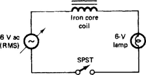
2. Construct the circuit in Fig. 3-1A.

3. Prepare the VOM to measure dc voltage. Close the switch, and measure and record the voltage across the lamp and coil.
V (coil) = _______________ V dc
V (lamp) = ______________ V dc
4. How does the sum of the voltages across the coil and the lamp compare with the source voltage?
___________________________________
Why? _________________________
5. Using the data from steps 1 and 3, compute the current through the coil and lamp:
I = ________________ A.
6. Replace the dc power supply with the ac power source as shown in Fig. 3-1B.
7. Prepare the VOM to measure ac voltage. Close the SPST switch. Measure and record the voltage across the lamp and coil.
V (coil) = _______________ V dc
V (lamp) = ______________ V dc
8. How does the sum of these voltages compare with the source voltage? _________________________
Why? _____________________________________________
9. How does the sum of the voltages in step 4 compare with the sum of the voltages in step 8?
_______________________________________________
Why was this relationship different?
___________________________________________
10. Construct the circuit shown in Fig. 3-1C.
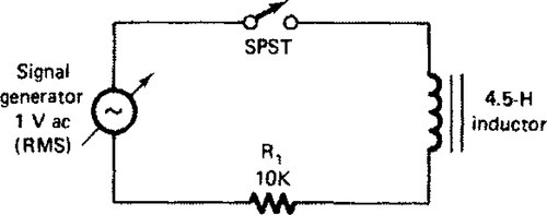
11. Prepare the VOM to measure ac voltage and connect it across R1.
12. Close the switch and complete Fig. 3-1D. Adjust the signal generator to produce the ac frequencies indicated. (Note: The input voltage from the signal generator must be maintained at a constant level for each frequency.)

13. What is the relation between ac frequency and circuit current?
_______________________________________________
14. What is the relation between ac frequency and inductive reactance? ______________________________________
15. What is the relation between inductive reactance and circuit current? ________________________________________
1. What factors determine the inductance of an inductor? ___________________________________________
2. What factors determine the value of inductive reactance? ______________________________________________
3. Why does inductance cause ac current to lag voltage? __________________________________________
4. What is the total inductance when inductors of 4 H and 3 H are connected in series with no mutual inductance factor?
______________________________
5. What is the total inductance when inductors of 4 H and 3 H are connected in parallel with no mutual inductance factor?
_______________________________________________
6. Assume the inductors in Question 4 are connected to aid with a mutual inductance of 0.6 H. What is the total inductance?
____________________________________________________
7. Assume the inductors in question 4 are connected to oppose with a mutual inductance of 0.86 H. What is the total inductance?
_________________________________________________
8. Assume the inductors in question 5 are connected to aid with a mutual inductance of 0.2 H. What is the total inductance?
_______________________________________
9. Assume the inductors in question 5 are connected to oppose with a mutual inductance of 0.9 H. What is the total inductance?
_____________________________________________
10. What is mutual inductance? ________________________________
11. If two inductors valued at 8 H and 10 H are connected in parallel, which allows the most ac current when the ac frequency is 1000 Hz?
_____________________________________________
12. Why will an inductor oppose ac more than dc for any given voltage?
_________________________________________________
Experiment 3-2
Capacitance and Capacitive Reactance
Capacitance is the property of an ac circuit to oppose any increase or decrease in voltage. It is present any time two conductors or plates are separated by a dielectric material. Capacitance is represented by C in mathematical formulas and is measured in farads (F). Components designed to add capacitance to a circuit are known as capacitors and are rated according to their capacitance in farads and their working voltage (maximum dc voltage that can be placed across a capacitor without doing damage to its dielectric). Capacitors, known for their ability to store an electric charge, may be connected in series or parallel.
Capacitance in ac circuit causes current to lead the voltage. The impedance (Z) to ac caused by capacitance is known as capacitive reactance (XC) and is measured in ohms (Ω). Capacitive reactance is computed with the following formula:
where
XC = capacitive reactance in ohms
2π = 6.28
f = frequency in hertz
C = capacitance in farads
Capacitors may be further classified as electrolytic or nonelectrolytic. If electrolytic capacitors are used in a circuit, the polarity printed on the body of the capacitor must be observed.
1. To study capacitance and capacitive reactance.
2. To examine how ac affects capacitive reactance.
3. To make simple computations concerning total capacitance in series and parallel.
VOM (multimeter)
Signal generator
6 V battery
Resistors: 10 kW
Capacitor: 0.01 μF, 100 V dc
Switch
Connecting wires
1. Prepare the VOM to measure resistance of approximately 1000 Ω or its equivalent. Measure and record the resistance of the 0.01 μF capacitor and the 10 kΩ resistor.
Resistor resistance = ___________ Ω
Capacitor resistance = ___________ Ω
2. How do these resistances compare?
_________________________________
3. From the data shown in step 1, which component would allow a dc to flow and which would not?
Would: __________________________
Would not: _________________________
4. Constructthe circuit in Fig. 3-2A.
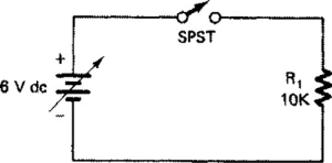
5. Prepare the VOM to measure dc of approximately 10 mA. Connect the VOM to the circuit to measure current. Close the Single Pole Single Throw (SPST) switch and record the current: ___________ mA.
6. Alter the circuit in step 4 to the circuit shown in Fig. 3-2B.
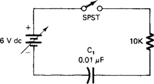
7. Connect the VOM to measure dc (in the 10-mA range). Close the switch and record the current: ________ mA.
8. How did the current recorded in step 5 compare with the current recorded in step 7?
_________________________
9. How do you account for the current difference in steps 5 and 7?
__________________________
10. Alter the circuit in Fig. 3-2B so it is Iike the one in Fig. 3-2C.
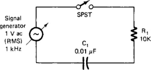
11. Prepare the VOM to measure ac of approximately 10 V.
12. Connect the VOM across R, close the SPST switch, and record the voltage: V across R1 = ______________ V ac.
13. Using the resistance of R1 as measured in step 1 and the voltage measured in step 12, compute the current in this circuit: l = _________ mA.
14. How did the current computed in step 13 compare with the current measured in step 7?
_______________________________
15. Because the two circuits are similar, how do you account for the difference in the currents in steps 7 and 13? _______________________
16. With the YOM connected as in step 12, adjust the signal generator to the frequencies shown in Fig. 3-2D. Complete the figure for each frequency.
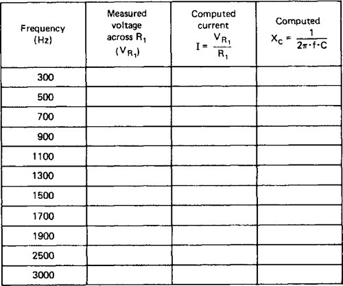
17. From the data recorded in Fig. 3-2D, what is the relation between frequency, current, and capacitive reactance? As frequency increases, the voltage across R1 ___________, current ___________, and XL _________.
1. What is capacitive reactance?
__________________________________
2. What is meant by a capacitor’s working voltage?
__________________________________
3. What variables determine the capacitance of a capacitor?
__________________________________
4. If you connected in series two capacitors valued at 4 μF each what would be the total capacitance?
__________________________________
5. If you connected the two capacitors of question 4 in parallel, what would be their total capacitance?
__________________________________
6. What is the relation between ac frequency and XC? ______________________________________________
7. How does capacitance affect the phase relation between ac and voltage?
__________________________________
8. How does the relation between ac frequency and XC compare with the relation between ac frequency and XL?
__________________________________
Experiment 3-3
Series RL Circuits
Series RL circuits are encountered very often in electronic equipment. When ac voltage is applied to this type of circuit, the current is the same through each component. However, the voltage that drops across each component is distributed according to the relative value of resistance (R) and inductive reactance (XL) in the circuit.
The total opposition to current is called impedance (Z). Resistance and reactance in ac circuits both oppose the current. The impedance of an ac circuit is expressed as follows:
![]()
or for a series RLC circuit:
![]()
To observe the characteristics of a series ac circuit that has resistance and inductance.
AC voltage source
Resistor: 1 kΩ
Inductor: 4.5 H
VOM (multimeter)
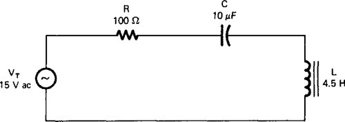
1. Construct the series RL circuit shown in Fig. 3-3A. Apply 15 V ac from an ac power source.
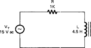
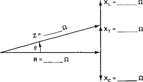
2. Calculate the following values of the circuit:
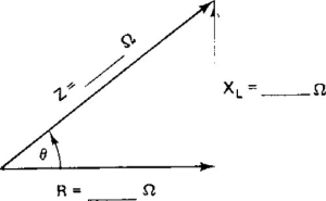
a. Inductive reactance: XL = 2πfL = ______________ Ω
b. Impedance: ![]() ______________
______________
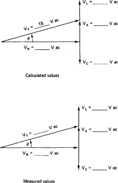
3. With a VOM, measure the following values:
a. Voltage across the resistor:
VR = __________ V ac
b. Voltage across the inductor:
VL = _________ V ac
4. If an ac milliammeter is available, measure the current in the circuit. If not, calculate IT = Vr/R; IT = __________ mA
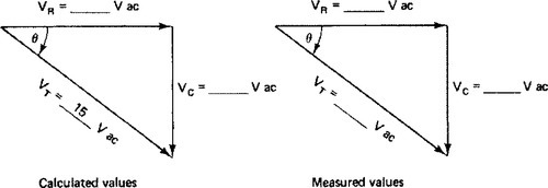
5. Complete the impedance triangle in Fig. 3-3B for the circuit you constructed by using the calculated values of R, XL, and Z. The symbol θ represents the phase angle of the circuit.
6. Calculate the voltage drops in the circuit.
a. Vr = IT× R= _______________ V ac
b. VL = IT × XL = _______________ V ac
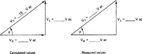
7. Show that the voltages are related in the following way by using the values you calculated and VT = 15 V ac:
8. Complete the voltage triangles for the circuit in Fig. 3-3C using the calculated and then the measured values of VT, VR and VL.
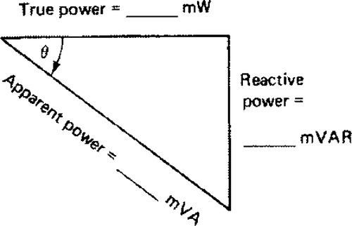
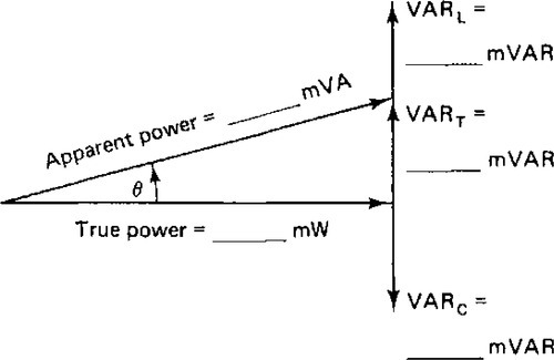
9. Calculate the power converted in the circuit:
a. True power = IT × VR = ___________ mW
b. Apparent power = IT × VT = ___________ mVA
c. Reactive power = IT × VL = ___________ mVAR
10. Complete the power triangle for the circuit in Fig. 3-3D using your calculated values of true power, apparent power, and reactive power.
1. Why must the voltages in a series RL circuit be added by using a right triangle?
________________________________
2. Compare the calculated and measured values of the following:
3. What are some factors that could cause a difference in your measured values and the calculated values? ___________________________________
4. Determine the phase angle of the circuit by using the following trigonometrie methods.
a. Phase angle (θ) = inverse tangent (XL/R) = ___________ °
b. Phase angle (θ) = inverse tangent (VL/VR) = ___________ °
c. Phase angle (θ) = inverse tangent (VAR/W) = _________ °
5. Determine the power factor of the circuit as follows:
6. Determine the cosine of the phase angle (θ). This value should equal the circuit power factor (approximately pf = cosine θ): cosine θ =
______________________________________.
7. What is meant by power factor?
_____________________________________________
Experiment 3-4
Series RC Circuits
Series RC circuits are used in many types of electronic equipment. When ac voltage is applied to this type of circuit, the characteristics are similar to those of a series RL circuit. In a capacitive circuit, current leads voltage and in an inductive circuit voltage leads current. Therefore these reactive values act in the opposite directions. In circuit calculations, the smaller reactance value is subtracted from the larger value to obtain the total reactance (XT) of the circuit.
To study the characteristics of a series ac circuit that has resistance and capacitance.
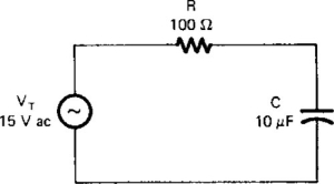
Variable ac voltage source
Resistor: 100 Ω
Capacitor: 10 μF
VOM (multimeter)
1. Construct the series RC circuit shown in Fig. 3-4A. Apply 15 V ac from an ac power source.
2. Calculate the following values of the circuit:
a. Capacitive reactance: 
b. Impedance: Z = R2 + Xc2 = _______ Ω
3. With a VOM, measure the following values:
a. Voltage across the resistor:
VR = ____________ V ac
b. Voltage across the capacitor:
VC = ___________ V ac
4. If an ac milliammeter is available, measure the current in the circuit. If not, calculate the current as IT = Vr/R : IT= _______________ ac mA.
5. Complete the impedance triangle in Fig. 3-4B for the circuit you constructed by using the calculated values of R, XC, and Z.
6. Calculate the voltage drops in the circuit as follows:
a. Vr = IT × R = ______________ Vac
b. VC = IT × XC = ______________ V ac
7. Show that the voltages are related in the following way by using the values you calculated:
![]()
8. Complete the voltage triangles in Fig. 3-4C for this circuit using the calculated then the measured values of VT, VR, and VC.
9. Calculate the power converted in the circuit:
a. True power = IT × VR = _____________ mW
b. Apparent power = IT × VC = __________ mVar
10. Complete the power triangle for the circuit in Fig. 3-4D by using your calculated values of true power, apparent power, and reactive power.

1. Compare the calculated and measured values of the following:
2. Determine the phase angle of the circuit by using the following trigonometrie methods:
a. Phase angle (θ) = inverse tangent (XC/R) = __________ °
b. Phase angle (θ) = inverse tangent (VC/VR) = __________ °
c. Phase angle (θ) = inverse tangent (W/VA) = __________ °
3. Determine the power factor of the circuit as:

4. Determine the cosine of the phase angle. This value should equal the power factor of the circuit: cosine θ = ____________.
Experiment 3-5
Series RLC Circuits
In this experiment you will study the characteristics of an ac circuit that has resistive, capacitive, and inductive components. Because the effects of the capacitance and inductance are 180° out of phase with each other, you must analyze these circuits by using right triangles to show the relations of the values.
To study the characteristics of a series RLC circuit.
AC voltage source
Resistor: 100 Ω.
Capacitor: 10 μF
Inductor: 4.5 H
VOM (multimeter)
1. Construct the series RLC circuit shown in Fig. 3-5A. Apply 15 V ac from an ac power source.
2. Calculate the following:
a. Capacitive reactance:
b. Inductance reactance:
XL = 2πfL ________ Ω
c. Total reactance:
XT = XL – XC = ___________ Ω
d. Impedance:
![]()
3. With a VOM measure the following values:
a. Voltage across the capacitor:
VC = ___________ V ac
b. Voltage across the inductor:
VL = __________ V ac
c. Voltage across the resistor:
VR = ____________ V ac
4. If an ac milliammeter is available, measure the current through the circuit. If not, calculate as IT = VR/R: IT = ___________ mA.
5. Complete the impedance triangle in Fig. 3-5B for the circuit you constructed by using the calculated values of R, XC, XL, and Z.
6. Calculate the voltage drops in the circuit as follows:
a. VR = IT × R = ________ V ac
b. VC = IT × XC = _________ V ac
c. VL = IT × XL = _________ V ac
d. VX = VL – VC = _______________ V ac
7. Show that these voltages are related in the following way by using the values you calculated:
![]()
8. Complete the voltage triangles in Fig. 3-5C for this circuit using the calculated and then the measured values and VT, VR, VL and VC.
9. Calculate the power converted in the circuit:
a. True power: IT × VR = ________ W
b. Apparent power: IT × VT = ________ mVA
c. Capacitive reactive power: VARC = IT × VL = ________ mVAR
d. Inductive reactive power: VARL = IT × VL = ________ mVAR
e. Total reactive power: VART = IT × VX = ________ mVAR
10. Complete the power triangle in Fig. 3-5D for the circuit by using your calculated values of true power, apparent power, and reactive power.
1. Compare the calculated and measured values of the following:
| Value | Calculated | Measured |
| IT | ________ mA | ________ mA |
| VR | ________ V | ________ V |
| VC | ________ V | ________ V |
| VL | ________ V | ________ V |
2. Determine the phase angle of the circuit by using the following trigonometrie methods:
a. Phase angle (θ) = inverse tangent (XT/R) = _________ °
b. Phase angle (θ) = inverse tangent (VX/VR) = ________ °
c. Phase angle (θ) = inverse tangent (VART/W) = _________ °
3. Determine the power factor of the circuit as follows:

4. Determine the cosine of the phase angle. This value should equal the circuit power factor: cosine θ = __________
5. How does the circuit of this experiment show power factor correction (reduction of phase angle by adding capacitance?) ___________
6. As total reactive power increases, the phase angle ____________.
Experiment 3-6
Parallel RL Circuits
Another category of basic ac circuits is the parallel type. Parallel circuits have many applications in electronics. The basic calculations necessary to study parallel ac circuits are somewhat different from those used to study series circuits. Because the impedance (Z) of a parallel circuit is less than individual branch values of resistance, inductive reactance, or capacitive reactance, the impedance relations must be modified. A right-triangle relation exists between the currents in the branches of the circuit.
To study the impedance and current relations of a parallel resistive inductive (RL) circuit with ac applied.
AC voltage source
Resistor: 100 Ω
Inductor: 4.5 H
VOM (multimeter)
1. Construct the parallel RL circuit shown in Fig. 3-6A. Apply 15 V ac from an ac power source.
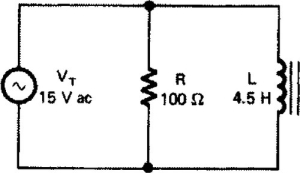
2. Calculate the following:
a. Inductive reactance: XL = 2πfL = ________ Ω
b. Current through the resistor: IR = Vr/R = _______ mA
c. Current through the inductor: IL = VL/XL = _______ mA
d. Total current:
![]()
e. Impedance: Z = VT/IT = _________ Ω
3. Complete the current triangle (Fig. 3-6B) for this circuit using the values from step 2.
4. If an ac milliammeter is available, measure the following values. If not, calculate as follows:
a. Current through the resistor: IR = VT/R = ___________ mA
b. Current through the inductor: IL = VT/XL = _________ mA
c. Total current: IT = VT/Z = _________ mA
5. Because the impedance is less than the individual value of resistance or inductive reactance of the circuit, an admittance diagram must be used. In this diagram, admittance Y = 1/Z, conductance G = 1/R, and inductive susceptance Bl = 1/XL. The unit of measurement is the siemen.
6. Calculate the values necessary to complete the admittance triangle:
a. Admittance: Y = 1/Z = _________ μS
b. Conductance: G = 1/R = _________ μS
c. Inductive susceptance: BL = 1/XL = _______ μS
7. Complete the admittance triangle (Fig. 3-6C) for the circuit.

8. Calculate the power converted in the circuit.
a. True power:
![]()
b. Apparent power:
![]()
c. Reactive power:
![]()
9. Complete the power triangle (Fig. 3-6D) for the circuit.

1. Compare the calculated and measured values of the following:
2. Determine the phase angle of the circuit by the following methods:
a. Phase angle: θ = inverse cosine (IR/IT) = _______ °
b. Phase angle: θ = inverse sine (VARA/A) = _______ °
3. Determine the power factor of this circuit:

4. Compare the power factor value of question 3 with the value of cosine θ from the current triangle of step 3 in the procedure. _______________________
5. Define the following terms associated with parallel ac circuits.
a. Admittance _____________________________
b. Conductance _________________
c. Inductive susceptance _________________________
d. Capacitive susceptance _____________________________
Experiment 3–7
Parallel RC Circuits
In this experiment you will study the characteristics of a parallel RC circuit with ac applied. This type of circuit is similar to the RL circuit; however, the effect of capacitance is opposite that of inductance. Similar triangle relations exist in this circuit.
To study the impedance, current, and power relations of a parallel RC circuit.
Variable ac voltage source
Resistor: 100 Ω
Capacitor: 10 μF
VOM (multimeter)
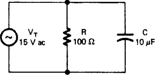
1. Construct the parallel RC circuit shown in Fig. 3-7A. Apply 15 V ac from an ac power source.
2. Calculate the following:

a. Capacitive reactance:
b. Current through the resistor: lR = Vr/R = _________ mA
c. Current through the capacitor: lc = VR/XC_________ mA
d. Total current:
![]()
e. Impedance: Z = VS/IT = ________ Ω
3. Complete the current triangle (Fig. 3-7B) for this circuit using the values from step 2.

4. Measure the following ac current values with an ac milliammeter, if available, or calculate them as shown:
a. Current through the resistor: IR = VT/R _______ mA
b. Current through the capacitor: Ic = VT/XC = _______ mA
c. Total current: IT = VT/Z = ________ mA
5. Calculate the following values:
a. Admittance: Y = 1/Z = __________ μS
b. Conductance: G = 1/R = = __________ μS
c. Capacitive susceptance: (BC) = 1/XC = _________ μS
6. Complete the admittance triangle (Fig. 3-7C) for the circuit.

7. Calculate the power converted in the circuit:
a. True power:
![]()
b. Apparent power:
![]()
c. Reactive power:
![]()
8. Complete the power triangle for the circuit in Fig. 3-7D.
1. Compare the calculated and measured values of the following:
| Value | Calculated | Measured |
| IR | __________ mA | __________ mA |
| IC | __________ mA | __________ mA |
| Ir | __________ mA | __________ mA |
2. Determine the phase angle (θ) of the circuit using the following methods:
a. Phase angle: θ = inverse sine (IC/IR) = _________ °
b. Phase angle: θ = inverse tangent (VAR/W) = _________ °
3. What is the value of the following:
a. Cosine θ = _________ (use correct triangle values)
b.
4. Suppose that a 5 H inductor has been connected in parallel with the circuit of this activity, and compute the following:
a. XL = 2πfL = ___________ Ω.
b. IL = VL/XL = _________ mA
c. IX = IL–IC = _________ mA
d.
![]()
e. Z = VS/IT = _________ Ω
g. θ = inverse sine (IX/IT) = ________ °
g. pf = cosine θ = ________
5. How do the values of power factor for the original circuit and that of question 4 differ?
_____________________________________________________
Why? _________________________________________________
6. How do the values of total current differ in the two circuits? _____________________________________________________
Why? _________________________________________________
Unit 3 Examination
Inductance and Capacitance in AC Circuits
Instructions: For each of the following, circle the answer that most correctly completes the statement.
b. Magnitude
c. Time, direction, and magnitude
d. Magnitude and direction
2. Inductance is the property of an electric circuit that
a. Opposes change in applied voltage
b. Opposes change in current
c. Aids changes in voltage
d. Aids changes in current
3. Capacitance is the property of an electric circuit that
a. Opposes any change in current in the circuit
b. Opposes any change in voltage in the circuit
c. Is not affected by a change in voltage
d. Aids any change of current in the circuit
4. The unit of measurement of reactive power is:
b. Volt-ampere-wattage (VAW)
c. Volt-ampere-kilowatt (VAkW)
d. Volt-ampere-reactive (VAR)
5. The prime factors that determine inductive reactance are:
b. Frequency and induced voltage
c. Frequency and inductance
d. Inductance and current
6. Assume that the component values in a series RCL circuit are R = 4 Ω, XC = 3 Ω, and XL = 6 Ω. The total reactance in the circuit is approximately
b. 8 Ω
c. 8 Ω
d. 9 Ω
7. Assume that a series circuit contains both inductance and resistance. The phase angle between the applied voltage (EA) and the resistive voltage drop (ER) is the same as the phase angle between
b. Resistance and impedance
c. Reactance and resistance
d. Resistance and susceptance
8. When frequency is increased in a series RL circuit, the a. current flow will
a. Increase because of greater XL
b. Increase because of less XL
c. Decrease because of greater XL
d. Decrease because of less XL
9. Voltage and current are considered to be out of phase with each other in a purely inductive circuit by what amount?
a. Current leads voltage by 90°
b. Current lags voltage by 90°
c. Current leads voltage by 180°
d. Current lags voltage by 180°
10. The phase angle between current and voltage in a circuit containing both resistive and inductive elements is:
a. Greater than 0° but less than 90°
b. A constant 45°
c. 90° at all times
d. 0° because XL and R are equal
11. What is impedance?
a. Opposition to the current flow in an ac circuit created by resistance and reactance
b. Resistance of an ac circuit
c. Vector sum of voltage drops in an ac circuit
d. Current divided by voltage in an ac circuit
12. In a circuit containing both XC and XL, if the difference between XC and XL increases
b. Total impedance increases
c. Total impedance remains the same
d. Resistance increases
13. The hypotenuse of the power triangle represents
b. Apparent power
c. VAR
d. None of the above
14. The inductance of a coil is measured in which unit?
b. Farads
c. Henrys
d. Volts
15. Inductive reactance in an ac circuit increases with
b. A decrease in resistance
c. An increase in resistance
d. A decrease in frequency
16. When the impedance of an ac circuit is greater than the dc resistance because of the presence of an inductor, the cause is
b. XR (resistive reactance)
c. XL (inductive reactance)
d. XM (mutual reactance)
17. In an ac circuit that contains an inductive device, the current
a. Is in phase with the voltage
b. Lags the voltage
c. Leads the voltage
d. Is 180° out of phase with the voltage
18. In an ac circuit that contains a capacitive device, the current
b. Lags the voltage
c. Leads the voltage
d. Is 180° out of phase with the voltage
19. Increasing the frequency of the applied ac in a capacitive circuit will cause capacitive reactance to
b. Decrease
c. Remain constant
d. Be increased to a resonant state
20. The capacitance of a capacitor is measured in
b. Henrys
c. Ohms
d. Mhos
21. Measured electric power expressed in watts is referred to as
b. True power
c. Unity power
d. Power factor
22. The waveforms in Fig. E-22 represent a power factor of
b. Cannot be determined
c. 1.0
d. 0.5
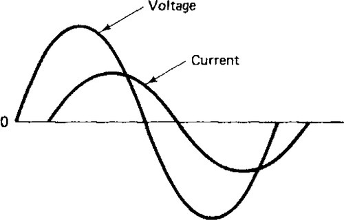
Fig. E-22
23. The waveforms in Fig. E-22 are typical of a:
b. Inductive circuit
c. Resistive circuit
d. Combination
24. The waveform in Fig. E-23 illustrates
b. A capacitive circuit
c. An inductive circuit
d. Two-phase ac

Fig. E-23
25. What is the impedance of the circuit of Fig. E-24?
b. 50 Ω
c. 11 Ω
d. 5 Ω
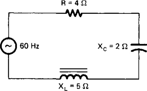
Fig. E-24