Electronic Instruments
Electronic instruments of many types are in use today. They measure many different quantities. Instruments are used to measure electric quantities and other physical quantities. In unit 2, you learned to use a multimeter (VOM) to measure voltage, current, and resistance. These are basic electric quantities.
All instruments have common characteristics. A quantity is monitored either periodically or continuously. A visual display of the quantity must be presented. Several types of instruments are used for measuring electric quantities. The basic types of instruments may be classified as (1) analog instruments, (2) comparison instruments, (3) cathode-ray tube (CRT) instruments, (4) numerical readout instruments, and (5) chart-recording instruments.
Important Terms
Review the following terms before studying electronic instruments in this unit.
Ammeter A meter used to measure current flow.
Bridge circuit A circuit with groups of components that are connected by a bridge in the center and used for precision measurements.
Cathode-ray tube (CRT) A large vacuum tube in which electrons emitted from a cathode are formed into a narrow beam and accelerated and on striking a phosphorescent screen produce a visible pattern of light energy.
d’Arsonval meter movement The internal portion of an analog meter, which has a stationary permanent magnet, an electromagnetic coil, and a pointer that moves in direct proportion to the current flow through the coil.
Galvanometer A meter used to measure very small current values.
Loading The effect caused when a meter is connected into a circuit that causes the meter to draw current from the circuit.
Megohmmeter A meter used to measure very high resistances; also called a megger.
Moving coil See d’Arsonval meter movement.
Multiplier A resistance connected in series with a meter movement to extend the range of voltage measured.
Ohmmeter A meter used to measure resistance.
Ohms per volt rating (Ω/V) The rating that indicates the loading effect of a meter on a circuit when making a measurement.
Oscilloscope An instrument that has a cathode-ray tube to allow visual display of voltages.
Sensitivity See ohms per volt rating.
Shunt A resistance connected in parallel with a meter movement to extend the range of current measured.
Voltmeter A meter used to measure voltage.
Watt-hour A unit of energy measurement equal to 1 watt per hour.
Watt-hour meter A meter used to measure the rate of power conversion.
Wattmeter A meter used to measure power conversion.
Wheatstone bridge A bridge circuit used to make precision resistance measurements by means of comparing an unknown resistance with a known or standard resistance value.
X axis A horizontal line on a standard graph.
Y axis A vertical line on a standard graph.
Analog Instruments
Instruments that rely on the motion of a hand or pointer are called analog instruments. A volt-ohm-milliammeter (VOM), an instrument used for measuring several electric quantities, is one type of hand-deflection instrument. Single-function meters also are used to measure electric quantities. They measure only one quantity.
The basic part of an analog meter is called a meter movement. Physical quantities such as airflow or fluid pressure can be measured with analog meters. The movement of the hand or pointer over a calibrated scale indicates the quantity being measured.
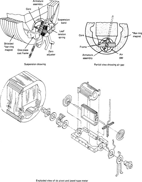
Many analog meters use the d’Arsonval, or moving-coil, type of meter movement. The construction details of this meter movement are shown in Fig. 5-1. The hand or pointer of the movement stays on the left side of the calibrated scale. A moving coil is located inside a horseshoe magnet. Current flows through the coil from the circuit being tested. A reaction occurs between the electromagnetic field and the horseshoe magnet. This reaction causes the hand to move toward the right side of the scale. This moving-coil meter movement operates on the same principle as an electric motor. It can be used for single-function meters that measure only one quantity. It can also be used for multifunction meters, such as VOMs or digital voltmeters (DVMs), which are used to measure more than one quantity. D’Arsonval meter movements can be used to measure voltage, current, or resistance. Resistors of proper value are connected internally to the meter movement for making these measurements.
Measuring Direct Current
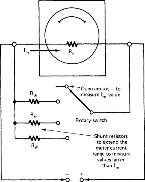
The moving-coil meter movement can be used to measure any value of direct current by use of shunt resistors in parallel with the movement. A diagram of a basic movement with a shunt resistor is shown in Fig. 5-2. The coil of the meter movement will not handle high currents. The typical current rating of a meter movement ranges from 10 μA to 10 mA. This current rating (IM) is the amount of current needed to move the pointer to the extreme right side of the scale. This is called full scale. When this current value is smaller, more turns of wire are used for the coil. More turns allow a strong electromagnetic field to develop. As the current rating (IM) decreases, the resistance (RM) of the movement increases because of the greater length of wire. You must know the values of IM and RM to design a meter circuit that will measure currents higher than the value of IM.
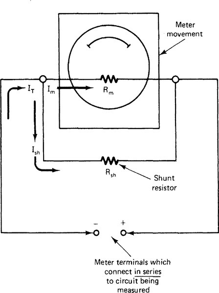
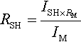
A shunt resistor is placed in parallel with the meter movement, as shown in Fig. 5-2. Some of the current flowing through the external circuit is “shunted” through the resistor. For this reason the resistor is called a shunt resistor (RSH). The value of shunt resistance must be precisely calculated. Shunt resistance produces conditions that allow measurement of ranges of current above the value of the meter movement. The value of shunt resistance is found with the following formula:

where RSH is the shunt resistance in ohms, IM is the full-scale current of rating of the meter movement in amperes, RM is the resistance of the meter movement in ohms, and ISH is the current flow through the shunt resistor in amperes.
For example, a 1.0 mA, 100 Ω meter movement can be used to measure 10 mA. The shunt resistance value is found as follows:
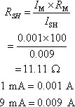
The value of ISH is 9 mA (0.009 A), or 10 mA – 1 mA = 9 mA. This amount of current must be shunted through the shunt resistor. At the maximum current of the 10 mA range, IM equals 1.0 mA. A multirange ammeter is designed with several values of shunt resistance and a switching arrangement, as shown in Fig. 5-3. Multirange meters usually have only one scale. They are read directly or have a multiplying factor so that the scale may easily be read for each range. Scales are discussed in unit 2. This type of scale is called a linear scale. It has the same distance between all division marks.
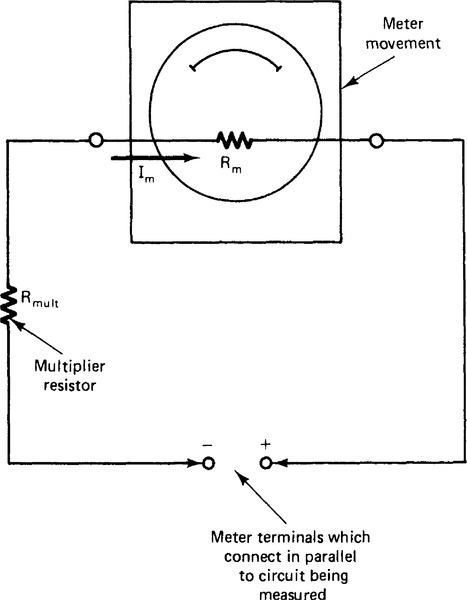
Measuring DC Voltage
Hand-deflection meter movements are another way to measure dc voltage. Meter movements respond to current flow through the electromagnetic coil. As voltage increases, current increases in the same proportion. Voltage values also produce accurate readings on a calibrated meter scale. To measure voltage, a resistor is placed in series with the meter movement. This resistor, shown in Fig. 5-4, is called a multiplier resistor. The purpose of the multiplier is to adjust the value of current across the meter movement. At a certain voltage value (IM × RM), full-scale deflection (VFS) on the meter scale occurs. The formula to find full-scale deflection is as follows:
![]()
A range of dc voltage from 0 to 10 V can be measured with 1.0 mA, 100 Ω meter movement. With 1.0 mA flowing through the 100 Ω meter movement (full scale), 0.1 V is applied across the meter movement (VFS = 1 mA × 100 Ω = 0.1 V). To measure 10 V at full scale, a multiplier resistance is added in series with the meter movement to drop 9.9 V. This value is found with the following formula:
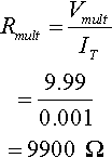
Another way to find the value of a multiplier resistance is to calculate the total resistance in the circuit. The values for the circuit with 10 V applied are found as follows:

The total resistance of the circuit is RT = RM + Rmult so

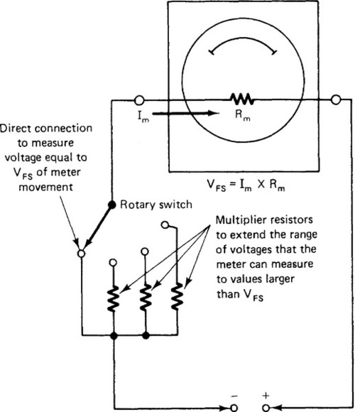
A switching arrangement is used for several voltage ranges that use the same meter movement. A switching arrangement for a multirange voltmeter is shown in Fig. 5-5.
An important characteristic of meters is sensitivity. The sensitivity of a meter increases as the current rating (IM) decreases. Voltmeters are connected in parallel with a circuit to measure voltage. Part of the circuit current flows through the meter to make the needle deflect. The current that flows through the meter should be very small. More sensitive meters draw less current from the circuit. Sensitivity is measured in ohms per volt and is equal to 1/IM. Remember that IM is the current required for full-scale deflection of the meter. A 1 mA movement would have an ohms per volt rating of 1/0.001, or 1000 Ω/V. This means that the meter would have 1000 Ω of resistance for its 1 V range. Sensitivities of meter movements range from as low as 100 Ω/V to as high as 200,000 ΩV. Low-sensitivity meters should not be used for making accurate measurements.
Measuring Resistance
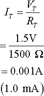
Resistance can be measured with a meter movement. An ohm-meter circuit is shown in Fig. 5-6a.The resistance to be measured is connected in series with the meter circuit. A 1.5 V cell is used to supply current to the meter circuit. The scale of the meter is calibrated so that the movement of the pointer indicates a value of resistance. When the meter probes are touched together, the meter pointer is adjusted to full scale. An ohms scale is shown in Fig. 5-7a. The full-scale mark (right side) indicates zero resistance. As higher values of resistance are measured, less current flows through the meter circuit. The ohmmeter pointer deflects less for higher resistance values. The ohms-adjust control is a potentiometer used to adjust the meter pointer. An ohmmeter must be zeroed before measurements are made. The pointer is adjusted to the zero on the scale when the probes are touched together. The purpose of the ohms-adjust control is to allow accurate measurements as the voltage of the battery in the circuit changes. The left side of the scale indicates infinite resistance. This is an open circuit that has no current flow.


In the ohmmeter circuit of Fig. 5-6a a 1.0 mA, 100 Ω meter movement is used. A value of 900 Ω for the current-limiting resistor (Rlim) is calculated in Fig. 5-7b. The total resistance of the meter circuit will be + RM + Rlim + Rohms, or 100 Ω + 900 Ω + 500 Ω = 1500 Ω. When the meter probes are touched together, the total current in the circuit will be 1 mA:
One milliampere is the current (IM) for full-scale deflection of the meter. The ohms scale is calibrated to read 0 Ω at the full-scale deflection point of the meter.
The measured resistance that causes half-scale deflection of the meter pointer is equal to the total resistance of the ohmmeter circuit. To measure a 1500 Ω resistance, the resistor is connected between the meter probes. The total circuit resistance is then 3000 Ω. The meter pointer deflects to only one-half of full scale. With twice as much resistance in the circuit, there is only half as much current. The center of the ohms scale is marked 1500 Ω, as shown in Fig. 5-7b.
If the 3000 Ω resistance is measured, the total circuit resistance is 4500 Ω. This is three times the resistance of the meter circuit. The current in the circuit is then only one-third of the full-scale current (.33 mA). The meter pointer deflects to only one-third of full scale when 3000 Ω is measured. The point on the ohms scale for 3000 Ω is marked. The amount of current can be calculated for any value of measured resistance. The ohms scale is marked according to the current value. The table in Fig. 5-7b shows some values used to calibrate the ohms scale of a meter. This type of scale is called a nonlinear scale. It has division marks that are farther apart on the right than on the left.
There are limits to the amount of resistance an ohmmeter can measure. Several values can be measured with a multirange ohmmeter that has a small battery (usually 1.5 V) for the × 1 and × 100 ranges and a larger battery (usually 9 or 30 V) for ranges of × 1000 and higher.
Multifunction meters (multimeters) usually are designed to measure voltage, current, and resistance. Most hand-deflection analog meters have one meter movement with internal circuits to make many types of measurements. A rotary switch often is used for multimeters to select the quantity to be measured and the proper range.
Self-Examination
1. The five basic types of instruments are _____, _____, _____, _____, _____.
2. A _____ meter measures one quantity.
3. The range of a meter movement is extended to measure higher current values by means of addition of a _____.
4. The following abbreviations are: (a) IM _____, (b) RM _____, (c) RSH _____, and (d) ISH _____.
5. A meter movement is used to measure higher voltages by adding a _____.
6. Explain the following abbreviations, (a) VFS _____, (b) Rmult _____
Solve the following ammeter circuit-design problems.
7. Using a meter movement with resistance (RM) of 300 Ω and current (IM) of 400 μA, calculate the value of shunt resistance (RSH) needed to extend its range to measure 200 mA of current. RSH = _____
8. If a 200 Ω, 1 mA meter movement is used, what values of shunt resistance are needed to extend its range to measure the following currents?
b. 10 mA _____
c. 50 mA _____
d. 100 mA _____
e. 9.5 mA _____
f. 1 A _____
g. 2A _____
h. 400 μA _____
Solve the following voltmeter circuit-design problems.
9. Find the voltage for full-scale deflection (VFS) of a meter movement with RM = 400 Ω and IM = 0.5 mA. VFS = _____
10. Find the voltage (Vmult) that must be dropped across the multiplier resistor to measure 10 V for the meter movement used in problem 9. Vmult = _____
11. Find the value of multiplier resistor (Rmult) needed in series with the meter movement of problem 9 to measure 10 V. Rmult = _____
12. Calculate the values of multiplier resistance needed to extend the range of a 1 mA, 100 Ω meter movement to measure the following voltages.
b. 5 V, Rmult = _____ Ω
c. 15 V, Rmult = _____ Ω.
d. 150 V, Rmult = _____ Ω
e. 300 V, Rmult = _____ Ω
f. 500 V, Rmult = _____ Ω
g. 1000 V, Rmult = _____ Ω
Solve the following ohmmeter circuit-design problems.
13. Use a meter movement with Rm = 500 Ω, Im = 0.5 mA, and a 1.5 V battery. Find the total resistance needed in the ohmmeter circuit when using a 1.5 V battery. RT = _____
14. Find the value of a limiting resistor (Rlim) needed for the circuit in problem 13. Rlim = _____
15. Draw a half-circle on a sheet of paper to represent an ohmmeter scale and mark the following points on the scale. Use the circuit values of problems 13 and 14.
a. Full scale on the right side (0 Ω)
b. Infinite on the left side (∞ Ω)
c. Half-scale (Rlim + RM value) _____ Ω
d. One-fourth scale = _____ Ω
e. Three-fourths scale = _____ Ω
16. Find the value of Rlim needed for a 1 mA, 100 Ω meter movement using a 9 V battery. Rlim = _____
17. Using the circuit values of problem 16, calculate the values of resistance for the following deflections on an ohmmeter scale:
b. One-half scale = _____ Ω
c. Three-fourths scale = _____ Ω
Answers
1. Analog, comparison, CRT, numerical readout, chart recording
2. Single-function
3. Shunt resistance (RSH)
4.
(b) meter resistance;
(c) shunt resistance;
(d) shunt current
5. Multiplier resistance
6.
(b) multiplier resistance
7. RSH = 0.6012 V
8.
b. 22.22 Ω
c. 4.082 Ω
d. 2.0202 Ω
e. 23.53 Ω
f. 0.2002 Ω
g. 0.10005 Ω
h. No RSH
9. VFS = 0.2 V
10. Vmult = 9.8 V
11. Rmult = 19,600 Ω
12.
b. 4900 Ω
c. 14,900 Ω
d. 149,000 Ω
e. 299,900 Ω
f. 499,000 Ω
g. 999,900 Ω
13. 3000 Ω
14. 2500 Ω
15.
b. ∞
c. 3 kΩ
d. 9 kΩ
e. 1 kΩ
16. 8800 Ω
17.
b. 9000 Ω
c. 3000 Ω
Measuring Electric Power
Electric power is measured with a wattmeter. A meter movement called a dynamometer is used for most wattmeters. Figure 5-8 shows a meter movement that has two electromagnetic coils. One coil, called the current coil, is connected in series with the circuit to be measured. The other coil, called the potential coil, is connected in parallel with the circuit. The strength of each electromagnetic field affects the movement of the meter pointer. The operating principle of this movement is like that of the moving-coil type. The main difference is that an electromagnetic field rather than a permanent magnet field surrounds the moving coil. DC power is found by means of multiplying voltage and current (P = V × I). AC power is found by means of multiplying voltage, current, and the power factor (pf) of the load (P = V × I × pf). The true power of an ac circuit is read with a wattmeter. When a load is either inductive or capacitive, the true power is less than apparent power (V × I). The true power is the actual power converted by the load.

Measuring Electric Energy
Wattmeters with dynamometer movements are used to measure electric power. They monitor the voltage and current in a circuit. They are used to measure the electric power converted by a load. The amount of electric energy converted into mechanical energy by a motor load is measured by means of connecting a wattmeter to the motor circuit.
The amount of electric energy used over a period of time is measured with a watt-hour meter. A watt-hour meter normally has a small motor inside. The speed of the motor increases as more current passes through it. The rotor is an aluminum disk and is connected to a numerical display. The display indicates the number of kilowatt-hours of electric energy used. Other types have a numerical display of actual kilowatt-hours used.
Watt-hour meters are connected between the power lines coming into a building and the branch circuits inside the building. The electric energy used by a building must pass through the kilowatt-hour meter. The operation of a watt-hour meter is similar to that of a wattmeter. A voltage coil is connected in parallel with power lines to monitor voltage. A current is placed in series with one line to measure current. The voltage and current of the system affect the speed of the aluminum disk. A watt-hour meter is similar to an ac induction motor. This stator is an electromagnet that has two sets of windings: the voltage windings and the current windings. The field developed in the voltage windings causes current to be induced into the aluminum disk. The speed of the disk increases when the voltage or current of the system increases. Because voltage usually stays the same, the speed of the disk increases as current increases. This causes the number display to increase. Watt-hour meters are used to monitor the true power converted in a system over a period of time.
Measuring Three-phase Electric Power
It often is necessary to monitor the three-phase power used by industrial and commercial buildings. A combination of single-phase wattmeters can be used to measure three-phase power, as shown in Fig. 5-9. The method shown is not practical. The sum of the meter readings is used to determine the total power of a three-phase power system. A meter called a three-phase wattmeter is used to measure the true power of a three-phase system. The power indicated on the meter depends on the voltage and current of all three phases of the system. Three-phase watt-hour meters are available. They contain three aluminum disks to monitor the three-phase power used by a system over a period of time. The rotation of the shaft is caused by a combination of the power of each phase. The kilowatt-hour display increases as the three-phase power converted by the system increases.

Measuring Power Factor
Power factor is the ratio of the measured true power of a system to the apparent power (volts × amperes). A wattmeter, a voltmeter, and an ammeter may be used to find the power factor of a system. The power factor can be found as pf = W/VA. It is more convenient to use a power factor meter when power factor must be measured.
The circuit of a power meter is shown in Fig. 5-10. A power factor meter is similar to a wattmeter. It has two armature coils that rotate because of their electromagnetic field strengths. The armature coils are mounted on the same shaft. They are placed about 90° apart. One coil is connected across the power line in series with a resistance (R). The other coil is connected across the line in series with an inductance (L). The resistor in series with the coil produces a magnetic field from the in-phase part of the power. The inductor in series with the other coil produces a magnetic field caused by the out-of-phase part of the power. The scale of the meter is calibrated to measure power factors of 0 to 1.0, or 0 to 100%.

Measuring Power Demand
A power-demand meter is an important instrument for industries and large commercial buildings. Power demand is found with the following formula:

Power demand is important because it shows the ratio of average power used to the peak value that a utility company must supply. Power demand usually is calculated over 15-, 30-, or 60-min intervals. It may be converted into longer periods of time.
The utility company may penalize industries and businesses if their peak power demand is far greater than their average demand. This is called a demand charge. Power-demand meters help companies use their electric power more effectively. High peak demand means the equipment used for power distribution must be larger. The closer the peak demand is to the average demand, the more efficient is the power system.
Measuring Frequency
Another important measurement is frequency. The frequency of the power system must remain the same at all times. Frequency refers to the number of cycles of voltage or current that occur in a given period of time. The international unit used to measure frequency is the hertz (Hz). One hertz equals one cycle per second. A table of frequencies is shown in Table 5-1. The standard power frequency in the United States is 60 Hz. Some countries use 50 Hz.
Table 5-1
Frequency Values*
| Band | Frequency Range |
| Extremely low frequency | 30 Hz–300 Hz |
| Voice frequency | 300 Hz–3 kHz |
| Very low frequency | 3 kHz–30 kHz |
| Low frequency | 30 kHz–300 kHz |
| Medium frequency | 300 kHz–3 MHz |
| High frequency | 3 MHz–30 MHz |
| Very high frequency | 30 MHz–300 MHz |
| Ultrahigh frequency | 300 MHz–3 GHz |
| Super-high frequency | 3 GHz–30 GHz |
| Extremely high frequency | 30 GHz–300 GHz |
* Power frequency = 60 Hz; AM radio band = 550–1600 kHz; FM radio band = 88–108 MHz.
Frequency is measured with several different types of meters. An electronic counter is used to measure frequency. Vibrating-reed frequency meters often are used. An oscilloscope also is used to measure frequency. Graphic recording instruments can be used to give a visual display of frequency over a period of time. The power industry, for example, must monitor the frequency of its alternators at all times.
Ground-Fault Indicators
A ground-fault indicator is used to locate faulty grounding of equipment or power systems. Equipment must be properly grounded. A ground-fault indicator is used to check for faulty grounding. Several grounding conditions exist that might be dangerous. Faulty conditions include (1) hot and neutral wires reversed, (2) open equipment-ground wires, (3) open neutral wires, (4) open hot wires, (5) hot and equipment grounds reversed, and (6) hot wires on neutral terminals. Each of these conditions presents a serious problem. Proper wiring eliminates most of these problems. A check with a ground-fault indicator assures safe and efficient electric wiring in a building.
Measuring High Resistance
A megohmmeter is used to measure very high resistances. These resistances are beyond the range of most ohmmeters. Megohmmeters are used to check the quality of insulation on electric equipment in industry. The quality of insulation of equipment varies with age, moisture content, and applied voltage. Megohmmeters are similar to most ohmmeters. They have hand-crank, permanent-magnet dc generators rather than batteries as voltage sources. The operator cranks the dc generator while making a test. Insulation tests should be performed on all power equipment. Insulation breakdown causes equipment to fail. Insulation resistance value can be used to determine when equipment has to be replaced or repaired. A decrease in insulation resistance over time means that a problem might soon exist.
Clamp-on Meters
Clamp-on meters are used to measure current in power lines. They are used to check current by means of clamping around a power line. They are easy to use for maintenance and testing of equipment. The meter is simply clamped around a conductor. Current flow through a conductor produces a magnetic field around the conductor. The magnetic field induces a current into the iron core of the clamp-on part of the meter. The meter scale is calibrated to indicate current flow. An increase in current flow through a power line causes the current induced into the clamp-on part of the meter to increase. Clamp-on meters usually have voltage and resistance ranges to make them more versatile.
Comparison Instruments
Another type of indicator is called a comparison instrument. A comparison instrument is used to compare a known value with an unknown value. The accuracy of a comparison instrument is much greater than that of hand-deflection instruments. Comparison instruments can be used to make very accurate measurements.
Wheatstone Bridge
A Wheatstone bridge is a comparison instrument. The circuit of a Wheatstone bridge is shown in Fig. 5-11. A voltage source is used with a sensitive zero-centered movement and a circuit called a resistance bridge. The resistance circuit has an unknown external resistance (Rx), which is the resistance to be measured. Resistor Rs is the known “standard” resistance. Rs is adjusted so that the current path of Rx and Rs is the same value as the path formed by R1 and R2. No current flows through the meter at this time. The meter indicates zero current. This is called a null condition. The bridge is said to be balanced. The value of Rs is marked on the instrument to compare with the value of Rx. Resistors R1 and R2 are called the ratio arm of the bridge circuit. The value of the unknown resistance (Rx) is found with the following formula:

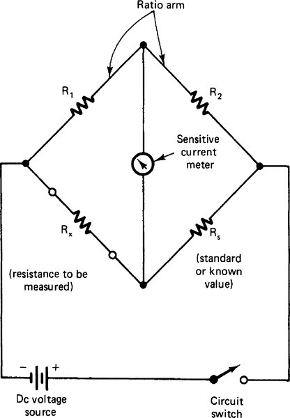
Wheatstone bridges are used to measure resistance with precision. Other comparison instruments are based on the Wheatstone bridge principle. Comparison instruments are used to compare unknown quantities with known quantities in the circuits of the instruments.
CRT Instruments
CRT instruments usually are called oscilloscopes. Oscilloscopes are used to monitor voltages of a circuit visually. The basic part of the oscilloscope is a cathode-ray tube (CRT).
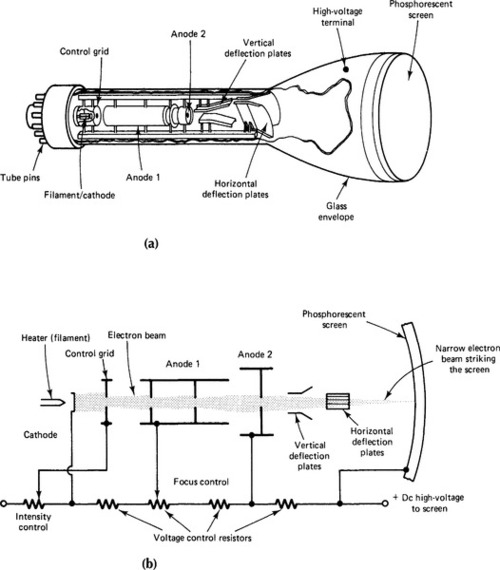
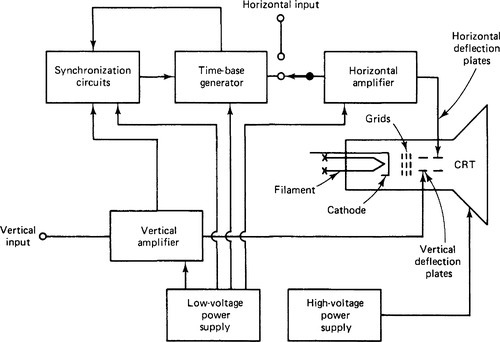
Figure 5-12 shows the construction of a CRT and its internal electron gun assembly. A beam of electrons is produced by the cathode of the tube. Electrons are given off when the filament is heated by a filament voltage. The electrons have a negative (–) charge. They are attracted to the positive (+) potential of anode 1. The number of electrons that pass to anode 1 is changed by the amount of negative (–) voltage applied to the control grid. Anode 2 has a higher positive voltage applied. The higher voltage accelerates the electron beam toward the screen of the CRT. The difference in voltage between anodes 1 and 2 sets the point where the beam strikes the CRT screen. The screen has a phosphorescent coating, which produces light when electrons strike the CRT. The horizontal and vertical movement of the electron beam is controlled with deflection plates. With no voltage applied to either set of plates, the electron beam appears as a dot in the center of the CRT screen. The movement of the electron beam caused by the change of plates is called electrostatic deflection. When a potential is placed on the horizontal and vertical deflection plates, the electron beam moves. Horizontal deflection is produced by a circuit inside the oscilloscope called a sweep oscillator circuit. A voltage “sweeps” the electron beam back and forth across the CRT screen. The horizontal setting of an oscilloscope is adjusted to match the frequency of the voltage being measured. Vertical deflection is caused by the voltage being measured. The voltage to be measured is applied to the vertical deflection of the oscilloscope. A block diagram of an oscilloscope circuit is shown in Fig. 5-13. Oscilloscopes are used to measure ac and dc voltages, frequency, phase relations, distortion in amplifiers, and various timing and special-purpose applications. They also have important medical uses, such as to monitor heartbeat.
Numerical Readout Instruments
Many instruments have numerical readouts to simplify measurement. They make very accurate measurements. Instruments such as digital counters and digital multimeters are commonly used. Numerical readout instruments have internal circuits that produce a digital display of the quantity being measured. These instruments are easy to read because a scale does not have to be interpreted.
Chart-Recording Instruments
Most instruments are used in applications in which no permanent record of the measured quantity is needed. Sometimes instruments must provide a permanent record of a quantity over a period of time. Some chart recorders have pen-and-ink recorders; others have inkless recorders.
A pen-and-ink recorder has a pen that touches a paper chart. The ink leaves a permanent record of the measured quantity on the chart. The chart is either a roll chart, which revolves on rollers under the pen mechanism, or a circular chart, which rotates under the pen. A chart recorder sometimes has more than one pen to record several different quantities at the same time.
The pen of a chart recorder is connected to the meter movement. The pen is supplied with a source of ink. It is moved by the meter movement in the same way as the pointer of a hand-deflection meter. The charts usually have lines that indicate the amount of pen movement. Spaces on the chart are marked according to time periods. Charts are moved under the pen at a constant speed. Spring-drive mechanisms, synchronous ac motors, or dc servomotors are used to drive charts.
Inkless recorders may have voltage applied to the pen point. Heat is produced, which causes a mark to be made on a sensitive paper chart. The advantage of inkless recorders is that ink is not needed. The ink in pen-and-ink recorders must be replaced, and it is often messy to use.
A special type of chart-recording instrument is the X-Y recorder. X-Y recorders are used to plot the relation of two quantities. A variable quantity often is plotted in relation to time. One variable quantity can be plotted in relation to another variable quantity. One input is applied to cause vertical (Y axis) movement of the indicating pen. The other input causes horizontal (X axis) movement of the pen. The plot produced on the chart shows the relation of two quantities connected to the X and Y inputs.
Self-Examination
18. Electric power is measured with a _____.
19. Wattmeters with _____ movements are used to measure electric power.
20. The amount of electric energy used over a period of time is measured with a _____ meter.
21. The ratio of true power to apparent power is called _____.
22. The ratio of peak power to average power is _____.
23. A vibrating-reed meter may be used to measure _____.
24. Very high resistances may be measured with a _____.
Solve the following Wheatstone bridge problems.
25. Calculate the values of Rx using R1 = 1 kΩ and R2 = 10 kΩ for the following values of Rs:
b. Rs = 500 Ω, Rx = _____ Ω
c. Rs = 10.2 kΩ, Rx = _____ Ω
d. Rs = 5.6 kΩ, Rx = _____ Ω
e. Rs = 100 kΩ, Rx = _____ Ω
f. Rs = 22 kΩ, Rx = _____ Ω
Answers
19. Dynamometer
20. Watt-hour
21. Power factor
22. Power demand
23. Frequency
24. Megohmmeter
25.
b. 50 Ω.
c. 1020 Ω
d. 560 Ω
e. 10,000 Ω
f. 22,000 Ω
Unit 5 Examination
Electronic Instruments
Instructions: For each of the following, circle the answer that most correctly completes the statement.
1. The type of electric power that is measured in watts is
b. True power
c. Unity power
d. Power factor
2. The most often used analog meter movement is the
b. d’Arsonval Type
c. Repulsion vane type
d. Solenoid type
3. A device that allows current to flow in only one direction is a
b. Carbon resistor
c. Diode
d. Capacitor
4. A meter that measures voltage, current, and resistance is
b. A multirange meter
c. A current meter
d. A multimeter meter
5. The d’Arsonval meter movement rotates as a result of
a. Mechanical force exerted upon it
b. Heat energy buildup within the meter
c. Production of light by cells within the meter
d. Electric current flowing through it
6. A typical value of current that could pass through a meter movement is
b. 1 mA
c. 10 A
d. μA
7. When a wattmeter is connected into a circuit, it is placed
a. In parallel with the circuit
b. In series with the circuit
c. So that one section of the meter is in series and the other is in parallel with the circuit
d. So that an excess amount of current will not flow through the circuit under measurement
8. The range of the meter movement of a voltmeter may be extended with
a. A multiplier resistor in parallel with the movement
b. A shunt resistor
c. A multiplier in series with the movement
d. A parallel potentiometer
9. A meter movement can be used to measure larger values of current by means of
a. Adding resistors in series with the movement
b. Adding resistors in parallel with the movement
c. Using a multiplier
d. Using overload relays
10. The calculation of a shunt for a meter movement is a good example of the application of
b. Thevinin’s theorem
c. Norton’s theorem
d. The superposition theorem
11. To calculate the value of RSH in a meter shunt circuit, which equation should be used?
b. ![]()
c. ![]()
d. ![]()
12. The “loading” effect of a meter is less evident when a meter is used where the ohms-per-volt rating is
b. 1000 Ω/V
c. 0 Ω/V
d. 10,000 Ω/V
True-False: Place either T or F in each blank.
| _____ 13. | Electric power is measured with a dynamometer meter movement. |
| _____ 14. | Watt-hour meters are used to monitor electric energy used in homes. |
| _____ 15. | The measurement of power factor provides a ratio of true power and apparent power in a system. |
| _____ 16. | Power demand is measured as a ratio of peak power and potential power used by a system. |
| _____ 17. | Frequency may be measured with aVOM. |
| _____ 18. | Clamp-on meters are versatile instruments that may be used to measure current in power lines. |
| _____ 19. | Low values of resistance are typically measured with a megohmmeter. |
| _____ 20. | A Wheatstone bridge is a type of comparison instrument. |