Measuring Voltage, Current, and Resistance
Another important activity in the study of electronics is measurement. Measurements are made in many types of electronic circuits. The proper ways of measuring resistance, voltage, and current should be learned. These are the three most common electric measurements.
Important Terms
Before reading this unit, review the following terms for a basic understanding of terms associated with electronic measurement.
Ammeter A meter used to measure current (amperes).
Continuity check A test to see whether a circuit is an open or closed path.
Multimeter A meter used to measure two or more electric quantities, such as a volt-ohm-milliammeter (VOM), which measures voltage, resistance, and current, or a digital voltmeter (DVM).
Multirange meter A meter that has two or more ranges to measure an electric quantity.
Ohmmeter A meter used to measure resistance (ohms).
Polarity The direction of an electric potential (– or +) or a magnetic charge (north or south).
Schematic A diagram used to show how the components of electric circuits are wired together.
Voltmeter A meter used to measure voltage.
Volt-ohm-milliammeter (VOM) A multifunction, multirange meter that usually is designed to measure voltage, current, and resistance; also called a multimeter.
Measuring Resistance
Many important electric tests may be made by means of measuring resistance. Resistance is opposition to the flow of current in an electric circuit. The current that flows in a circuit depends on the amount of resistance in that circuit. You should learn to measure resistance in an electric circuit by using a meter.
A volt-ohm-milliammeter (VOM) or multimeter such as the one shown in Fig. 2-1 is often used for doing electric work. A multimeter is used to measure resistance, voltage, or current. The operator changes the type of measurement by adjusting the function-select switch to the desired measurement. Figure 2-2 shows the controls of a common type of VOM. This type of meter also is called an analog meter. We will discuss the analog meter so you will learn to interpret scales for resistance, voltage, or current measurement. A digital meter uses the same basic rules but is easier to read.

The function-select switch is in the center of the meter. Some of the ranges are for measuring ohms, or resistance. This is called a multirange, multifunction meter or multimeter. The ohms measurement ranges are divided into four portions: × 1, × 10, × 1000, and × 1 00,000. Most VOMs are similar to the example shown. The VOM is adjusted to any of the four positions for measuring resistance. The test leads used with a VOM are ordinarily black and red. These colors are used to help identify which lead is the positive and which is the negative side of the meter. This is important for measuring dc values. Red indicates positive polarity (+) and black indicates negative (–) polarity.
Refer again to Fig. 2-2. The red test lead is put in the hole, or jack, marked with V-Ω-A, or volts-ohms-amperes. The black test lead is put in the hole or jack labeled –COM, or negative common. The function-select switch should be placed on one of the resistance ranges. When the test leads are touched together, or “shorted,” the meter needle moves from the left side of the meter scale to the right side. This test shows that the meter is operational.
Now study the scale of the meter. Figure 2-3 shows the scale of one type of VOM. The top scale, from 0 to infinity (∞), is labeled Ohms. This scale is used for measuring ohms only. On most VOMs, the top scale is the resistance or ohms scale. To measure any resistance, first select the proper meter range. On the meter range shown in Fig. 2-2 the four ranges, × 1, × 10, × 1000, and × 100,000, are called multipliers. The ohmmeter must be properly zeroed before an attempt is made to measure resistance accurately. To zero the ohmmeter properly, touch the two test leads together. This should cause the needle to move from infinity (∞) on the left to zero (0) on the right. Infinity represents a very high resistance. Zero represents a very low resistance. If the needle does not reach zero or goes past zero when the test leads are touched or shorted, the control marked ohms adjust is used. The needle is adjusted to zero when the test leads are touched together. The ohms-adjust control is indicated by ΩADJ in Fig. 2-2. The ohmmeter should be zeroed before every resistance measurement and after changing ranges. If the meter is not zeroed, measurement will be incorrect.

A more accurate measurement of resistance is made when the meter needle stops somewhere between the center of the ohms scale and zero. Choosing the proper range adjustments controls how far the needle moves. If the range selected is × 1, the number to which the needle points is multiplied by 1. If the function-select switch is adjusted to the × 100,000 range, the number to which the needle points is multiplied by 100,000. Always zero the meter when changing ranges, and always multiply the number indicated on the scale by the multiplier of the range. Do not measure the resistance of a component until it has been disconnected, or the reading may be wrong. Voltage should never be applied to a component when resistance is being measured.
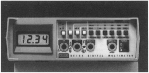
A VOM may be used to measure the resistance of a potentiometer, as shown in Fig. 2-4. If the shaft of the pot is adjusted while the ohmmeter is connected to points A and C, no resistance change takes place. The resistance of the potentiometer is measured in this way. Connecting to points B and C or to points B and A allows changes in resistance as the shaft is turned. The potentiometer shaft may be adjusted both clockwise and counterclockwise. This adjustment affects the measured resistance across points B and C or B and A. The resistance varies from zero to maximum and from maximum back to zero as the shaft is adjusted.
How to Measure Resistance with a VOM
Remember that resistance is opposition to the flow of electric current. For example, a lamp connected to a battery has resistance. Its resistance value is determined by the size of the filament wire. The filament wire opposes the flow of electric current from the battery. The battery causes current to flow through the lamp's filament. The amount of current through the lamp depends on the filament resistance. If the filament offers little opposition to current flow from the battery, a large current flows in the circuit. If the lamp filament has high resistance, it offers a great deal of opposition to current flow from the battery. Then a small current flows in the circuit.
Resistance tests are sometimes called continuity checks. A continuity check is made to see whether a circuit is open or closed (a continuous path). An ohmmeter also is used to measure exact values of resistance. Resistance always must be measured with no voltage applied to the component being measured. The ohmmeter ranges of a VOM are used to measure resistance. Electrical technicians often use this type of meter because it measures resistance, voltage, or current. When the rotary function-select switch is adjusted, the meter can be set to measure resistance, voltage, or current. The meter switch shown in Fig. 2-2 has the following settings:
1. Direct current (dc) voltage
2. Direct current (dc) amps and milliamps
3. Alternating current (ac) voltage
4. Resistance (ohms)
The lower right part of the function-select switch is for measuring resistance or ohms. The ohms measurement settings are marked as × 1, × 10, × 1000, and × 100,000. When measuring resistance with an ohmmeter, first put the test leads into the meter. The test leads usually are black and red wires that plug into the meter. The red wire is plugged into the hole marked volts-ohms-amps (V-Ω-A). The black wire is plugged into the hole marked negative common (–COM).
The scale of the meter is used to indicate the value of resistance in ohms. The right side of the scale is marked with a zero and the left side is marked with an infinity (∞) sign.
When the test leads are touched together, the needle on the scale of the meter should move to the right side of the scale. This indicates zero resistance. The needle of the meter is adjusted so that it is exactly over the zero mark. This is called zeroing the meter. This must be done to measure any resistance accurately. The ohms-adjust (ΩADJ) control is used to zero the needle of the meter. The meter should be zeroed before each resistance measurement is made.
It is important to be able to read the scale of the meter. The top scale shown in Fig. 2-3 is labeled with a zero on the right side and an infinity (∞) sign on the left side. This scale is used for measuring resistance only. The most accurate readings are made when the meter needle moves to somewhere between the center of the scale and zero because of the greater distance between the numbers on the right of the scale.
To measure any resistance accurately, first select the proper range. The ranges for measuring resistance are on the lower right part of the function-select switch. This switch has resistance ranges marked as × 1, × 10, × 1000, and × 100,000. If the range setting is on × 1, the reading on the meter scale must be multiplied by 1.
The meter must be zeroed whenever a range is changed. The test leads are then placed across a resistance. Assume that the needle of the meter moves to point A on the scale of Fig. 2-5. The resistance equals 7.5 × 1 = 7.5 Ω. Now change the meter range to × 1000. The reading at point B equals 5.5 × 1000 = 5500 Ω. At point C, the reading is 0.3 × 1000 = 300 Ω. The same procedure is used for the × 100,000 range. If the needle moves to 2.2 (point D) on the scale, the reading equals 2.2 × 100,000, or 220,000 Ω. If the meter range is set on × 100,000 and the needle moves to 3.9 (point E) on the scale, the reading is 3.9 × 100,000, or 390,000 Ω.

Remember to zero the meter by touching the test leads together and use the ohms-adjust control before making a resistance measurement. Each time the meter range is changed, the meter needle must be zeroed on the scale. If this procedure is not followed, the meter reading will not be accurate.
To learn to measure resistance, it is easy to use color-coded resistors. These resistors are small and easy to handle. Practice using the meter to measure several values of resistors makes reading the meter much easier.
Self-Examination
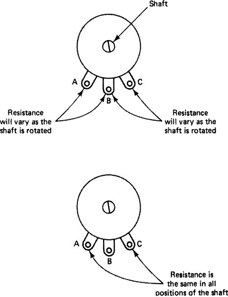
Refer to the Figure below and fill in the blanks with the values that correspond to the pointer location.
| Ohms range | A | B | C | D | E |
| R × 1 | (1) _____ | (6) _____ | (11) _____ | (16) _____ | (21) _____ |
| R × 10 | (2) _____ | (7) _____ | (12) _____ | (17) _____ | (22) _____ |
| R × 100 | (3) _____ | (8) _____ | (13) _____ | (18) _____ | (23) _____ |
| R × 1000 | (4) _____ | (9) _____ | (14) _____ | (19) _____ | (24) _____ |
| R × 10,000 | (5) _____ | (10) _____ | (15) _____ | (20) _____ | (25) _____ |

Answers
Measuring Voltage
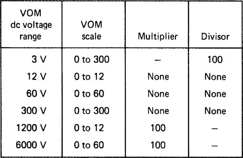
Voltage is applied to electric equipment to cause it to operate. It is important to be able to measure voltage to check the operation of equipment. Many electric problems develop because either too much or too little voltage is applied to the equipment. A voltmeter is used to measure voltage in an electric circuit. A VOM also can be used to measure voltage. In the controls of the VOM in Fig. 2-2 the voltage ranges are 3, 12, 60, 300, 1200, and 6000 V. When the function-select switch is adjusted to 3 V on the dc volts range, the meter measures up to 3 V. The same is true of the other ranges of dc voltage. The voltage value of each range is the maximum value of voltage that may be measured with the VOM set on that range.
When making voltage measurements, adjust the function-select switch to the highest range of dc voltage. Connect the red and black test leads to the meter by putting them into the proper jacks. The red test lead should be put into the jack labeled V-Ω-A. The black test lead should be put into the jack labeled –COM.
It is easy to become familiar with the part of the meter scale that is used to measure dc voltage. Refer to the VOM scale of Fig. 2-3. The part of the scale below the ohms scale is the dc voltage scale. This scale usually is black. There are three dc voltage scales: 0 to 12 V, 0 to 60 V, and 0 to 300 V. All dc voltages are measured with one of these scales. Each of the dc voltage ranges on the function-select switch corresponds to a number on the right side of the meter scale or a number that can be easily multiplied or divided by 10 to equal the number on the function switch.
When the 12, 60, or 300 V range is used, the scale is read directly. In these ranges, the number to which the needle points is the actual value of the voltage being measured. When the 3, 1200, or 6000 V range is used, the number to which the needle points must be multiplied or divided. If the meter needle points to the number 50 while the meter is adjusted to the 60 V range, the measured voltage is 50 V. If the needle points to the number 250 while the meter is adjusted to the 3 V range, the measured voltage is 2.5 V (250 ÷ 100 = 2.5). When the 1200 V range is used, the numbers on the 0 V to 12 V scale are read and then multiplied by 100. Most VOMs have several scales. Some of these scales are read directly, whereas others require multiplication or division.
Before making any measurements, choose the proper dc voltage range. The value of the range being used is the maximum value of voltage that can be measured on that range. For example, when the range selected is 12 V, the maximum voltage the meter can measure is 12 V. Any voltage higher than 12 V could damage the meter. To measure an unknown voltage (no indication of its value), start by using the highest range on the meter. Then slowly adjust the range downward until a voltage reading is indicated on the right side of the meter scale.
Matching meter polarity to voltage polarity is important in the measurement of dc voltage. The meter needle moves backward, possibly damaging to the meter, if polarities are not connected properly. Meter polarity is simple to determine. The positive (+), red, test lead is connected to the positive side of the dc voltage being measured. The negative (–), black, test lead is connected to the negative side of the dc voltage being measured. The meter is always connected across (in parallel with) the dc voltage being measured.
How to Measure DC Voltage with a VOM
Voltage is the electric pressure that causes current to flow in a circuit. A common voltage source is a battery. Batteries come in many sizes and voltage values. The voltage applied to a component determines how much current will flow through it.
A dc voltmeter or the dc voltage ranges of a VOM are used to measure dc voltage. The upper left part of the VOM function-select switch of Fig. 2-2 is used for measuring dc voltage. The dc voltage ranges are 3, 12, 60, 300, 1200, and 6000 V.
When measuring voltage with a VOM, first put the test leads into the meter. The red test lead is plugged into the hole marked volts-ohms-amps (V-Ω-A). The black test lead is plugged into the hole marked negative common (–COM). The scale of the meter is used to indicate voltage (volts). The left side of the dc voltage range is marked zero and the right side is marked 300, 60, and 12. The meter needle rests on the zero until a voltage is measured. These three scales are used to measure dc voltages on the sample meter scale.
To measure a dc voltage, select the proper range. The ranges for measuring dc voltage are on the upper left part of the function-select switch. If the range setting is on the 3 V, the voltage being measured cannot be larger than 3 V. If the voltage is greater than 3 V, the meter would probably be damaged. You must be careful to use a meter range that is larger than the voltage being measured. Each of the dc voltage ranges on the function-select switch corresponds to a number on the right side of the meter scale or a number that can be easily multiplied or divided to equal the number on the function-select switch. When the 12, 60, or 300 V range is used, the dc voltage scale is read directly. On these ranges, the number to which the needle points is the actual value of the voltage being measured. When the 3, 1200, or 6000 V range is used, the number to which the needle points is multiplied or divided by 100. If the meter needle points to the number 850 while the 3 V range is being used, the measured voltage is 8.5, because 850 ÷ 100 = 8.5.
Examples of dc voltage measurements with the meter set on the 3 V range follow. If the test leads of the meter are placed across a voltage source and the meter needle moves to point A on the scale of Fig. 2-6, the dc voltage is equal to 100 ÷ 100, or 1 V. The reading at point B is 165 ÷ 100, or 1.65 V. At point C, the reading is 280 ÷ 100, or 2.8 V. There is some difficulty in reading the voltage divisions on the scales. Look at the division marks from 200 to 250. The difference between 200 and 250 is 50 units (250 – 200 = 50). There are 10 division marks between 200 and 250. The voltage per division mark is 50 ÷ 10, or 5 V, per division. So each division mark between 200 and 250 equals 5 V. This procedure is like reading a ruler or other types of scales.

If the range switch is changed to the 12 V position, the voltage is read directly from the meter scale. For example, if the range is set on 12 V and the meter needle moves to point A in Fig. 2-6, the voltage is 4 V. The reading at point B equals 6.6 V. At point C, the reading is 11.2 V. The same procedure is used for all other ranges.
When measuring voltage, always be sure to select the proper range. The range used is the maximum value of voltage that can be measured on that range. For example, when the range selected is 12 V, the maximum voltage that the meter can measure is 12 V. Any voltage greater than 12 V could damage the meter. When measuring an unknown voltage, start with the highest range setting on the meter. Then slowly adjust the range setting to lower values until the meter needle moves to somewhere between the center and right side of the meter scale.
In measurement of dc voltage, polarity is important. The proper matching of meter polarity and voltage source polarity must be assured. The negative (black) test lead of the meter is connected to the negative polarity of the voltage being measured. The positive (red) test lead is connected to the positive polarity of the voltage. If the polarities are reversed, the meter needle will move backward and the meter might be damaged.
A certain amount of voltage is needed to cause electric current to flow through a resistance in a circuit. The voltage is called voltage drop. Voltage drop is measured across any component through which current flows. The polarity of a voltage drop depends on the direction of current flow. Current flows from the negative polarity of a battery to the positive polarity. In Fig. 2-7, the bottom of each resistor is negative. The top of each resistor is positive. The negative test lead of the meter is connected to the bottom of the resistor. The positive test lead is connected to the top. The meters are connected as shown to measure each of the voltage drops in the circuit. If the meter polarity were reversed, the meter needle would move in the wrong direction.

Measuring Current
Current flows through a complete electric circuit when voltage is applied. Many important tests are made by means of measuring current flow in electric circuits. The current values in an electric circuit depend on the amount of resistance in the circuit. Learning to use an ammeter to measure current in an electric circuit is important.
Most VOMs can be used to measure dc current. Refer to the controls of the VOM shown in Fig. 2-2. The function-select switch may be adjusted to any of five ranges of direct current, 12 A, 120 mA, 12 mA, 1.2 mA, and 60 μA. For example, when the function-select switch is placed in the 120 mA range, the meter is capable of measuring up to 120 mA of current. The value of the current set on the range is the maximum value that can be measured on that range. The function-select switch should first be adjusted to the highest range of direct current. Current is measured by connecting the meter into a circuit, as shown in Fig. 2-8. This is referred to as connecting the meter in series with the circuit.

Current flows from a voltage source when a device that has resistance is connected to the source. When a lamp is connected to a battery, a current flows from the battery through the lamp. In the circuit of Fig. 2-8, electrons flow from the negative battery terminal, through the lamp, and back to the positive battery terminal. Electrons are so small that the human eye cannot see them, but their movement can be measured with an ammeter.
As the voltage applied to a circuit increases, the current increases. If 12 V is applied to the lamp in Fig. 2-8, a larger current flows through the lamp. If 24 V is applied to the same lamp, an even larger current flows. As resistance gets smaller, current increases. Resistance is the opposition to current flow. When a circuit has more resistance, it has less current flow.
How to Measure DC Current with a VOM
Refer to the dc current ranges of the VOM shown in Fig. 2-2. The ranges begin with 12 A. The next ranges are for measuring 120 mA, 12 mA, 1.2 mA, and 60 μA. There are a total of five current ranges. The function-select switch is adjusted to any of these five ranges for measuring dc. When measuring current, make it a habit to start with the meter set on its highest range. Then move the range setting to a lower value if the meter needle moves only a small amount. The most accurate reading is obtained when the meter needle is between the center of the scale and the right side. The same scales on the VOM often are used for measuring dc and dc voltage.
If the meter range is set on the 12 A range, the scale is read directly. The bottom dc scale, which has the number 12 on the right side, is used. Some examples are shown in Fig. 2-9 with the meter set on the 12 A range. At point A on the scale the reading is 4.6 A. The reading at point B is 8.8 A.

The 60 μA range on the meter is for measuring very small currents. Measurements in this range are read directly from the meter scale. The number 60 is the middle number on the right of the dc scale.
When the meter is set on the 120 mA range, the meter measures up to 120 mA of direct current. The readings on the scale are multiplied by 10 on this range setting. The readings at the points shown in Fig. 2-9 for the 120 mA range are as follows:
![]()
![]()
![]()
![]()
The reading at point D is halfway between the 11.2 and 11.4 divisions on the scale, so the reading is 11.3 × 10, or 113 mA.
The test lead polarity of the VOM is important for measuring direct current. The VOM is connected to allow current to flow through the meter in the right direction. The negative test lead is connected nearest to the negative side of the voltage source. The meter is then connected into the circuit. To measure current, a wire is removed from the circuit to place the meter into the circuit. No voltage should be applied to the circuit while the current meter is being connected. The meter is placed in series with the circuit. Series circuits have one path for current flow.
The proper procedure for measuring current through point A in the circuit of Fig. 2-8 is as follows:
1. Turn off the voltage source of the circuit by opening the switch.
2. Set the meter to the highest current range (12 A).
3. Remove the wire at point A.
4. Connect the negative test lead of the meter to the negative side of the voltage source.
5. Connect the positive test lead to the end of the wire that was removed from point A.
6. Turn on the switch to apply voltage to the circuit.
7. Look at the meter needle to see how far it has moved up the scale.
8. Adjust the meter range until the needle moves to between the center of the scale and the right side.
Always remember the following safety tips when measuring current with a VOM:
1. Turn off the voltage before connecting the meter to prevent electric shock. This is an important habit to develop. Always remember to turn off the voltage before connecting the meter.
2. Set the meter to its highest current range. This assures that the meter needle does not move too far to the right of the scale and possibly damage the meter.
3. A wire is disconnected from the circuit and the meter is put in series with the circuit. Always remember to disconnect a wire and reconnect the wire to one of the meter test leads. If a wire is not removed to put the meter into the circuit, the meter will not be connected properly.
4. Use the proper meter polarity. The negative test lead is connected so that it is nearest the negative side of the voltage source. The positive test lead is connected so that it is nearest the positive side of the voltage source.
Self-Examination
Refer to Fig. 2-10 and fill in the blanks with the values that correspond to the pointer location.
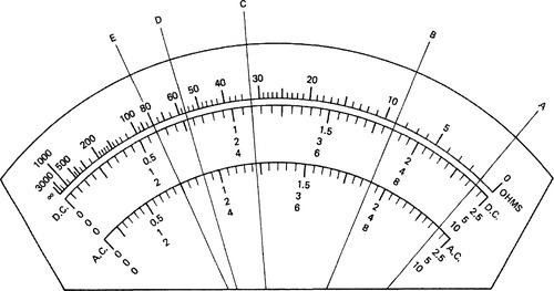
Figure 2-10
| DC volts range | A | B | C | D | E |
| 2.5 V dc | (26) _____ | (32) _____ | (38) _____ | (44) _____ | (50) _____ |
| 10 V dc | (27) _____ | (33) _____ | (39) _____ | (45) _____ | (51) _____ |
| 50 V dc | (28) _____ | (34) _____ | (40) _____ | (46) _____ | (52) _____ |
| 250 Vdc | (29) _____ | (35) _____ | (41) _____ | (47) _____ | (53) _____ |
| 500 V dc | (30) _____ | (36) _____ | (42) _____ | (48) _____ | (54) _____ |
| 1000 Vdc | (31) _____ | (37) _____ | (43) _____ | (49) _____ | (55) _____ |
| DC amps range | A | B | C | D | E |
| 10 A | (56) _____ | (64) _____ | (72) _____ | (80) _____ | (88) _____ |
| 2.5 A | (57) _____ | (65) _____ | (73) _____ | (81) _____ | (89) _____ |
| 500 mA | (58) _____ | (66) _____ | (74) _____ | (82) _____ | (90 _____ |
| 100 mA | (59) _____ | (67 _____ | (75) _____ | (83) _____ | (91) _____ |
| 50 mA | (60) _____ | (68 _____ | (76 _____ | (84) _____ | (92) _____ |
| 10 mA | (61) _____ | (69 _____ | (77) _____ | (85) _____ | (93) _____ |
| 2.5 mA | (62) _____ | (70) _____ | (78) _____ | (86) _____ | (94) _____ |
| 250 μA | (63) _____ | (71) _____ | (79) _____ | (87) _____ | (95) _____ |

Answers
Parallel Circuit Measurements
To measure current through path 1 in the parallel circuit of Fig. 2-11, use the following procedure:

1. Open the switch to make sure no voltage is applied to the circuit.
2. Remove wires 1 and 2 from point A. Set the meter to the highest current range.
4. Connect wires 1 and 2 to the positive test lead of the meter.
5. Connect the negative test lead of the meter to point A.
6. Turn on the switch to apply voltage to the circuit.
7. Adjust the meter, if necessary, to a lower range to obtain an accurate reading.
8. Read the current value on the scale of the meter.
To measure the resistance of a parallel circuit, first remove the voltage source. Prepare the meter to measure resistance. Be sure to zero the meter. Connect the meter across the points where the circuit was connected to the voltage source (points A and B in Fig. 2-11a). Adjust the meter range, if necessary, to get an accurate resistance reading. Be sure to zero the meter each time a change of ranges is made. Once the proper range is selected, accurately read the resistance on the meter scale.
Combination Circuit Measurements
To measure the total resistance of the circuit of Fig. 2-12, first remove the voltage source from the circuit. Prepare the meter to measure resistance. Be sure to zero the meter. Connect the meter across points A and C. These points are where the voltage source was connected into the circuit. Adjust the meter range if necessary to obtain an accurate resistance reading. Once the proper range is selected, read the measured resistance on the meter scale.
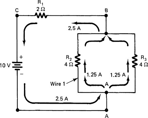
To measure the current through R1; first make sure that no voltage is applied to the circuit. Remove the wire at point C. Set the VOM to the highest current range. Connect the negative VOM test lead to point C and the positive test lead to the positive power source terminal. Now apply voltage to the circuit. Adjust the meter, if necessary, to a lower range to obtain an accurate current reading. Then read the current value on the scale of the meter. The current through R1, should equal 2.5 A. This value is the same as the total current (IT) of the circuit because R1 is a series resistor.
To measure the current through R2 in this combination circuit, use the same procedure as for any parallel path. The following procedure should be followed:
1. Make sure that no voltage is applied to the circuit.
2. Remove wire 1 from point A.
3. Set the meter to its highest current range.
4. Connect wire 1 to the positive test lead of the meter.
5. Connect the negative test lead of the meter to point A.
6. Apply voltage to the circuit.
7. Adjust the meter, if necessary, to a lower current range to obtain an accurate reading.
8. Read the current value on the scale of the meter. The current through R2 should be 1.25 A.
To measure the voltage across R1, connect the negative meter lead to point B and the positive lead to point C. The voltage should equal 5 V. The voltage across R2 equals the voltage across R3, because they are in parallel. The negative meter lead is connected to point A and the positive lead to point B. The voltage across R2 and R3 should be 5 V.
Digital Meters
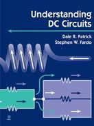
Many digital meters are now in use. They have numerical readouts to simplify measurement and to make the measurements more accurate. Instruments such as digital counters, digital multimeters, and digital voltmeters are commonly used. Digital meters such as the ones shown in Fig. 2-13 rely on the operation of digital circuitry to produce a numerical readout of the measured quantity.
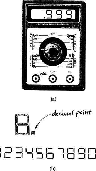
The readout of a digital meter is designed to transform electric signals into numerical data. Both letter and number readouts are available, as are seven-segment, discrete-number, and bar-matrix displays. Each method has a device designed to change electric energy into light energy on the display.
Self-Examination
Use the meter you will be using for completing experiments. Study the meter and answer each of the following questions. Either an analog or digital meter may be used. If the self-examination item does not apply to your meter, place N/A in the blank.
96. What company manufactured the meter? _____
97. What is the model number of the meter? _____
98. The meter will measure up to _____ A of dc.
99. Alternating current is read on the _____colored scales.
100. True or False: The ohms-adjust control is used each time the resistance range is changed. _____
101. To measure dc greater than 1 A, the range switch is placed in the _____ position.
102. For measuring current in a circuit, the meter should be connected in (series or parallel) _____.
103. For measuring voltage, the meter should be connected in (series or parallel) _____.
104. To measure 18 mA of current, the range switch should be placed in the _____ position.
105. To measure 10 μA of current, the range switch should be placed in the _____ range.
106. To measure resistance, the red test lead must be placed in the jack marked _____ and the black test lead in the jack marked _____.
107. The most accurate resistance reading is located on the (right or left) side of the meter scale. _____
108. True or False: Polarity must be observed when measuring ac voltage. _____
109. True or False: Polarity is not important when measuring resistance. _____
110. Up to _____V can be measured with the meter.
111. For measuring a resistor valued at 10 Ω, the _____ range should be used.
112. True or False: Polarity must be observed when measuring dc. _____
113. True or False: It is correct to measure the resistance of a circuit with voltage applied. _____
114. True or False: When measuring an unknown value of voltage, one should start at the highest scale and work down to the correct scale. _____
115. True or False: Meters should be handled with care and safety. _____
Answers
EXPERIMENT 2-1
MEASURING RESISTANCE
Resistance is the term used to describe the opposition encountered by electric current flow. Resistance is measured in ohms (Ω). In unit 1, you learned how to determine the value of a resistor by examining its color bands. However, the resistance of many components cannot be determined through observation and therefore must be measured.
This lab is designed for an analog meter so that scale interpretation may be learned. Simple changes will easily allow use of a digital meter, if desired.
OBJECTIVE
To learn how to measure resistance with the ohmmeter portion of a multimeter.
EQUIPMENT
Multimeter (VOM)
Potentiometer: 5 kΩ
Resistors: 10 Ω, 15 Ω, 220 Ω, 470 Ω, 1 kΩ, 5.1 kΩ, 68 kΩ, 100 kΩ, 220 kΩ, 1 MΩ
PROCEDURE
1. The multimeter, or VOM, is the meter most often used for basic electronics work. A VOM can be used as an ammeter, a voltmeter, or an ohmmeter. Simply adjust the function-select switch for the desired function. Fig. 2-2 shows the controls, including the function-select switch, of a common VOM.
The function-select switch is in the center of some circular divisions and acts as a dial. A portion of the circular divisions is designated the ohms function. The area of the divisions located within the ohms-function space is divided into four positions: × 1, × 100, × 1000, and × 1 00,000. The meter you are using may be slightly different from the one illustrated. Nevertheless, it exhibits the same basic characteristics as the VOM shown. Adjust the function-select switch on your meter to the ohms function. List the different positions in the ohms-function area on your meter._____
2. Now that you have adjusted the VOM to the ohms function, connect the test leads to the meter. The test leads used with the VOM usually are red and black. The colors are used to help you differentiate the positive and negative polarities of the meter. For our purposes red indicates the positive polarity (+), and black indicates the negative (–) polarity. Look at the meter controls in Fig. 2-2. In your VOM insert the red test lead into the hole or jack marked with (+) and the black test lead into the hole or jack marked with (–). (Note:The meter you are using may be different from the one illustrated. If this is so, plug the red and black test leads into the appropriate jacks and proceed.) Touch the test leads together. Describe what happens to the needle located on the scale of the meter._______
3. You have now adjusted the function-select switch to the ohms function of the VOM, inserted the proper test leads into the proper jacks, and seen that when the test leads are touched together, or shorted, the needle of the meter moves from the extreme left-hand side of the meter scale to the extreme right-hand side. If you are using a DVM, the display will indicate 0. When the leads are not touched together, the digit 1 will appear on the left display in most cases. The 1 indicates infinite resistance.
4. You should now become familiar with the scale of the meter. Fig. 2-3 is a scale of a very commonly used VOM. If you are using a DVM, skip this section.
The top scale (from 0 to ∞, labeled ohms) is used for measuring ohms only. On most VOMs, the top scale is designated as the ohms scale. Record the location and color of the ohms scale on your meter.

5. To measure any resistance in ohms, you must select the proper position or range. On the meter illustrated in Fig. 2-2, there are four ranges: × 1, × 10, × 1000, and × 100,000. The ohmmeter must be properly zeroed before any attempt is made to accurately measure resistance. To zero the ohmmeter, short the two test leads together. This should cause the needle to move from infinity (∞) on the left to zero (0) on the right. Infinity represents a very high resistance, whereas zero represents a very low resistance. If the needle does not reach zero or if it goes past zero when the test leads are shorted, the control marked ohms adjust must be used to adjust the needle to rest on zero when the test leads are touched together. There will be a similar adjustment on your VOM if yours is different from the one illustrated. Adjust the VOM to each of its ranges: × 1, × 10, × 1000, and × 100,000 and zero the meter for each of these ranges. The ohmmeter must be zeroed before each resistance measurement and after each range change. Otherwise your measurements will be incorrect.
6. The ohms scale on the meter is nonlinear. The divisions on the right side of the scale are farther apart than those on the left side. This provides a more accurate measurement of resistance when the needle of the meter deflects and stops somewhere between the center of the ohms scale and zero.
Choosing the proper range adjustment controls where the needle deflects. Adjust the function-select switch to the × 1 range of the ohms function. Zero the meter, and then connect it across a 10 Ω resistor. Record the precise resistance (in ohms) indicated by the needle on the ohms scale in Fig. 2-1A. The range selected for this operation was × 1, which means that the number to which the needle points will be multiplied by 1.

Figure 2-1A
7. Adjust the function-select switch to the × 100,000 range. Zero the meter and connect it to a 100 kΩ resistor, as illustrated in Fig. 2-1B. Record the resistance (in ohms) shown by the needle on the ohms scale. The range selected for this measurement is × 100,000, which means that the number to which the needle points will be multiplied by 100,000.
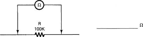
Figure 2-1B
8. Measure and record the values of the resistors indicated in Fig. 2-1C. Remember to choose a meter range that will cause the needle to deflect somewhere between the center of the scale and zero. Always zero the meter when changing ranges, and always multiply the number indicated on the scale by the multiplier of the chosen range: × 1, × 100, × 1000, × 100,000. Never measure the resistance of a component until it has been disconnected.

Figure 2-1C
9. Using the proper procedure for measuring resistance, measure and record the precise resistance of the 200 Ω pot illustrated in Fig. 2-1D.
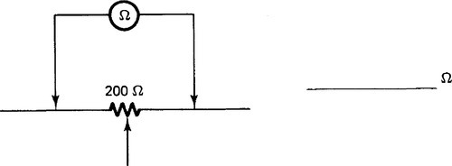
Figure 2-1D
10. Adjust the control of the pot while the ohmmeter is connected. Describe how this action affects the measured resistance of the pot.______
11. Alter the connections of the pot as illustrated in Fig. 2-1E.
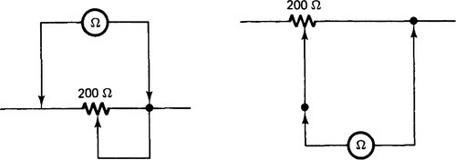
Figure 2-1E
12. Adjust the pot both clockwise and counterclockwise and describe how this action affects its measured resistance._____
ANALYSIS
1. Why is the ohms scale of an analog multimeter considered to be nonlinear? _____
2. Where on an analog ohms scale are the most accurate measurements found? _____
3. What is meant by the × 1000 range on the ohm meter? _____
4. What is meant by zeroing the ohmmeter? _____
5. Why is it necessary to zero the ohmmeter? _____
6. If the range of the ohmmeter was set to × 100,000 and the needle pointed to 0.6 on the ohms scale, what would be the value of the resistance being measured? _____
EXPERIMENT 2-2
MEASURING VOLTAGE
Voltage is the force that causes electric current to flow through conductors or paths. This force, sometimes called electromotive force (EMF), is measured in volts. It is essential that anyone involved in electronics work be able to use the necessary equipment to measure voltage accurately.
This lab is designed for an analog meter so that scale interpretation may be learned. Simple changes allow the use of a digital meter, if desired.
OBJECTIVES
1. To learn to measure voltage with a multimeter.
2. To construct basic electric circuits.
EQUIPMENT
Multimeter (VOM)
Potentiometer: 5 kΩ
Resistors: 470 Ω, 1 kΩ
6 V battery or power supply
6 V lamp with socket
Connecting wires
PROCEDURE
1. You learned in Experiment 2-1 that a multimeter can be used to measure resistance. A multimeter also can be used to measure voltage. Experiment 2-1 showed that the function-select switch can be adjusted to cause the multimeter to perform many measurement functions with several different ranges. The dc voltage ranges of the meter shown in Fig. 2-2 are 3, 12, 60, 300, 1200, and 6000 V. When the function-select switch is adjusted to 3 V on the dc volts range, the meter can be used to measure a maximum of 3 V. The same is true of the remaining ranges within the dc volts function. The numerical value of the chosen range indicates the maximum value of voltage that may be measured on that range. The meter you are using may differ somewhat from the VOM illustrated in Fig. 2-2. Nevertheless, it will exhibit the same basic characteristics as the one described.
2. Adjust the function-select switch on your meter to the lowest range of the dc volts function. List the different ranges within the dc volts function on your meter.
_____, _____, _____,
_____, _____
3. Connect the red and black test leads to the meter by inserting the appropriate ends into the proper jacks on the face of the meter. The red test lead should be inserted into the jack labeled (+) and the black test lead should be inserted into the jack labeled –COM. (Note: The meter you are using may be different. If this is the case, plug the red and black test leads into the appropriate jacks and proceed.)
4. You now have the VOM properly equipped and adjusted to measure dc volts. You should now become familiar with the portion of the scale of the meter used for measuring dc volts. Figure 2-3 shows the scale of a very commonly used VOM. The scale immediately under the ohms scale is the dc volts scale. There are three dc volts scales: 0 to 12 V, 0 to 60 V, and 0 to 300 V. All dc voltages are measured with one of these scales. The question becomes, What scales are to be used with what meter ranges? Each of the dc voltage ranges corresponds to a number on the right side of the meter scale or a multiple or divisor of that number. Figure 2-2A indicates the proper scale to be read for each dc voltage range.
5. When you choose the 12 V, 60 V, or 300 V range, you read the scale directly. In these ranges, the number to which the needle points is the actual value of the voltage being measured. When you select the 3 V range, the number to which the needle points must be divided by 100. For example, if the needle of the meter points to 50 while the meter is adjusted to the 3 V range, the measured voltage is 0.5 V. (Note: The meter you are using may differ slightly from the one described. VOMs usually have several scales. Some of these scales can be read directly, whereas others necessitate use of a multiplier or divisor. If your VOM is different, identify the scales that can be read directly and the ones that must be used with multipliers or divisors.)
6. Complete Fig. 2-2B by indicating the proper voltage scale and voltage value. Show the multiplier or divisor for the voltage range for the meter scale shown. This will give you practice using a meter scale.

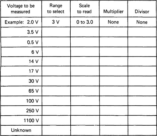
7. You are now almost ready to measure dc voltage. Before actually doing so you should become familiar with some facts about choosing the dc voltage range. Recall from step 1 that the numerical value of the chosen range indicates the maximum value of voltage that may be measured on that range. When the range selected is 12 V, the maximum voltage that the meter can measure is 12 V. Any voltage above 12 V could damage the meter on this range. This is true for most voltage scales on most VOMs. If you are trying to measure a voltage that is totally unknown (no indications as to its approximate value), you should start the measuring procedure by choosing the highest range on your meter and slowly adjusting the range downward until a voltage reading is indicated on the upper or right-hand half of the meter scale. Complete Fig. 2-2C by showing the proper meter range to be selected, the proper meter scale to be read, and the proper multiplier and divisor to be used with each voltage to be measured. Use the scale of your meter to complete the figure.
8. You need to consider meter polarity when measuring dc voltage. Correct matching of meter polarity to voltage polarity is vital. If proper care is not exercised, the meter will deflect backward, and the internal components will be damaged. Meter polarity is simple to determine. The positive (+), red, test lead is connected to the positive side of the dc voltage to be measured. The negative (–), black, test lead is connected to the negative side of the dc voltage to be measured.
9. Measure and record the actual voltage of a 6 V battery. The voltmeter is always connected across the voltage, or in parallel with the voltage to be measured.
Actual voltage of battery = _____V
10. Construct the circuit illustrated in Fig. 2-2D. Measure and record the voltage supplied by the battery and the voltage across the lamp.
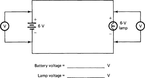
Figure 2-2D
11. A certain amount of voltage is always necessary to cause current flow. This voltage is called the voltage drop and is found across any component through which current flows. The polarity of this voltage drop is determined by the direction of the movement of electrons from negative to positive. Thus if electrons were moving through a resistor in the direction shown in Fig. 2-2E, the left side of the resistor would be negative (–) and the right side would be positive (+). The black test lead of the meter would be connected to the left side of the resistor and the red test lead would be connected to the right side. This procedure would measure the voltage drop developed across this resistor. In the illustrations of Fig. 2-2F, indicate the proper meter polarity for measuring the voltage drop across each resistor.
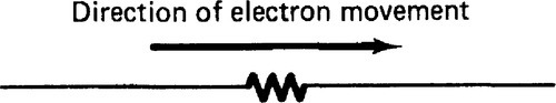
Figure 2-2E
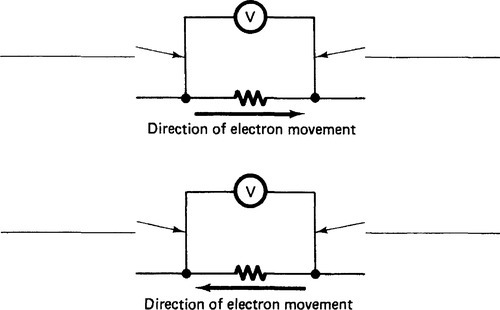
Figure 2-2F
12. Construct the circuit of Fig. 2-2G. Measure and record the battery voltage and the voltage drops across R1 and R2. Remember that electrons move from negative to positive.

Figure 2-2G
13. Construct the circuit of Fig. 2-2H. Measure and record the voltage drops across R1 and R2.

Figure 2-2H
14. Construct the circuit shown in Fig. 2-21.

Figure 2-21
15. Adjust the potentiometer both counterclockwise and clockwise and record the voltages.
Counterclockwise voltage = _____V
Clockwise voltage = _____V
ANALYSIS
1. What is voltage? _____
2. If you were measuring an unknown voltage what meter range would you choose? Why? _____
3. What determines the polarity of a voltage drop developed by a resistor through which electrons are moving? _____
4. What causes the voltage drop developed across any component through which electrons are moving? _____
5. When is it necessary to use a multiplier or divisor with a scale on an analog multimeter? _____
6. How is the proper range of a multimeter selected? _____
7. Could 4 V be measured on the 3 V range of a multimeter? Why?
8. Indicate the proper range of your meter for measuring the following dc voltages:
EXPERIMENT 2-3
MEASURING CURRENT
Current is the movement of electrons from one location to another through conductors or paths. Current is measured in amperes (the number of electrons moving past a given point in a circuit per second), milliamperes (0.001 A), or microamperes (0.000001 A). It is essential that anyone involved in electronics work learn to measure current values accurately.
An analog meter is used in this activity so that scale interpretation can be learned. Simple changes allow the use of a digital meter, if desired.
OBJECTIVES
1. To learn to measure current with an ammeter.
2. To construct basic electric circuits.
3. To convert amperes to milliamperes or microamperes and vice versa.
EQUIPMENT
Multimeter (VOM)
Resistors: 220 Ω, 1 kΩ, 100 kΩ, 220 kΩ
6 V battery or power supply
SPST switch
Connecting wires
PROCEDURE
1. You have learned from previous experiments that a VOM can be used to measure resistance and voltage. In addition to these electric quantities, current can be measured with a VOM. Figures 2-2 and 2-3 show the controls and the scale of a common VOM. The function-select switch controls the measurement function and the range of the VOM. Figure 2-2 indicates that the function-select switch may be adjusted to one of five ranges within the dc function, namely, 12 A, 120 mA, 12 mA, 1.2 mA, and 60 μA. Thus when the function-select switch is placed in the 120 mA position within the dc function, the meter can be used to measure a maximum of 120 mA. The other dc current ranges of the VOM are similarly arranged. The numerical value of the chosen range shows the maximum value of current that can be measured on that range.
2. The meter you are using may differ somewhat from the illustrated VOM. It should, however, exhibit the basic characteristics of the one described. Adjust the function-select switch on your meter to the lowest range of the dc function. List the different ranges for measuring dc on your meter._____, _____, _____,_____, _____
3. Plug the black and red test leads into the jacks labeled (–) and (+), respectively. (Note: If your meter is different from the one illustrated, plug the test leads into the appropriate jacks and proceed.)
4. You are now ready to become familiar with the portion of the scale of the meter used for measuring direct current. Figure 2-3 illustrates the scale of a commonly used VOM. Three scales are used for measuring dc. They are the same as those used to measure dc voltage. Five dc ranges can be used with this meter. All current measurements are read on these scales with the proper multiplier or divisor. Figure 2-3A shows the proper multiplier or divisor to be used with the dc scales for any of the five ranges. (Note: Your meter may have different scales and multipliers from those in Fig. 2-3A. Identify them and proceed.)

5. Each range of dc has a specific multiplier or divisor or is read directly on the scale. For example, if the needle of the meter points to the number 6 on the dc scale, and the meter is adjusted to the 12 mA range, the measured current is 6 mA. If the needle points to 6 while the meter is adjusted to the 120 mA range, the measured current is 60 mA (6 × 10 = 60, or 6 ÷ 0.1 = 60).
6. Complete Fig. 2-3B by determining the proper current value when the needle points to a specific number. Also determine the correct multiplier and divisor to be used with the indicated current range. You should use the equivalent ranges, scales, multipliers, and divisors of the meter in Figs. 2-2 and 2-3.

7. Most VOMs can be used to measure currents greater than 1 A. Up to 12 A of current may be measured with the meter illustrated. The numerical value of the chosen range indicates the maximum value of current that can be measured in that range. For example, when the range selected is 12 mA, the meter can be used to measure a maximum of 12 mA. Any current above 12 mA could damage the meter in this range. This is true for most current scales of most VOMs. If you are trying to measure an unknown current (no indication of its approximate value), start the measuring procedure by choosing the highest range on your meter and slowly adjusting the range downward until a current reading is indicated on the scale. Complete Fig. 2-3C by indicating the proper meter range to be selected and the proper multiplier and divisor to be used with each value of current to be measured. (Note: Always select the smallest range that will allow you to measure the current.) Use your meter's ranges and scales for completing Fig. 2-3C.

8. Meter polarity of the VOM is important when measuring current. The VOM must always be connected in such a way as to allow the current to flow through the meter in the proper direction. Otherwise the needle will deflect backward, possibly causing internal damage to the meter. If current is to flow through the meter in the proper direction, consideration must be given to the direction of current. Current flows from negative to positive; thus if the meter is connected correctly into a circuit, current will flow through the black test lead (–), through the meter, and then through the red test lead (+). The illustration of Fig. 2-3D should be helpful.

Figure 2-3D
9. In the illustrations of Fig. 2-3E show which test leads should be red (+) and which should be black (–) for the current meters indicated.

Figure 2-3E
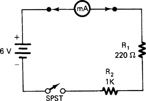
10. Adjust the VOM to the dc function 120 mA range (or equivalent) and connect it into the circuit, as illustrated in Fig. 2-3F. Be sure to observe the proper meter polarity.

11. Close the SPST switch and record the current indicated by the VOM: _____ mA, or _____ A.
12. Open the SPST switch and add the additional resistor illustrated in Fig. 2-3G.
13. Change the range of the VOM to 12 mA (or equivalent), and close the switch. Record the current indicated on the VOM: _____ mA, or _____ A.
14. Disconnect the circuit of Fig. 2-3G and connect the circuit of Fig. 2-3H.

15. Set the VOM to the 60-pA range (or equivalent), and connect the meter into the circuit, observing proper polarity. Close the switch and record the current: _____ μA, or _____ mA, or _____ A.
16. Disconnect the circuit illustrated in Fig. 2-3H.
17. Construct the circuit illustrated in Fig. 2-3I.
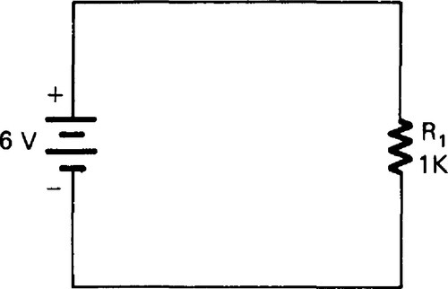
Figure 2-3I
18. Adjust the VOM to the 12 mA range (or equivalent) and connect it into the circuit illustrated in Fig. 2-3I, observing proper polarity. Record the current: _____ mA, or _____ A.
ANALYSIS
1. What is current? ______________________________________
2. What does each of the dc ranges on your multimeter indicate? _________________________________
3. Describe how a multimeter is properly connected into a circuit to measure current. _________________________________
4. Why is proper polarity important to observe when measuring dc current? _________________________________
5. What meter ranges would be selected on your meter to measure the following currents? _____
6. What is the proper procedure to follow when attempting to use a multimeter to measure an unknown current? _________________________________
7. What is the proper procedure to be followed when attempting to use a multimeter to measure a current greater than 2 A? _________________________________
EXPERIMENT 2-4
FAMILIARIZATION WITH POWER SUPPLY
The variable dc power supply is an electronic circuit that changes alternating current (ac) into dc. This circuit is usually housed in a case or protective enclosure. Output jacks are provided for external connections. This type of power supply usually has some means by which the output voltage can be adjusted from zero (0) to a maximum value. The symbol for the variable dc power supply is illustrated in Fig. 2-4A.
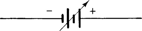
Figure 2-4A
OBJECTIVE
To become familiar with the use of a power supply to provide dc voltage to an electronic circuit.
EQUIPMENT
Multimeter (VOM)
1.5 V dry cell
Variable dc power supply
Resistor: 100 Ω
PROCEDURE
1. A dry cell or battery can be used as a simple power source for a circuit. Acquire the 1.5 V dry cell and prepare the VOM to measure dc voltage. Measure and record the precise voltage across the cell: _____ V.
2. Construct the circuit illustrated in Fig. 2-4B.

3. The circuit represents a dry cell in a loaded state (large current output). Measure the dry cell voltage with it loaded as shown in Fig. 2-4B: _____V.
4. How did the voltage measured in step 1 compare with the measured voltage in step 3? How do you account for any difference? _________________________________
5. In Fig. 2-4C, make a simple sketch of the variable dc power supply that you will use for this and future experiments. Include in your sketch all controls, output jacks, and range switches, where applicable.
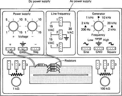
6. A common type of power supply is shown in Fig. 2-4D.
7. Adjust the VOM to measure dc voltage. Connect it to the dc output jacks of the power supply. These are usually labeled (+) and (–) or ground.
8. Turn on the power supply and adjust it to produce maximum dc voltage. Record the maximum voltage measured on the VOM.
Maximum voltage = _____ V.
9. Adjust the variable dc voltage control on the power supply to cause it to produce different voltages measured with the VOM. What is the voltage range of your power supply?
Range = _____V to_____V.
10. Turn off the power supply and disconnect the VOM.
11. If the power supply operating instructions are available, read them thoroughly.
ANALYSIS
1. Why is it considered correct to check the condition of a dry cell while it is loaded? _________________________________
2. What are some advantages of using dry cells? _________________________________
3. What are some advantages of using a variable dc power supply? _________________________________
4. Draw the symbols for a dry cell and a variable dc power supply.
5. What is meant by the term ground? _________________________________
6. Draw the symbol for a ground.
Measuring Voltage, Current, and Resistance
Instructions: For each of the following, circle the answer that most correctly completes the statement.
1. A VOM is an example of a
a. Multifunction meter
b. Single-function meter
c. Galvanometer
d. High-resistance meter
2. For measuring voltage, the meter is connected in
a. Series
b. Parallel
c. Series-parallel
d. Either series or parallel
3. For measuring current flow, the meter is connected in
a. Series
b. Parallel
c. Series-parallel
d. Either series or parallel
4. The ohmmeter setting that would be best when checking the continuity of a fuse is:
a. R × 1
b. R × 10
c. R × 1000
d. R × 100,000
5. The current indicated on the analog meter scale of Figure 2E-5 is
a. 5 A
b. 25 A
c. 5 mA
d. 25 mA
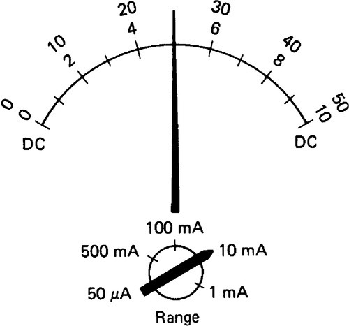
Figure 2E-5
6. When measuring resistance with an ohmmeter, a short indicates
a. Infinite resistance
b. Zero resistance
c. Midscale resistance
d. Cannot measure a short with an ohmmeter
7. The current indicated on the meter scale of Figure 2E-7 is
a. 100 mA
b. 200 mA
c. 10 mA
d. 2 mA

Figure 2E-7
8. The current indicated on the analog meter scale of Figure 2E-8 is
a. 40 A
b. 8 A
c. 40 mA
d. 8 mA

Figure 2E-8
9. The current indicated on the analog meter scale of Figure 2E-9 is
a. 5 mA
b. 25 μA
c. 25 mA
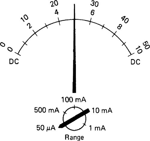
Figure 2E-9
10. A major precaution to observe when measuring resistance with an ohmmeter is to make sure
a. Circuit power is turned off
b. Circuit power is turned on
c. Range switch is set on maximum setting
d. Polarity is observed
True-False: Place either T or F in each blank.
| ___11. | When using a multimeter to measure dc voltage, polarity should be observed. |
| ___12. | Ohms adjust should be used each time the resistance range is changed. |
| ___13. | For measuring current flow, the meter should be connected in series. |
| ___14. | For measuring volts, the meter should be connected in parallel. |
| ___15. | The most accurate ohms reading of an analog multimeter is found on the left side of the ohms scale. |
| ___16. | Polarity is important when measuring ac volts. |
| ___17. | Polarity is not important when measuring resistance. |
| ___18. | For measuring a resistor valued at 10 Ω, the × 1 scale of an ohmmeter should be read. |
| ___19. | It is considered good practice to measure the resistance of a circuit with voltage present in the circuit. |
| ___20. | When measuring an unknown value of dc voltage, one should start at the highest range and work down to the correct range. |