2
Propulsion System Adjustable Speed Drive
Traditionally, the ship propulsion system propeller directly driven by the prime mover or through gear box has many mechanical challenges such as a long drive shaft and shaft alignment, and complex gear box.
The VFD for propulsion systems has gained popularity due to drive technology maturity for the following:
- The propulsion shaft need not be in line with the engine.
- The propulsion motor can be very close to the propeller, with total elimination of propulsion shaft and shaft alignments.
- Electrical speed and torque control of the propulsion.
- Electrical system smooth ramp‐up and down of the ship speed.
- Propulsion diesel engines running at a synchronous speed for generator.
- Eliminating propulsion engine noise due to varying engine speed.
- The diesel engine location is variable as DG can be in any convenient location.
- Ease of using solid state technology.
The shipboard power system design process has become very complex due to high power generation and variable drive. Traditional design experience is not sufficient to support the new challenges of high power generation, high power consumables, such as electrical propulsion, and other adjustable drive ship service applications. Traditional protection systems such as over load and short circuit protection is not sufficient. This book addresses both design and development issues namely:
- System design process with VFD.
- System developmental process with VFD.
- Verification of the Design & Development with VFD for regulatory requirements.
- Verification of failure mode and effects of the VFD design.
- Verification of training requirements for the VFD design.
- Verification of operator readiness for VFD equipment.
2.1 The Shipboard Propulsion Power ASD/VFD Anomalies
See Table 2.1.
Table 2.1 VFD Influence on Shipboard Power System.
| Item | Issues | Causes | Discussion |
| 1 | Premature motor failure | High frequency components of the inverter output creating electrical noise such as (a) Electromagnetic interference (EMI); Electromagnetic radiation and Electromagnetic induction (b) Circulation of common mode current, (c) Reflected wave |
Electromagnetic radiation – Can damage equipment, and the drive Traditional three conductor cable will act as a large radiating loop antenna effecting shipboard electrical control system, radio devices and alarms. Specially designed power cable with shielding and drain wire will manage these problems, however, cable procurement, termination, and routing must be properly done.
Electromagnetic Induction – VFD induces magnetic field by rectifying AC to DC and then inverting DC to AC by the use of switching at a very high rate. Common mode Current – In ideal situation there should not be any common mode current. However, the common mode current can be the conductor current plus ground current plus the shield current. The common mode current interferes with communication network, and low voltage/low current signals. Common mode current can flow through motor bearing, resulting premature motor failure. |
| 2 | Premature VFD cable failure | VFD cable will have the following additional features: Overall shield, Symmetrically designed conductors, and better insulation. Better insulation is necessary to increase resistance to high voltage peaks and high dv/dt. | |
| 3 | Malfunction of other vital shipboard equipment including shutdown | ||
| 4 | Malfunction of VFD related equipment | ||
| 5 | Proliferation of harmonic in the LV distribution and MV distribution and effecting auxiliary systems and contributing to malfunction |
2.2 Shipboard Electrical Propulsion System With Adjustable Speed Drive and Ship Service Power With Transformer and Motor‐Generator (MG) Set (Figure 2.1 and 2.2)
The propulsion power requirement is usually much higher than the other ship service loads. The propulsion load with variable frequency drives and transformer, the current inrush can create a disturbance in the main bus. The shipboard power system must be designed so that any combination of generators can support the load requirements without any concern of high current inrush.
If a large transformer is used, pre‐magnetizing system should be considered current inrush. The pre‐magnetization system initially energizes the secondary of the propulsion transformers prior to connecting the transformer primary to the main bus. This in effect pre‐magnetizes the transformer core and aligns the transformer magnetic field, so that the starting current inrush is negligible when the transformer main circuit breaker is closed.

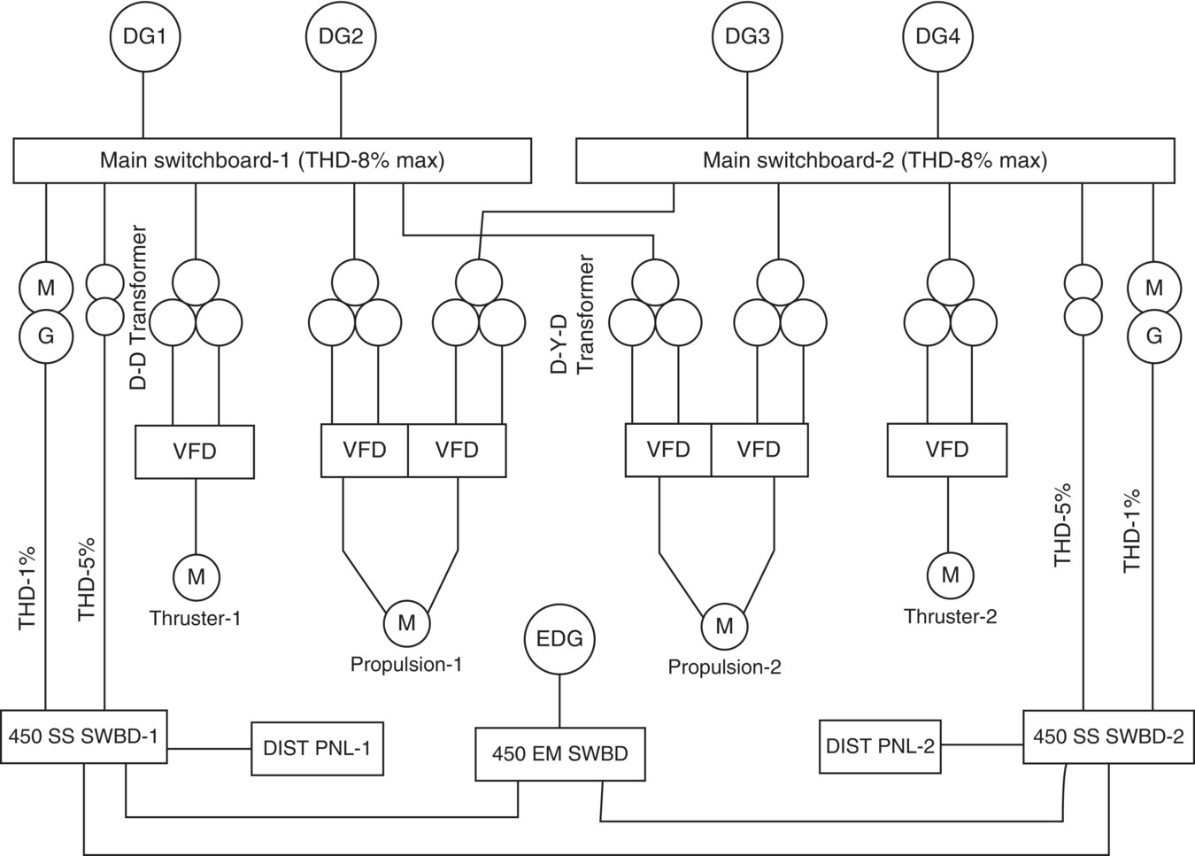
Figure 2.1 Typical electrical propulsion with variable speed controller and ship service switchboard is fed from a transformer and MG set (MG set is for clean power consideration).

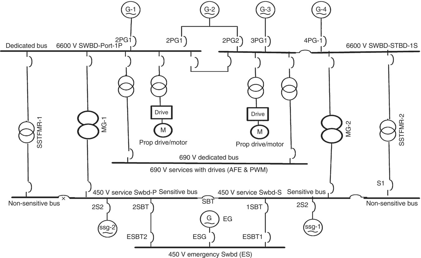
Figure 2.2 Typical Variable Speed Electric Propulsion System With Ship Service Transformer For Non‐Sensitive Loads And MG Set For Sensitive Loads.
There are four ship service generators, two ship service switchboards, one emergency generator, and one emergency switchboard. Each ship service switchboard is connected to two ship service generators. This set‐up is for ships with a large service load demand, such as cruise ships. Due to the number of generators, the load distribution and management of four ship service generators and one emergency generator can be complex. However, the design has proven to be very successful. The parallel operation and necessary protective control and their interlocking must however be clearly understood by the operator as shown:
-
- Ship service bus tie breaker section
- Emergency switchboard—120 V section
- Emergency lighting
- Other 115 V emergency loads
- Other 115 V services
- Emergency switchboard—480 V section
- Emergency generator circuit breaker
- 480 V emergency loads
- Ship service bus tie breaker section
Figures 2.1 and 2.2 are typical shipboard power generation and distribution systems delivering power to a lube oil pump. The main generator is delivering 6600 V power to a 6600 V switchboard. The 6600 V switchboard is delivering power to the 480 V ship service switchboard through a step down transformer. Motor generator is also added as an alternative to ensure the 480 V ship service bus type‐1 power quality.
2.3 VFD System Design Verification
A design is to meets fundamentals of the requirements by contract specification, which is presentation in an electrical one‐line diagram such as Figure 2.1. The basic verification is outlined in the USCG regulations called failure mode and effect analysis (FMEA) supported by qualitative failure analysis (QFA) and design verification test procedure (DVTP).
Four 6600 V generators are to generate power by using any one of the three generators keeping one generator spare to meet regulations.
The 6600 V switchboard is shown with bus‐tie circuit breaker. This is a requirement. There are ways to meet this requirements which will be further discussed in various sub‐sections in this chapter.
- 6600 V 3 phase, 60 Hz switchboards
- 450 V Ship service switchboard. The power is delivered by transformer 6600 V/450 V, three‐phase transformers
- 450 V Vital power distribution panel with circuit breaker for the auxiliary motor. The motor feeder must be of sufficient size to ensure load carrying capability. The motor controller overload thermal unit must be sized to protect the system from overload. The circuit breaker in the 450 V distribution panel must be sized to protect the motor from normal overload as well as the overload from the short circuit condition (See Figure 2.2).
The 6600 V generation and 450 V distribution system shown with item numbers and design step numbers in reverse order to deal with each design step. This is to be designed and developed with full understanding of the design process.
In this example, there are four ship service generators, two ship service switchboards, one emergency generator, and one emergency switchboard. Each ship service switchboard is connected to two ship service generators. This set‐up is for ships with a large service load demand, such as cruise ships. Due to the number of generators, the load distribution and management of four ship service generators and one emergency generator can be complex. However, the design has proven to be very successful. The parallel operation and necessary protective control and their interlocking must however be clearly understood by the operator.
Port—Ship service switchboard—480 V section
- Generator breakers
- Motor controllers
- Ship service load section for machinery auxiliaries, HVAC, deck machinery, and electrical services
- Shore power (open option of feeding from ship service or emergency switchboard)
- Emergency bus tie
Starboard—Ship service switchboard—480 V section
- Generator breakers
- Motor controllers
- Ship service load section for propulsion auxiliaries, HVAC, deck machinery, and electrical services
- Shore power (open option of feeding from ship service or emergency switchboard)
- Emergency bus tie
In this example, there are four ship service generators, two ship service switchboards, one emergency generator, and one emergency switchboard. Each ship service switchboard is connected to two ship service generators. This set‐up is for ships with large service load demand, such as cruise ships. Due to the number of generators, the load distribution and management of four ship service generators and one emergency generator can be complex. However, the design has proven to be very successful. The parallel operation and necessary protective control and their interlocking must however be clearly understood by the operator.

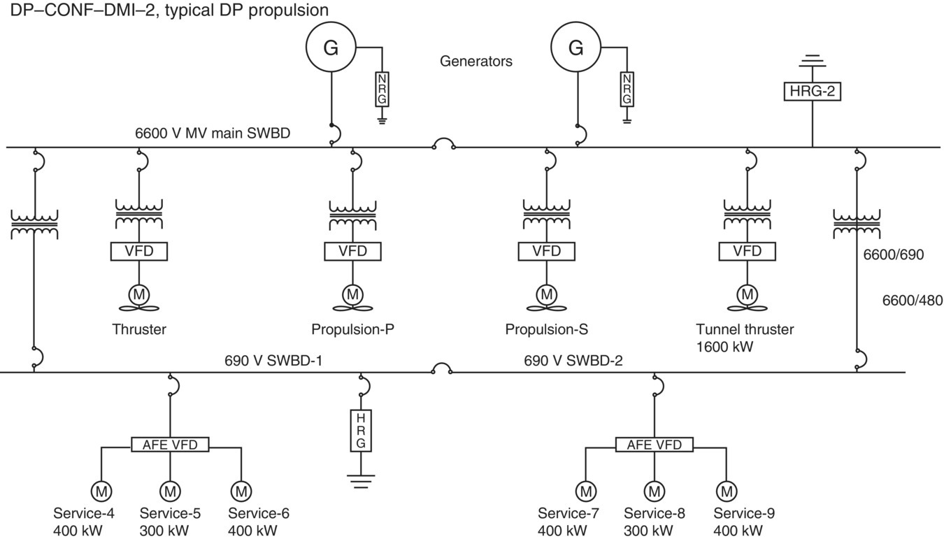
Figure 2.3 Typical DP ASD Propulsion, Thrusters, and VFD Drive Services.
Port—Ship service switchboard—480 V section
- Generator breakers
- Motor controllers
- Ship service load section for machinery auxiliaries, HVAC, deck machinery, and electrical services
- Shore power (open option of feeding from ship service or emergency switchboard)
- Emergency bus tie
Starboard—Ship service switchboard—480 V section
- Generator breakers
- Motor controllers
- Ship service load section for propulsion auxiliaries, HVAC, deck machinery, and electrical services
- Shore power (open option of feeding from ship service or emergency switchboard)
- Emergency bus tie
Starboard—Ship service switchboard—120 V section
- 115 V lighting
- Other 115 V services
2.4 Typical DP ASD Propulsion, and Thrusters All With VFD Drives (Figure 2.3)
In this example, there are four ship service generators, two ship service switchboards, one emergency generator, and one emergency switchboard. Each ship service switchboard is connected to two ship service generators. This set‐up is for ships with large service load demand, such as cruise ships. Due to the number of generators, the load distribution and management of four ship service generators and one emergency generator can be complex. However, the design has proven to be very successful. The parallel operation and necessary protective control and their interlocking must however be clearly understood by the operator.
There are four ship service generators, two ship service switchboards, one emergency generator, and one emergency switchboard. Each ship service switchboard is connected to two ship service generators. This set‐up is for ships with a large service load demand, such as cruise ships. Due to the number of generators, the load distribution and management of four ship service generators and one emergency generator can be complex. However, the design has proven to be very successful. The parallel operation and necessary protective control and their interlocking must however be clearly understood by the operator.
Port—Ship service switchboard—480 V section
- Generator breakers
- Motor controllers
- Ship service load section for machinery auxiliaries, HVAC, deck machinery, and electrical services
- Shore power (open option of feeding from ship service or emergency switchboard)
- Emergency bus tie
Starboard—Ship service switchboard—480 V section
- Generator breakers
- Motor controllers
- Ship service load section for propulsion auxiliaries, HVAC, deck machinery, and electrical services
- Shore power (open option of feeding from ship service or emergency switchboard)
- Emergency bus tie
