Chapter 8
Delivering Services
Now that you have a vCloud Director management pod, this chapter focuses on how you, as the system administrator, use that environment to build service offerings ready for your consumers to use.
We will cover the steps you'll take to create Provider Virtual Data Center (PvDC) to deliver tiers of service. You'll define organizations within your vCloud Director platform and nominate administrators for the various organizations. You'll create Organization vDCs (Org vDCs), which are allocations of resources from PvDCs, each with its own model for resource allocation and connections to various logical cloud networks.
In this chapter, you will learn to:
- Create PvDCs
- Create organizations and configure LDAP authentication
- Allocate resources to an organization
- Connect an organization to the corporate datacenter network
- Create and publish a basic service catalog to other organizations
Laying the Foundation: Building the Resource Pod
You will first explore the steps required to add the first vCenter server and the set of clusters that it controls. These will become PvDCs in vCloud Director, and from there you'll build Org vDCs.
You need to provide vCloud Director with at least one PvDC, which it will use to host Org vDCs. This chapter assumes that you have one or more vSphere clusters ready to use as PvDCs with vCloud Director, as described in Chapter 5, “Platform Design for vCloud Director,” and that you have deployed a vCNS Manager appliance in your management pod for the resource pod vCenter, as described in Chapter 7, “Installing VMware vCloud Director.”
A PvDC typically maps 1 to 1 with a vSphere cluster. Each cluster is differentiated by the tiers of service they are able to offer. For example, you may have a cluster that offers a gold-level service level agreement (SLA), with fast disks and redundant hardware. You may also have a lower-tier SLA cluster that offers slower disks and less resilient hardware or clusters that provide specific business or security-driven functionality such as encryption or increased security and auditing.
It is technically possible to map PvDCs to resource pools at the vSphere level. However, we strongly discourage you from doing so unless you have a comprehensive understanding of vSphere resource pools and a well-thought-out design. Such an approach can compromise vCloud Director's ability to effectively control the levels of resource allocation if they are not carefully implemented. This is especially true if you are planning to mix allocation models in a single PvDC; it limits vCloud Director's control of physical resource utilization because the various resource settings deployed by each allocation model can overlap. If you are considering this use case, check out the VMware white paper illustrating the impact of these scenarios here:
http://www.vmware.com/files/pdf/techpaper/vCloud_Director_Resource_Allocation-USLET.pdf
Building an Example Resource Pod
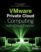
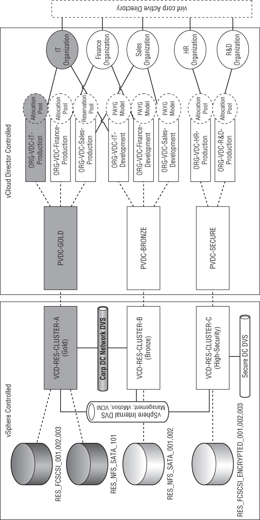
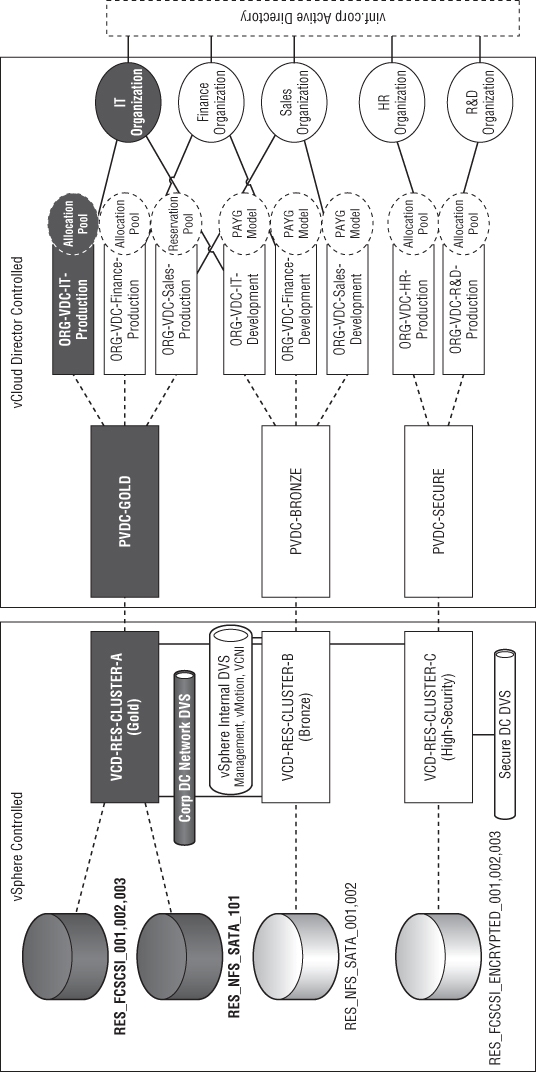
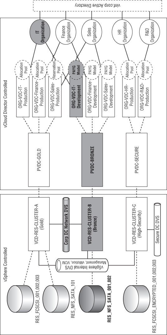
In this section, you will build on the management pod you created in Chapter 7 by adding an example resource pod design. The goal is to build a private cloud like that shown in Figure 8.1. The Human Resources (HR) and Research and Development (R&D) departments in this organization are bound by a security and regulatory policy that dictates they have a separate set of physical hosts, storage, and networks for their workload with specific security policy settings.
Figure 8.1 Mapping physical infrastructure to logical service tiers and organizational entities
The IT, finance, and sales organizations can share common computing, storage, and network infrastructure. They can choose from two service tiers: Bronze and Silver. The R&D and HR organizations can consume resources from a single secure service tier.
The sales organization has a data analytics application that requires 100 percent dedicated performance at all times. Therefore, their production Org vDC is configured with the Reservation Pool allocation model to ensure they always have dedicated computing resources available.
In terms of the vSphere configuration, each cluster has a specific host profile attached to it. This host profile ensures that the appropriate storage is mounted on each host and is consistent across the cluster.
Each datastore has a set of defined capabilities that are mapped into storage profiles. In this example you will use user-defined capabilities, but if you have a storage array that supports the vSphere API for Array Integration (VAAI) and vStorage APIs for Storage Awareness (VASA) extensions, then you can also create storage profiles based on attributes they expose.
Each cluster is configured in a specific manner to deliver three service tiers to our consumers in vINF Enterprises, our example company:
Gold
Provides a “gold” level 99.9 percent service to our consumers, with DRS and HA functionality and N+1 resilience. It only uses Tier 1 disk storage but offers Tier 3 disk storage for temporary storage.
Bronze
Provides a “bronze” level service, using only DRS functionality on the physical cluster and offering N+0 resilience (which means that in the event of a hardware failure, the hardware will be oversubscribed). Only Tier 3 disk storage (SATA) is available to this cluster.
High-Security
Provides a physically separate set of storage, computing, and network resources to meet a regulatory constraint and has array-level storage encryption to protect virtual machines (VMs). This solution is still able to be administered by vCloud Director administrators and uses a common vCloud infrastructure, but consumer workloads can run only within an isolated set of infrastructure within this cluster.
This high-security example is provided to illustrate a non-performance-driven capability provided by the underlying storage and computing infrastructure. Neither vSphere nor vCloud provides native filesystem encryption or other types of security enforcement. In this example, you should assume that this storage is supplied by a physically separate storage array that provides such functionality at the hardware level.
Each cluster is connected to a management network on a distributed virtual switch (DVS) that supports management traffic like vCenter, SSH, and vMotion. To support VM workload traffic, each cluster is connected to either the corporate datacenter network or a high-security network. Both networks are connected by means of a DVS and dedicated uplinks to the physical network on each vSphere host.
The logical diagram shown in Figure 8.1 represents a series of PvDCs that are created and mapped to vSphere clusters. For example, the VCD-RES-CLUSTER-A (Gold) cluster provides resources for the PvDC-Gold PvDC.
Each PvDC provides resources to one or more Org vDCs. Each Org vDC has an allocation model that is one of the following types:
- Allocation Pool
- Pay-As-You-Go
- Reservation Pool
Each Org vDC is “owned” by an organization, which is an administrative and authentication boundary for a department or business unit within your private cloud. Each Org vDC has an associated authentication source—in this case, the vinf.corp Active Directory.
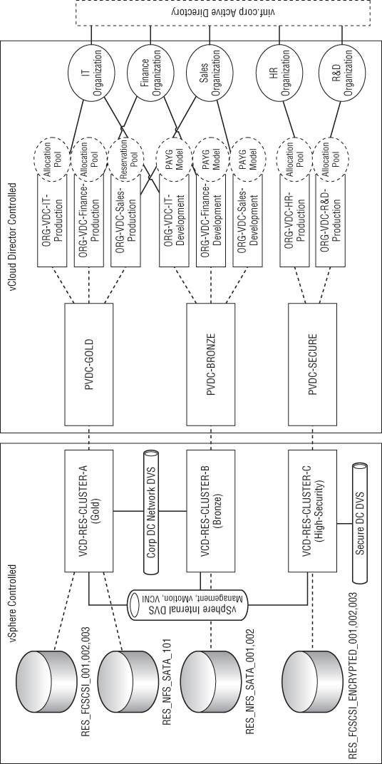
Figure 8.2 shows that the VCD-MGT-VC03 server is a dedicated vCenter for Resource Pod A. Resource Pod A is a logical grouping of vSphere clusters managed by a single vCenter server. Each service tier maps to a vSphere cluster, and each vSphere cluster has access to different sets of physical infrastructure (storage, networks) and logical configuration (DRS/HA) to build up the service offering.
Figure 8.2 Resource pod design for vINF Enterprises Inc.
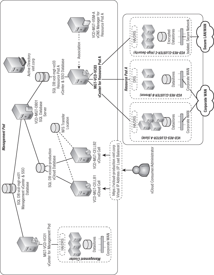
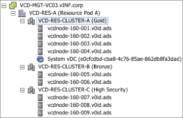
At a physical level we have three clusters configured and ready to use in this resource pod. Figure 8.3 shows a view of the clusters from the vSphere client.
Figure 8.3 vSphere client view of resource pod containing three clusters ready for consumption by vCloud Director
Associating vCNS Manager with Your Resource Pod
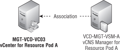
In Chapter 2, “Developing Your Strategy,” you deployed a vCNS Manager appliance in the management pod, VCD-MGT-VSM-A. You must associate this appliance with the resource pod you are building by connecting it to the vCenter server, as shown in Figure 8.4.
Figure 8.4 The relationship between vCNS Manager and vCenter within a resource pod
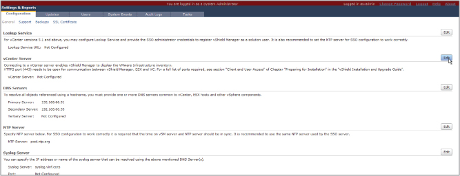
This is a simple process; you use a web browser to connect to the web server running on the vCNS Manager appliance and log on using the credentials you set in Chapter 7. Click on the Settings & Reports item in the left-hand navigation tree; then use the interface shown in Figure 8.5 to complete the association with vCenter Server.
Figure 8.5 vCNS Manager interface accessed by web browser
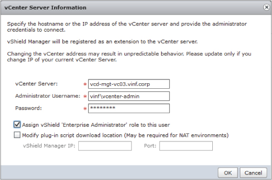
Enter credentials for your vCenter server, as shown in Figure 8.6, by clicking the Edit button next to the vCenter Server entry.
Figure 8.6 vCNS Manager credentials to attach to vCenter Server
You may get a warning about an unrecognized thumbprint. Choose to import it, and when it's completed you'll see that vCNS Manager can connect and inventory the vCenter server, as shown in Figure 8.7.
Figure 8.7 vCNS Manager connected to vCenter

If you get an error, you should verify name resolution between your vCNS Manager appliance and your vCenter. You can log on to the console of the vCNS Manager from the vSphere client and access the basic tools (like ping) that are available in its console.
Licensing vCloud Networking and Security
vCNS has its own license. You need to license it before you can use it fully. By default, vCNS installs using an evaluation license that expires approximately 90 days from installation.
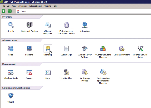
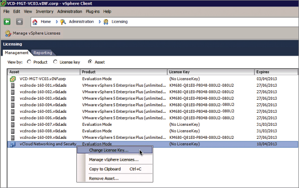
You configure this license using the vSphere client. To begin, connect to the vCenter server that you set up in the previous section. On the Home screen, click Licensing, as shown in Figure 8.8.
Figure 8.8 Click Licensing
Locate the vCloud Networking And Security entry in the asset list. Right-click and choose Change License Key, as shown in Figure 8.9.
Figure 8.9 Choose Change License Key
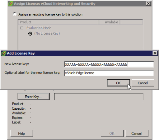
Choose Assign A New License Key To This Solution and enter your license key, as shown in Figure 8.10.
Figure 8.10 Entering a license key for vCNS Manager
Once you complete these steps, your vCNS solution is licensed.
Configuring LDAP Authentication
Before your consumers can use LDAP authentication in your vCloud, you need to configure vCloud Director to communicate with your corporate Active Directory (or other LDAP-based directory).
If you want any of your consumers to be able to use LDAP or to authenticate to a separate Active Directory, you'll also need to configure the system with a default LDAP server. Your consumers can later override this setting to use their own server when they configure their Org vDCs.
This is a simple process and it's done from the Administration tab of the vCloud Director interface. If you click on LDAP, you can enter the name of a single domain controller you want to communicate with for authentication.
As shown in Figure 8.11, you can specify the base distinguished name for your directory. In this example you are connecting to your corporate Active Directory (vinf.corp) by specifying dc=vinf,dc=corp. You need to enter a user account and a static password. This user can be a standard user account; it does not require administrative access as it simply queries Active Directory for account names to authenticate against rather than requiring any write permissions.
Figure 8.11 Configuring LDAP server details
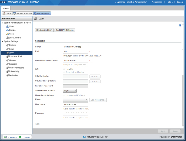
Click the Test LDAP Settings button to search for a user account and validate that the communications are successful.
In our example organization, there is a group in Active Directory called vCloudAdministrators. This means vinf.corp users can log on to vCloud Director using their Active Directory account to administer vCloud. This approach is desirable for larger environments and to ensure there is an audit trail to changes made.
To allow an Active Directory (or any LDAP source) group access to vCloud Director, navigate to the Groups section of the vCloud Director interface under the Administration tab, as shown in Figure 8.12.
Figure 8.12 Importing groups from an LDAP source
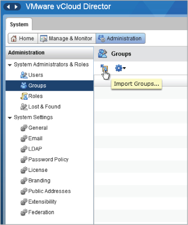
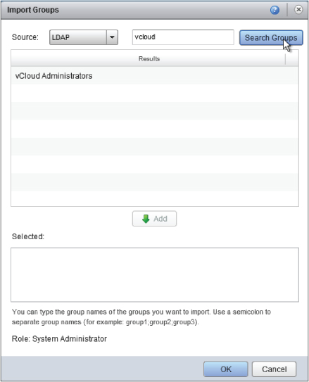
Click the Import Groups button and enter a search string (in this case, vcloud). You will see a list of matching groups from your LDAP source. You want to make the vCloud Administrators Active Directory group a member of the vCloud system administrator role, so click Add and then click OK to make the change (Figure 8.13).
Figure 8.13 Selecting an LDAP group from a search
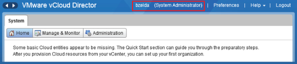
All members of the vCloud Administrators Active Directory group can now log on to the vCloud Director interface using their Active Directory credentials, as shown at the top of Figure 8.14.
Figure 8.14 Logged on using LDAP credentials
Setting the SMTP Server
vCloud Director can use an SMTP server to send notifications to administrators and consumers. You can configure this on the Administration tab of the vCloud Director interface. Under System Settings click Email to see the options shown in Figure 8.15.
Figure 8.15 SMTP server settings
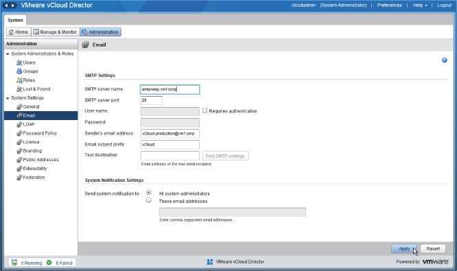
As with the LDAP configuration, bear in mind that the communication is initiated from the cell server(s), so your network should allow SMTP traffic (port 25, TCP) from the cell server to your SMTP relay. If your SMTP relay requires authentication, you can specify it on this page. When you create organizations, they have the option of using the system default SMTP server or specifying their own. Again, if you have a segregated environment, your consumers will need to ensure that their own SMTP relay server can receive SMTP traffic from the cell servers and that appropriate authentication is configured on both sides.
Attaching a vCenter Server to Your Resource Pod
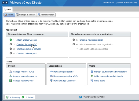
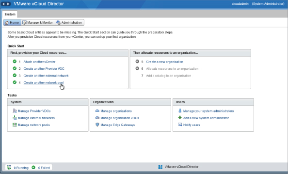
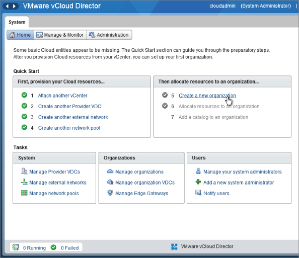
When you log on to vCloud Director as the cloud administrator account (cloudadmin) that you created in Chapter 7, you'll see a familiar wizard/checklist type interface, as shown in Figure 8.16.
Figure 8.16 Logging on to vCloud Director
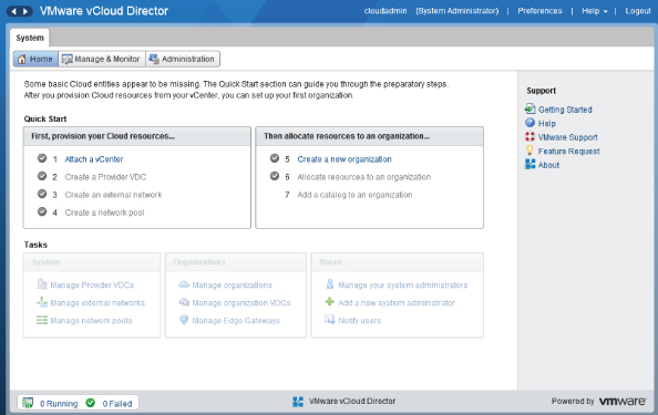
You'll notice that the wizard shows the next required step as a clickable option. The steps you cannot yet complete because they are dependent on the first are grayed out.
The first task is Attach A vCenter. Click the link and you are prompted for the details of the vCenter server you are connecting to. Enter the details of VCD-MGT-VC03, which will be controlling Resource Pod A and the three initial clusters that it contains, as shown in Figure 8.17.
Figure 8.17 Attaching a vCenter server to vCloud Director to create the first resource pod
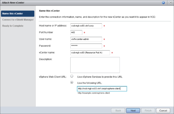
The account you specify must have administrative permissions to the vCenter server. You can enter the vSphere web client URL manually. This allows administrators to right-click objects in the vCloud Director interface and browse to the underlying object in the vSphere web client if you have it installed on your vCenter server.
Click Next and you'll be prompted for vCNS Manager connection details, as shown in Figure 8.18.
Figure 8.18 Entering credentials to connect to vCNS Manager
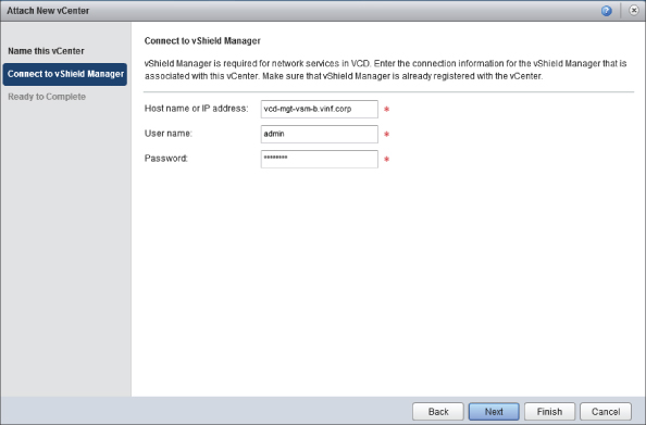
You'll recall that you associate one vCNS Manager with every vCenter you deploy as part of a resource pod in your cloud. In this case you are going to associate your resource pod with VCD-MGT-VSM-B and provide the FQDN and credentials to connect to it.
If you have to change the vCNS Manager password after making this connection, you can edit the password within vCloud Director and reconnect it.
Your resource pod is now ready to be mapped to PvDCs in vCloud Director.
Creating PvDCs
In this step you will be creating the Gold PvDC for our example deployment. This configuration is carried out from within vCloud Director, and assuming your vSphere layer has been appropriatley prepared with storage profiles and clusters, you do not have to configure anything else in vCenter.
Figure 8.19 shows that the Gold PvDC is made up of specific storage (as grouped together via a storage profile), a cluster, and an external network. In the following steps you'll group all these resources together into the first PvDC.
Figure 8.19 Resources mapped to the Gold PvDC
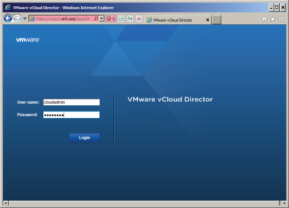
Connect to your vCloud Director interface—in this example, https://vcloud.vinf.corp. You'll notice that the root URL automatically redirects you to /cloud/; this is the logon page for cloud administrators.
Log on using the cloudadmin account that was created when you installed vCloud Director, as shown in Figure 8.20. Only the system administrator can create PvDCs.
Figure 8.20 Logging on as the system administrator (cloudadmin)
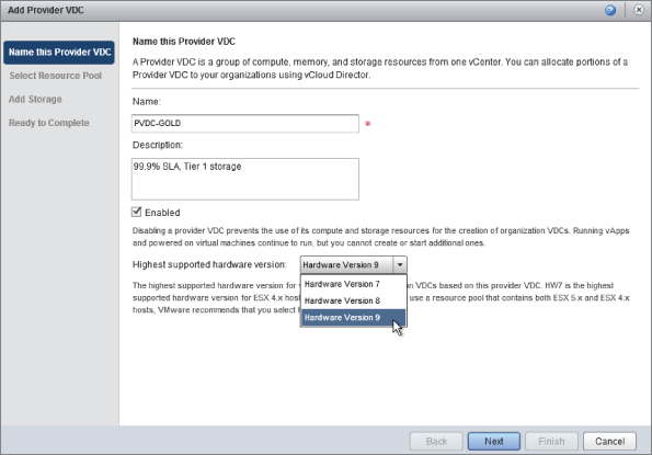
As shown in Figure 8.21, click Create A Provider VDC. A wizard launches that lets you create a PvDC. Enter descriptive information about the PvDC you are creating. In this example, you will be creating a PvDC that is capable of delivering a Gold level of service.
Figure 8.21 Click Create A Provider VDC to launch the wizard
The description field can be used to give the consumer and organization administrators a better idea of what facilities are available. In this case, the Gold PvDC consists of a cluster with N+1 resilience and is built on Tier 1 15K Fibre Channel SCSI storage. As such, this is a tier of service that may be well suited to production or high-performance activites in your organization.
You'll notice in Figure 8.22 that you can set the highest supported hardware version. This is an important consideration if you have a platform that mixes older versions of vSphere like 4.x in a cluster with 5.x hosts, which do not support Hardware Version 8. Mixing host versions in a cluster is not generally a good practice, but you may find yourself in this situation if you are in the process of a version upgrade. In this example, our hosts are all running vSphere 5.1, so you can support the latest virtual hardware version (which is 9).
Figure 8.22 Naming the PvCD and examining supported virtual hardware versions
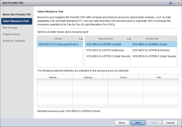
The wizard asks you to select a resource pool, as shown in Figure 8.23. For our example, choose a cluster from our vCenter called VCD-RES-CLUSTER-A (Gold). Doing so allocates the resources of the entire cluster to the Gold Provider vDC you are creating, and as such you will not be able to create any further provider vDCs that use the resources from this cluster. This step allocates the cluster as a resource available to vCloud Director and will make it unavailable for any other PvDCs.
Figure 8.23 Select Resource Pool page
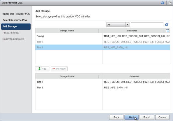
As shown in Figure 8.24, you are prompted to choose the storage profiles that are availabe to this PvDC. For this example you are presenting two tiers of storage to the Gold PvDC, Tier 1 and Tier 3. Select each storage profile and click Add.
Figure 8.24 Selecting storage profiles for our PvDC
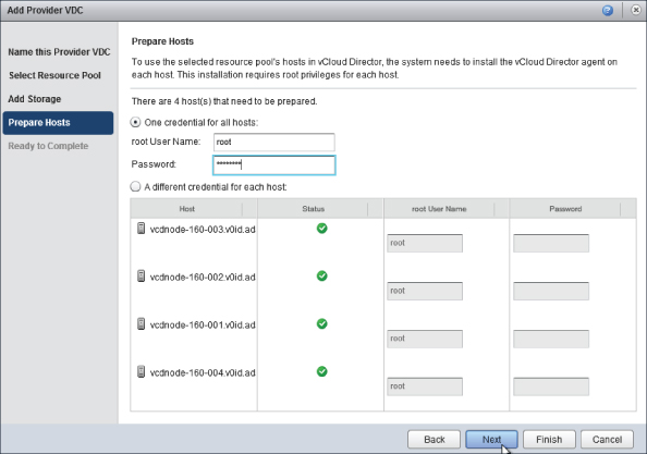
vCloud Director needs to install its agent to a host to enable it to function with vCloud Director, and you must provide root credentials for each host. As shown in Figure 8.25, if you have the same root credentials for each host, you can choose to use one set of credentials or enter a password individually for each host.
Figure 8.25 Providing credentials on the Prepare Hosts page
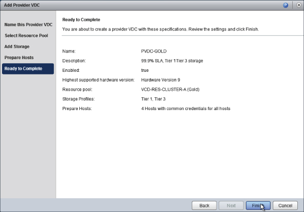
You are shown a summary screen (see Figure 8.26). This page summarizes the details you have just entered. Click Finish to complete the wizard and create the PvDC.
Figure 8.26 Summary screen
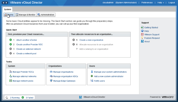
You can check the status of the PvDC creation by clicking at the bottom left of the screen, where in Figure 8.27 it says “2 Running.” This will show you the status of the agent installation task(s). This task will automatically put each vSphere host into Maintenance Mode, install the agent, and then exit Maintenance Mode. This process does not require a reboot of each host or any manual intervention.
Figure 8.27 Host preparation job progress screen
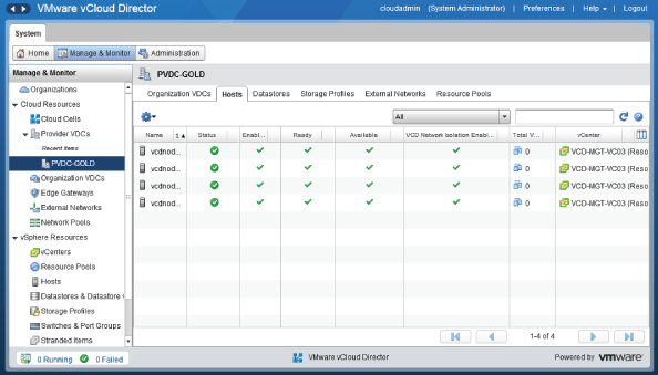
You can verify that the task has completed sucessfully by selecting the Manage & Monitor tab at the top of the vCloud Director interface and then clicking in the Provider vDCs section and selecting the PvDC. You should see your hosts on the Hosts tab, as shown in Figure 8.28. A green check mark indicates they are ready for use. Any errors will be flagged by a red circle with a line through it. You can click on each for troubleshooting details.
Figure 8.28 Hosts prepared and ready for use with vCloud Director
Once the task has completed successfully, you'll notice that you have a new System vDC object created in vCenter, as shown in Figure 8.29. This demonstrates that vCloud Director is in control of the vSphere cluster, and it will use this newly created resource pool to house system resources like vCNS Edge appliances.
Figure 8.29 vSphere objects created by vCloud Director
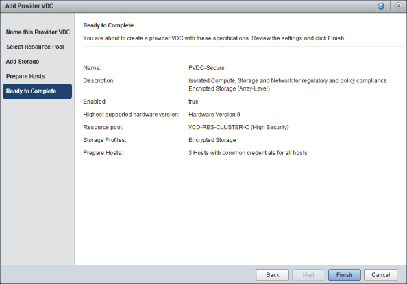
You now have created your first PvDC. The process is the same for the remaining PvDCs in our example (PvDC-Bronze and PvDC-Secure); you select different clusters and storage profiles when prompted. Figure 8.30 shows the settings applied to the PvDC-Secure PvDC.
Figure 8.30 Creation of the PvDC-Secure PvDC
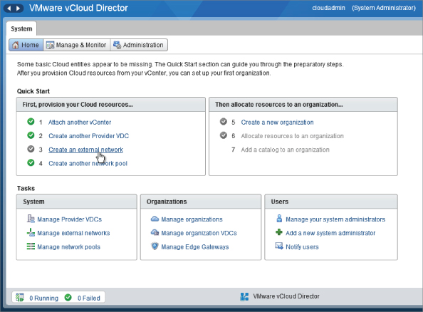
Creating an External Network
Now that you've created your first PvDC, you'll notice that the wizard on the home page changes. The next step is to allocate an external network to your PvDC. You should think of an external network as a datacenter network. There may be several available for PvDCs within a resource pod to connect to. In most private cloud deployments, the external network will be one or more physical datacenter VLANs and associated IP subnets that are accessible from the corporate datacenter LAN and then out to the corporate WAN (depending on your network topology).
The external network acts as an interchange point of traffic between organization and internal networks. This is where vCNS Edge plays an important role by providing Network Address Translation (NAT) for organization networks to do the following:
- Reduce the number of IP addresses required in the corporate datacenter
- Allow fencing to support creation of multiple instances of the same vApp and IP address ranges
In this example, you will create an external network to represent our corporate datacenter network, which you can use to allow organizations running services in the Gold and Bronze PvDCs to connect to the corporate network. Click Create An External Network to begin the process (Figure 8.31).
Figure 8.31 Click Create An External Network
You will see the wizard shown in Figure 8.32. Select the vCenter controlling this resource pod—in this instance, VCD-MGT-VC03, which is controlling Resource Pod A. You are going to add the CorpDatacenterNetwork to our cloud to allow our consumers to make connections to the corporate network.
As shown in Figure 8.32, vCloud Director automatically detects that PvDC-Gold and PvDC-Bronze have access to it. vCloud Director knows this because if you refer to Figure 8.1 only those clusters are attached to the CorpDatacenterNetwork distributed virtual switch (DVS).
Likewise, as Figure 8.33 shows, the HighSecurityNetwork is only available to the secure PvDC because the vSphere cluster underpinning PvDC-Secure is the only one attached to the HighSecurityNetwork DVS.
The external network that is attached to it is shown. In this simple example the VM Network vSphere network is a port group with access to the corporate datacenter LAN.
On the next step in the wizard, shown in Figure 8.34, click Add to add a subnet to this external network. You should think of this as entering the subnet details that have been allocated to you by your corporate datacenter network administrators. In this example you have been allocated 75 IP addresses from the datacenter range of 192.168.66.0/24. Each device that is connected to the external network—for example, a vCNS Edge appliance—will be allocated an IP address from this static IP pool.
Figure 8.32 External networks available from Gold and Bronze PvDCs
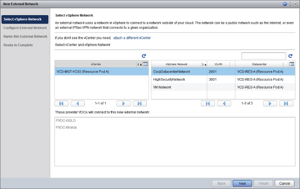
Figure 8.33 Differences in available external networks between PvDCs due to different underlying vSphere configurations
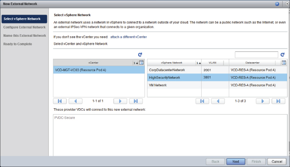
Figure 8.34 Entering IP subnet details for our external network
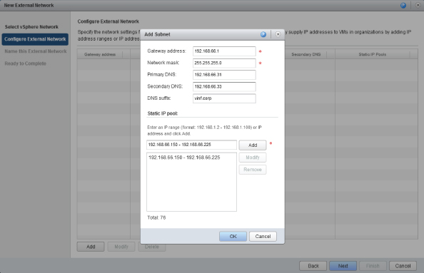
vCloud Director uses this information to act as an IP address management tool for the virtual networks you define. But it's not only capable of allocating IP addresses from the static IP pool; it can also configure vApps under its control with the relevant IP address information from this pool. This is the reason you specify DNS server and suffix details as they are automatically configured inside the VM by vCloud Director if you enable guest customization.
You'll be asked to give the network a name; then you are shown a summary screen (Figure 8.35). Click Finish to complete the wizard and create the external network.
Figure 8.35 Ready to create an external network to connect to the corporate datacenter network
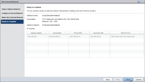
Your resource pod now has a logical connection to the corporate datacenter network with a pool of 75 IP addresses from the 192.168.66.0/24 range. This connection is available to the PvDC-Gold and PvDC-Bronze PvDCs you created earlier.
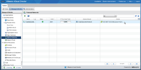
If you navigate to the Manage & Monitor tab of the vCloud Director interface, as shown in Figure 8.36, and look under Cloud Resources at External Networks, you'll see the external network object. You can see that it has picked up the VLAN ID associated with this vSphere network (2001). You can also see the percentage of IP addresses in use from the pool of 75 IP addresses that we defined in the previous step.
Figure 8.36 External network showing the IP address pool
Creating a Network Pool
Now that you have defined an external network, you'll need to create a network pool. You'll create a pool of virtual networks that can be created and deleted on demand by vCloud Director for networks required to support vApp and organization networks.
On the Home screen, click the Create Another Network Pool task, as shown in Figure 8.37. In this example environment, previous network pools have been created prior to this step.
Figure 8.37 Click the Create Another Network Pool task
You need to specify how the network pool will be created on the vSphere layer. For the most appropriate choice here, refer to Chapter 5 for the various options and criteria. The three options are shown in Figure 8.38.
Figure 8.38 Network pool types
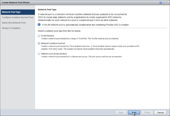
In this example, you are going to create a vCloud Director Network Isolation (VCNI)-backed network pool, a pool of virtualized and isolated Layer 2 networks that are encapsulated inside a physical transport VLAN between vSphere hosts in your PvDCs.
You will need a dvSwitch to use this setting. In our example resource pod shown in Figure 8.1, you have all the vSphere internal communications (HA, vCenter, vMotion traffic, etc.) going through a separate DVS with its own physical uplinks called vSphereInternal.
You'll create a pool of 500 vCloud Director networks, all of which will be encapsulated inside a single physical VLAN. You'll recall from Chapter 5 that this process has some physical network requirements. You must increase the MTU size for all uplink ports attached to the vSphereInternal DVS and ensure that the transport VLAN you specify in Figure 8.39 is valid and configured on the physical switch interfaces to all hosts in your cluster. Otherwise, cross-host communications using VCNI will fail.
You'll appreciate that the ability to create 500 (and up to 1000 per VCNI pool) isolated Layer 2 networks, and only having to ask your networks team for a single physical VLAN is a powerful feature.
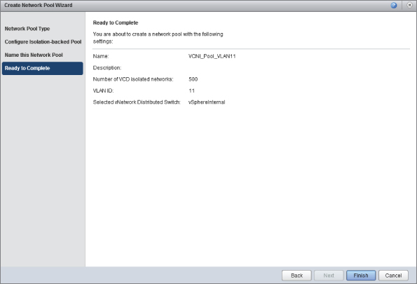
You're asked to give the network pool a name. To simplify troubleshooting and maintenance, it's advisable to specify the VLAN ID in the name. Click Next and you are shown a summary screen (Figure 8.40). Click Finish to complete the wizard.
Now this task is complete. You'll see that the first part of the wizard is done. You now have a single PvDC with a connection to the corporate datacenter network, as well as a pool of virtual networks ready to be allocated.
Figure 8.39 Configuring the quantity of vCloud isolated networks and specifying the transport VLAN ID
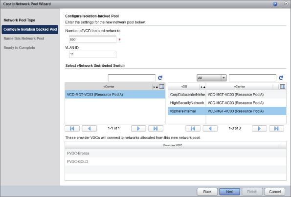
Figure 8.40 Creating VCNI network pool summary screen
Creating an Organization
In a private cloud setting, an organization is likely to map to a business unit, department, or division. Each organization has its own suballocation of resources from one or more PvDCs, which are known as Org vDCs.
An organization is an authentication boundary for your consumers. Each organization can have individual settings for authentication and authorization.
In addition to providing a standalone list of users, an organization in vCloud Director can be configured to integrate with an LDAP directory like Microsoft Active Directory to use a common authentication source for your consumers. You cannot create a hierarchy of organizations in vCloud Director—they are all equal—but you can apply roles and permissions to user accounts and groups associated with an organization.
Only the system administrator can create organizations, but during creation a user is nominated to be the administrator of each organization (known as an organization administrator). They can subsequently create further user accounts or reconfigure authentication.
In this example, you'll create an organization called IT. It will own and share various template and master image vApps for other organizations to consume as well as run its own production vApps. You can create this organization from the Home screen on the vCloud Director interface, as shown in Figure 8.41.
Figure 8.41 Choose Create A New Organization
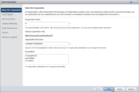
When prompted, enter some descriptive information for your new organization. You cannot use a space or nonalphanumeric character in the organization name, but you can in the organization full name (which equates to a display name).
Some security-conscious organizations prefer to specify a number or something that isn't obviously guessable for the organization name. This would result in an ambiguous URL like https://vcloud.vinf.net/cloud/org/9022145X. As there is no way of obtaining a master list of configured organizations available unless you are logged on as a system administrator, this makes it harder for attackers to guess default logon URLs.
Naming the department IT results in the settings shown in Figure 8.42. Click Next to continue.
Figure 8.42 Naming an organization
In this example, you'll point this organization at Active Directory for authentication and provide a distinguished name (DN) that maps to an OU in the vinf.corp Active Directory, as shown in Figure 8.43.
Figure 8.43 Object location in Active Directory
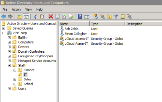
You'll recall that you configured the system LDAP service to point at the vinf.corp Active Directory. You now need to specify which organizational unit (OU) in the directory contains users and groups that are associated with this new vCloud organization. In this example, you specify the DN of the IT OU in Active Directory, as shown in Figure 8.44.
Figure 8.44 Configuring LDAP options
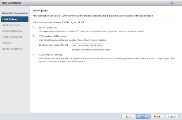
You are advised to create at least one local user. In practice this is a private cloud implementation and isn't generally required. The system administrator will still be able to log on if Active Directory is unavailable and so could potentially override such settings if required due to a long-term Active Directory failure. Therefore, you can skip this step.
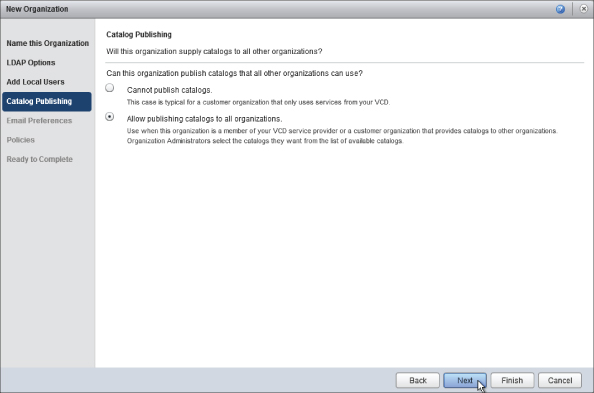
In our example organization, the IT department will be providing standard operating system install media and VM builds for use by consumers. So you can select the Allow Publishing Catalogs To All Organizations option, as shown in Figure 8.45. For most other organizations in our private cloud, this isn't likely to be required and can be left at the default; the setting can be changed by the system administrator if required at a later date.
Figure 8.45 Catalog publishing options for a new organization
You next see a set of email preferences, as shown in Figure 8.46. Enter SMTP server details for email notifications from vCloud Director if they differ from the system settings, but bear in mind that the communication is initiated from the vCloud Director cell servers to the SMTP relay you specify. That means you need to ensure there is a network path through any firewalls or routers and that authentication is correctly configured on both ends.
Figure 8.46 Setting email preferences
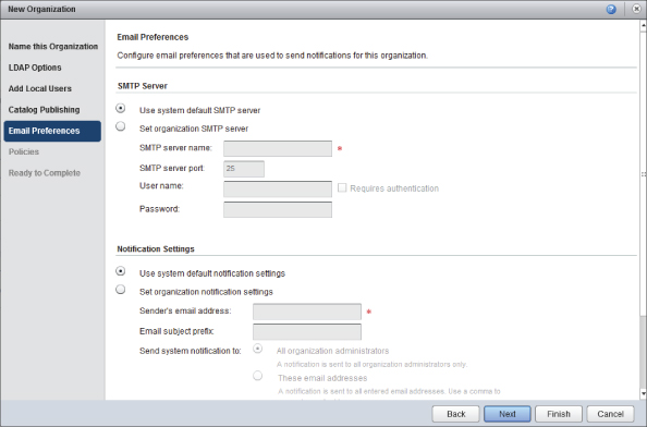
In this example, the IT department is part of the vinf.corp Active Directory, so you will use the system default SMTP server, which will accept email for @vinf.corp email addresses.
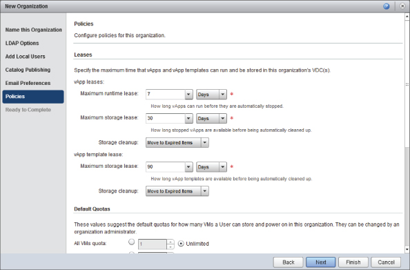
Next, you are prompted to set policy information for the organization that you are creating, relating to how long consumers within this organization are allowed to consume resources. This is known as a lease.
You can set appropriate options for this organization by choosing from the list. The system defaults are sensible for most use cases (Figure 8.47).
Figure 8.47 Specifying policies for the new organization
A number of policy settings are available on a per-user basis. You'll typically have to scroll down to see all of them, as shown in Figure 8.48.
Figure 8.48 Organization policies: quotas and limits
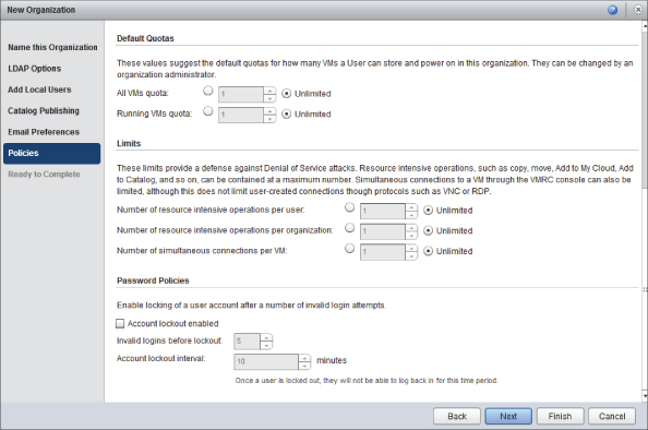
Although leases control the duration for which resources can be consumed, quotas and limits are useful settings to control the amount of resources individual consumers can use at a given point in time.
The password policies apply only to vCloud Director authentication. If you are using an external LDAP source, the settings should be those enforced by the external LDAP source.
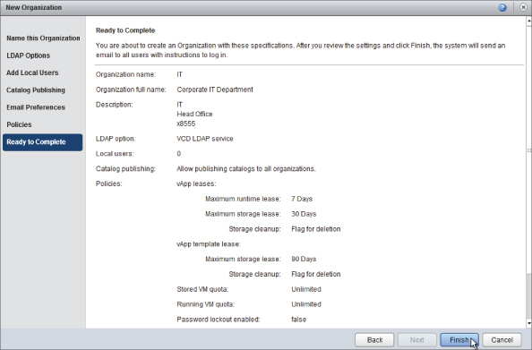
You are shown a summary screen (Figure 8.49). Once you click Finish, the organization will be created and ready for use.
Figure 8.49 You're ready to create the IT organization
Once the organization is created in this way, only the system administrator will be able to log on. Although the LDAP source was configured, the wizard does not allow any users to use vCloud Director by default. To allow this, you must navigate to the organization in the vCloud Director interface by clicking Manage Organizations on the Home screen or by using the Manage & Monitor tab and selecting Organizations.
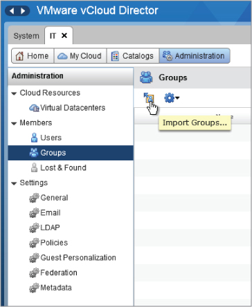
Once you have opened the IT organization (as denoted by the new IT tab at the top of the screen), navigate to Members, select Groups, and then click Import Groups, as shown in Figure 8.50.
Figure 8.50 Importing an LDAP group to an organization after creation
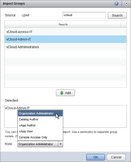
In this example, you'll enable a group called vCloud-admin-IT for organization administrators in vCloud, as shown in Figure 8.51.
Figure 8.51 Importing an LDAP group for an organization
Using groups is the most efficient approach for managing access to vCloud resources. As part of normal Active Directory management, you can add and remove users from groups, rather than directly configuring vCloud Director.
You can follow the same process to enable other users and groups to use this vCloud organization.
Creating an Organization Virtual Datacenter
Each organization is configured with one or more Org vDCs. Each Org vDC has an allocation model, which determines how it can consume resources from the underlying PvDCs it is configured to use.
In this example, you're going to create the first of several Org vDCs to represent different levels of service that you are making available to each organization in our example vCloud implementation.
Production
Resources in the Gold service tier are consumed and allocated using the Allocation Pool model within vCloud Director. Each Org vDC is given a fixed allocation of CPU and memory with a minimum percentage of those resources being guaranteed. They have the ability to consume extra resources from the cluster up to the allocation if they are available (commonly known as bursting).
Development
Resources in the Bronze service tier are consumed on a Pay-As-You-Go allocation model. The primary use case here is test and development, so a low resource guarantee is given and resources are allocated on a first-come, first-served basis until they are exhausted or further capacity is added.
High-Security
Like the Gold service tier, the Secure service tier is intended for production services and is configured for the Allocation Pool model within vCloud Director, but it runs on isolated computing and network resources and dedicated storage with array-level encryption.
The sales organization is an exception to this convention and has a single Org vDC configured to use the reservation pool model for its production workload.
In the previous step, you created the first organization to represent the IT department, and you are ready to allocate resources to it. This allocation of resources creates the Org vDC. As shown in Figure 8.52, click Allocate Resources To An Organization.
Select the organization you are going to be adding resources to. In this example we have a single organization, IT, as shown in Figure 8.53.
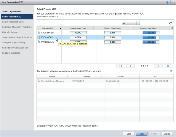
Figure 8.54 shows how you choose where these resources will be allocated from. In this example, you'll be allocating resources from the PvDC-Gold PvDC that we created earlier. Notice that if you hover your mouse over each PvDC you'll see a note showing the description of each PvDC as a reminder of what has been set.
Figure 8.52 Allocating resources
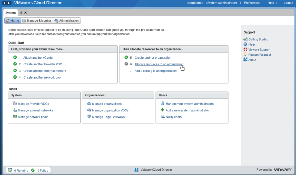
Figure 8.53 Choosing the organization
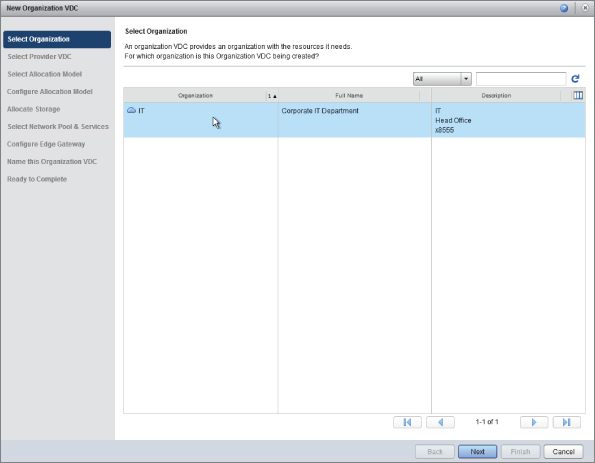
Figure 8.54 Selecting the PvDC to allocate resources from
Configuring the Resource Model
Each Org vDC that you deploy can be configured with one of three allocation models. Each allocation model determines how resources are allocated from the PvDC. Settings within an allocation model can be adjusted by the system administrator. An Org vDC cannot be changed to a different allocation model once the Org vDC has been created. If you need to change the model, the only option is to delete and re-create it.
Only the system administrator can configure the allocation model settings for an Org vDC. Organization administrators can only work with what they have been granted.
In the following examples you'll learn how to configure each of the three allocation models and Org vDCs. See the following mapping of resource models to the Org vDCs.
| Organization vDC | Allocation model in use |
| ORG-vDC-IT-Production | Allocation Pool |
| ORG-vDC-IT-Development | Pay-As-You-Go |
| ORG-vDC-Sales-Production | Reservation Pool |
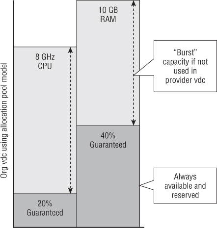
The overall service level on offer to consumers is determined by the PvDC, which defines base performance, availability, and capacity characteristics, and by the Org vDC, which defines how much of that resource is guaranteed from the PvDC (see Figure 8.55).
Figure 8.55 How provider and Org vDCs define a service level to consumers
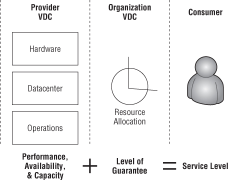
The allocation model you configure determines the level of resource oversubscription that will apply to vApps deployed into this Org vDC. As such, you are defining the last part of the performance service level for consumer vApps that are deployed into this Org vDC.
Configuring the Allocation Pool Model
In this example you'll deploy our PvDC using the Allocation Pool allocation model for the Org vDC called ORG-vDC-IT-Production. Your choice here will depend on your specific solution design and service offering.
Figure 8.56 shows the elements involved in building the ORG-vDC-IT-Production Org vDC. The Internal DVS is part of the back-end transport for VCNI and underlying cluster functionality like vMotion and management. Thus it is not specifically highlighted as part of Figure 8.56.
Figure 8.56 ORG-vDC-IT-Production elements
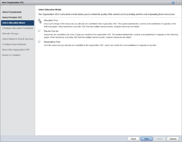
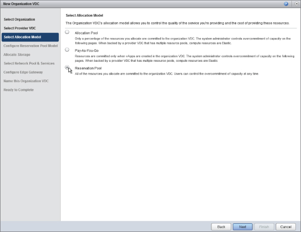
When prompted, choose the Allocation Pool allocation model, as shown in Figure 8.57.
Figure 8.57 Choosing an allocation model
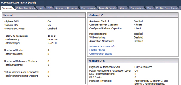
Use vSphere Client to look at the physical properties of the cluster that the PvDC-Gold object represents, as shown in Figure 8.58. Note that there are resources consisting of 16 GHz of CPU and 64 GB of RAM provided from four hosts that comprise the VCD-RES-CLUSTER-A (Gold) cluster in vSphere.
Figure 8.58 Physical properties of the cluster that backs PvDC-Gold PvDC: 16 GHz of CPU and 64 GB of RAM (1 failover host)
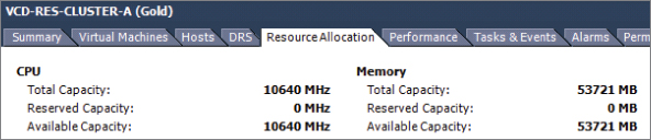
But on the Resource Allocation tab shown in Figure 8.59, you can see that slightly fewer resources are available to vCloud Director. This is because of the one dedicated failover (N+1) host setting that has been configured for HA in this cluster. This leaves fewer overall resources available for consumption.
Figure 8.59 Cluster resource allocation, factoring in HA overhead
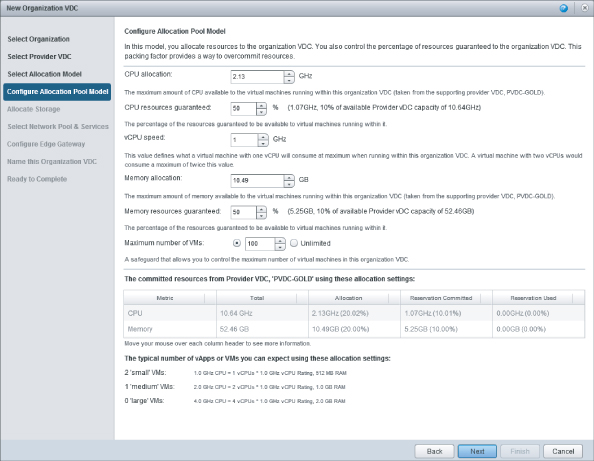
You are prompted to configure the Allocation Pool model for this Org vDC, as shown in Figure 8.60. The Allocation Pool model is most commonly found in production environments, where it provides a minimum guaranteed level of service with some “burst” capability.
Figure 8.60 Options available when configuring an Org vDC with the Allocation Pool model
In this example you have a small PvDC from which to allocate resources. The default options reserve a large amount of infrastructure.
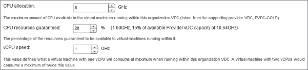
The CPU Allocation value specifies how many CPU resources (expressed in GHz) from the PvDC are to be allocated to this Org vDC.
In the example shown in Figure 8.61, you'll specify that you want to allocate 8 GHz for VMs to the IT department's Production Org vDC. The IT department needs only low-usage VMs for running domain controllers and DNS servers. You'll then define what percentage of this maximum CPU allocation is to be guaranteed to those VMs. Prior to vCloud Director 5.1 this percentage was the amount of CPU reserved on the resource pool. However, as of vCloud Director 5.1 that's no longer the case. The amount is still reserved on the resource pool, but it is calculated based on the VM vCPU Count, vCPU Speed, and Reservation settings. A cumulative total for all VMs is then used to define the resource pool reservation.
In this example, you know the IT department production workload is low usage, so you'll set a low resource guaranteee of 20 percent and define a vCPU speed of 1 GHz.
You'll notice that the dialog box automatically calculates how much physical resource this allocation will consume from the PvDC. You are going to allocate 15 percent of the overall available CPU capacity on the PvDC for this Org vDC, leaving 85 percent available for other Org vDCs or as capacity for the IT department to consume if needed.
Figure 8.61 CPU allocation settings
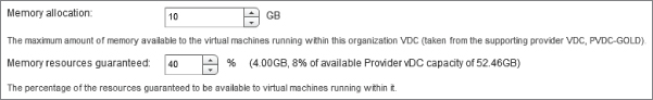
Likewise, in Figure 8.62 you set similar values for the Memory allocation in the IT department production Org vDC. You allocate the IT department a maximum “pool” of 10 GB of RAM for its VMs, but you guarantee that only 40 percent is allocated for its exclusive use.
Figure 8.62 Memory allocation values in an Org vDC
In the Allocation Pool model, everything over the guarantee values is unreserved capacity, which can be used to “burst” but is shared with other consumers. This allows you to provide a guaranteed minimum level of service in terms of memory availability while allowing consumers to use additional resources if they are available in the PvDC. This configuration results in an estimate at the bottom of the dialog box that shows how many typical vApps or VMs your consumers will be able to create inside this Org vDC (Figure 8.63).
Figure 8.63 Burst capacity provided in the Allocation Pool model
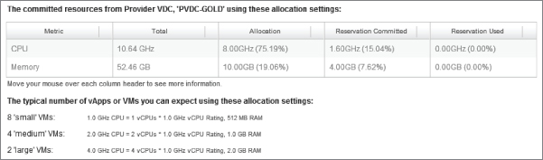
Note that from a total pool of 10.64 GHz of CPU and 52.46 GB of RAM, 8 GHz of CPU is allocated from the PvDC (which represents 75.19 percent of the overall physical capacity), but only 15.04 percent of that is reserved and thus guaranteed for consumers.
Likewise, you see that 19.06 percent of physical memory resources in the PvDC are allocated to this Org vDC, but only 4 GB (7.62 percent) of those physical resources are guaranteed.
Finally, Figure 8.64 shows that you can configure a maximum number of VMs that can be deployed into this Org vDC. This setting isn't commonly used in the Allocation Pool model; you are providing an allocation of resources for your consumers, and generally the amount of available resources is the controlling factor in determining how many VMs can be deployed. However, it may make sense to do so in other allocation models.
Figure 8.64 Controlling the maximum number of VMs allowed in an Org vDC

A summary (see Figure 8.65) is provided at the bottom of the page, which shows how many resources are allocated vs. the amount reserved for your consumer workloads. It provides an estimate of the number of typical vApps or VMs that you will be able to run within your Org vDC using the configured settings. These values are calculated dynamically as you adjust the settings so that you can see the impact of specific settings before committing to them.
Figure 8.65 Committed resources from PvDC-Gold, showing how much is reserved and allocated
This example is representative of a workload that can benefit from occasionally consuming a lot of CPU resource if it is available but does not rely on it for day-to-day functionality. It is likely to consume little of the physical resource on a day-to-day basis, so you can be comfortable in oversubscribing the CPU resources heavily in this manner.
This demonstrates how you can define this level of oversubscription when allocating resources to an organization, but the organization administrator does not have control of this in the Allocation Pool model.
Configuring the Org vDC for the Pay-As-You-Go Model
In this example you will be looking at the settings required to use the Pay-As-You-Go allocation model. In our sample vCloud Director environment, this allocation model will be used by the ORG-vDC-IT-Development Org vDC, which consumes the physical resources shown in Figure 8.66.
Figure 8.66 Resources consumed by the ORG-vDC-IT-Development Org vDC
Follow the same process to create another Org vDC, but when prompted to choose the allocation model, select Pay-As-You-Go, as shown in Figure 8.67.
Figure 8.67 Selecting the Pay-As-You-Go allocation model
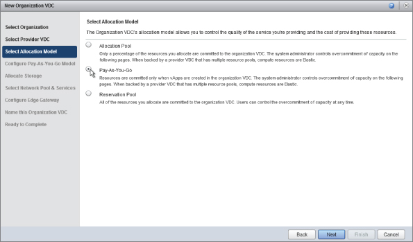
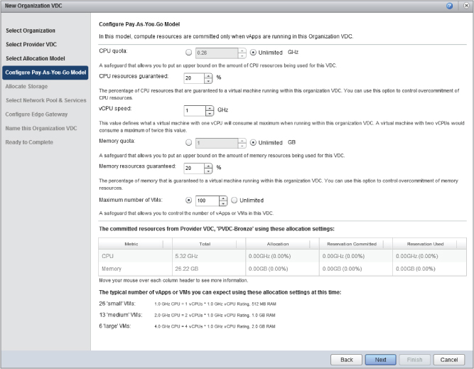
Next, you are shown the various options for configuring how resources are allocated in the Pay-As-You-Go allocation model, as illustrated in Figure 8.68.
Figure 8.68 Pay-As-You-Go allocation model options
Pay-As-You-Go operates on a per-VM basis. Rather than creating a pool of finite capacity as in the Allocation and Reservation Pool models, it creates a resource pool whose size is derived from a cumulative total of VM resources.
Resources are committed in the Org vDC only when the vApp is started. As such it is treated as an infinite pool of resources to your consumers, while still being constrained by the limits of the resources available in the underlying PvDC.
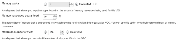
CPU Quota, Memory Quota, and Maximum Number Of VMs settings can be applied to control the maximum amount of resources that this Org vDC consumes before it runs out of resources, or they can be set to unlimited. If they are set to unlimited, consumers can create vApps until the resources are physically exhausted. Pay careful attention to the amount of resources consumed to ensure there is sufficient capacity provided to meet demand. However, each organization does have to be configured with an allocation of resources (which they may or may not use). Pay-As-You-Go is most commonly found in development or hybrid/auto-scaling environments, where there are highly variable numbers of VMs on a day-to-day basis.
The Pay-As-You-Go model allows you to define a standard unit of computing in terms of a maximum CPU speed, expressed in GHz per vCPU with a level of resources guarantee. For example, Figure 8.69 shows a standard maximum unit of allocation of 1 GHz per vCPU with 20 percent guaranteed (0.2 GHz). This setting allows for fairly high levels of overcommitment of CPU resources. Likewise, similar settings can be applied for memory (Figure 8.70).
Figure 8.69 CPU settings in Pay-As-You-Go model
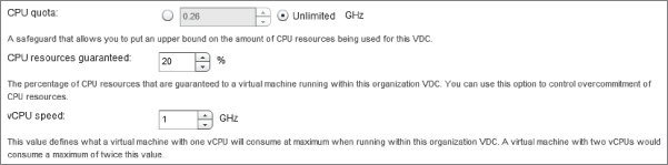
Figure 8.70 Memory settings in Pay-As-You-Go model
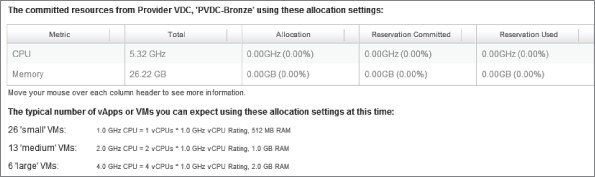
The wizard computes the typical number of VMs that could be deployed if you use this allocation model (Figure 8.71).
Figure 8.71 Committed resources in Pay-As-You-Go model
You'll notice in Figure 8.68 that unlike the Allocation and Reservation Pool models there is no allocation for the Pay-As-You-Go Org vDC. This is because resources from the PvDC are committed only when vApps are started and continue until resources are exhausted, at which point consumers will be prevented from starting further vApps.
Configuring the Org vDC for the Reservation Pool Model
In this example you will be using the Reservation Pool allocation model for the ORG-vDC-Sales-Production Org vDC. This example Org vDC is designed to support workloads that require 100 percent guaranteed resources and the ability for individual consumers to control resource allocations for individual VMs. The Org vDC is constructed from the elements highlighted in Figure 8.72.
Follow the same process as in the previous examples to add another Org vDC. However, when prompted for the allocation model choose the Reservation Pool model, as shown in Figure 8.73.
Figure 8.72 Resources that comprise the ORG-vDC-Sales-Production Org vDC
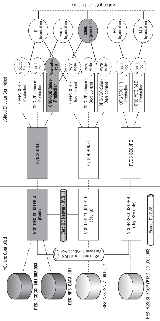
Figure 8.73 Selecting the Reservation Pool allocation model
In this model, the Org vDC is allocated a fixed number of resources from the underlying PvDC. In the example shown in Figure 8.74, you'll allocate 8 GHz of CPU and 16 GB of RAM from the Gold PvDC.
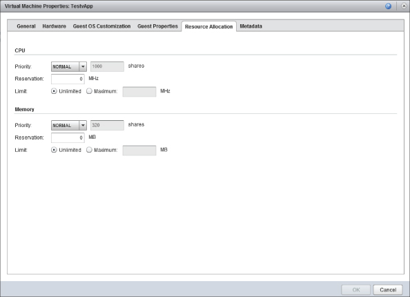
This model is similar to the Allocation Pool model, except it enables the consumer to control commitment on a per-VM basis. If you look at the properties of a VM that resides in an Org vDC using the Reservation Pool model, as shown in Figure 8.75, you can see that the consumer can set the appropriate resource reservations for their own VMs. This option is not available for VMs running in Org vDCs using the Allocation Pool or Pay-As-You-Go allocation models.
There is no need for you to define a reservation level for the resources allocated to the Org vDC—all resources are 100 percent reserved in this model.
Figure 8.74 Reservation Pool settings
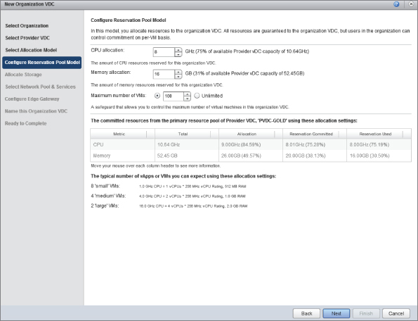
Figure 8.75 Setting individual VM resource allocations when using the Reservation Pool model
The Reservation Pool model is one of the more expensive allocation models in vCloud Director because it dedicates physical resources to an Org vDC when it is created. This means those resources are not available to other organizations using the same underlying PvDC even if they are not being used.
The Reservation Pool model always guarantees resource availability to its consumers but allows the resource allocation of individual VMs to be delegated to consumers rather than being set at an Org vDC level.
Allocating Storage
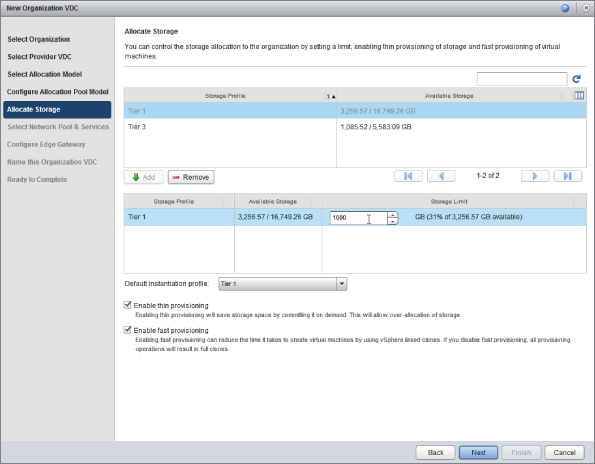
Once you have configured your allocation model, you have a choice of how much storage you wish to allocate to your Org vDC and how it will be provisioned. This builds on the work you did earlier to define storage tiers using storage profiles and maps them to PvDCs.
In this example our Org vDC will be consuming Tier 1 storage that is presented to the PvDC-Gold PvDC. It is also possible to consume Tier 3 storage, but given that this Org vDC is intended for service production workloads, we will enable it to work only with Tier 1 storage.
As shown in Figure 8.76, a limit of 1 TB (1,000 GB) is set for this Org vDC. Thin-provisioning and fast-provisioning are also enabled.
Figure 8.76 Allocating storage to an Org vDC and setting a quota of 1000 GB
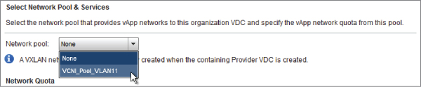
Allocating Networks
The next step in the wizard allocates networks to your Org vDC. You are prompted to choose a network pool from which organization and vApp networks will be created. In this example you are using VCNI rather than VXLAN because the physical network does not yet support the system requirements of VXLAN. You must select the appropriate network pool from the drop-down box, as shown in Figure 8.77.
Figure 8.77 Selecting the network pool
You can specify a quota, as shown in Figure 8.78, which determines how many networks this organization is allowed to deploy from the pool. This will dictate the maximum number of Organization and vApp networks that can be configured in this Org vDC.
Figure 8.78 Specifying a network quota
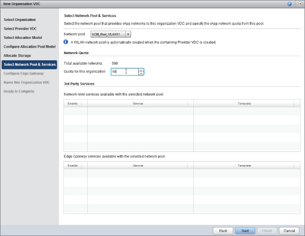
In this example you'll allocate a quota of 50 networks from this network pool. That means this organization can deploy up to 50 networks, which are allocated from the cloud-wide network pool of a possible 500.
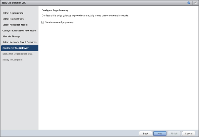
In the next step, you are prompted to create a vCNS Edge Gateway. In this example the IT department vApps will be directly connected to the corporate WAN. We will look at the vCNS Edge Gateway later in this chapter; for now, choose to skip creating it at this time, as shown in Figure 8.80.
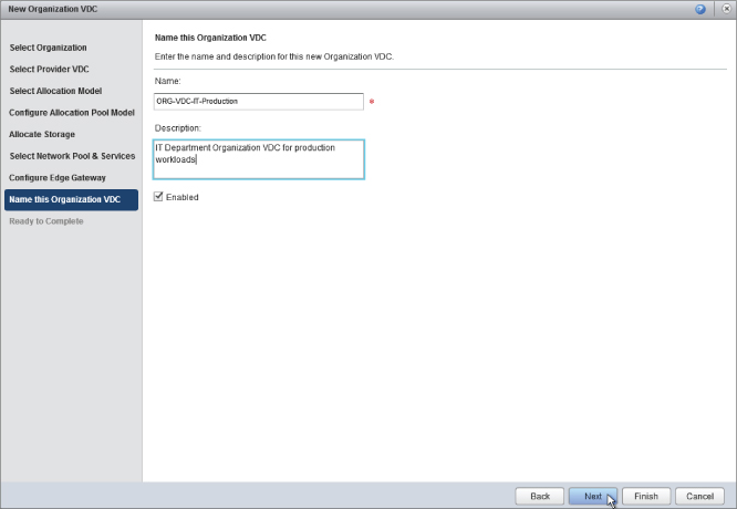
You are prompted to enter a name for the Org vDC you have just created. As shown in Figure 8.79, you are going to call it ORG-vDC-IT-Production, denoting that this is a virtual datacenter allocated to the IT organization that is capable of supporting production workloads.
Figure 8.79 Naming the new Org vDC
Using an easy-to-understand and consistent naming approach makes it easier for your consumers to determine the most appropriate place to deploy their workloads.
You can deselect the Enabled check box to configure the Org vDC without making it available to your consumers. This prevents your consumers from deploying workloads before the environment is fully configured.
Figure 8.80 Skip creating a vCNS Edge Gateway at this stage.
Once you've checked all the details you have entered, click Finish to create the Org vDC in vCloud Director.
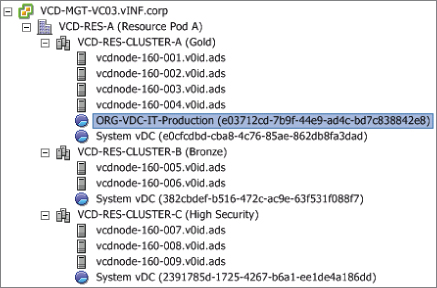
If you use the vSphere client to inspect the clusters that underpin the PvDC-Gold PvDC, you'll see that a resource pool object has been provisioned to represent the Org vDC you've created, as shown in Figure 8.81.
Figure 8.81 created Org vDC as shown from vSphere Client
You have now created an organization that is a logical authentication and administrative boundary. You have also allocated and created an Org vDC that represents an allocation of physical computing, storage, and network resources from a PvDC.
Connecting an Org vDC to the External Network
Now that you have created an Org vDC for the IT department, you need to provide a method of connecting to the corporate datacenter network. You can do so in one of two ways:
- Connect with an vCNS Edge Gateway
- Connect directly to an external network
As shown in Figure 8.82, you will be connecting the IT department directly to the external network. This is known as a direct Org vDC network. Later examples will show how the vCNS Edge Gateway can be used.
As the system administrator, you need to connect the Org vDC directly to the corporate datacenter network. This will allow the IT department to set up various shared services within the vCloud environment such as Active Directory and antimalware services.
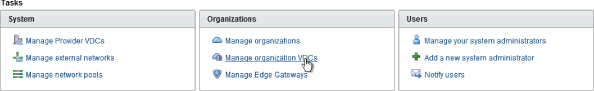
From the Tasks section on the Home screen, click Manage Organization VDCs to browse the list of Org vDCs, as shown in Figure 8.83.
Figure 8.82 Direct Org vDC network
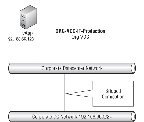
Figure 8.83 Choosing Manage Organization VDCs
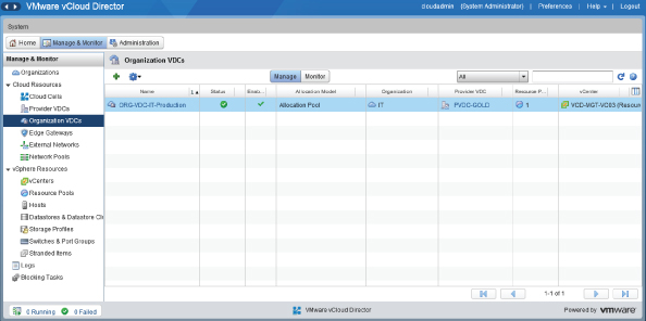
Double-click on the ORG-vDC-IT-Production Org vDC you created in the previous step (Figure 8.84).
Figure 8.84 Administering Org vDCs
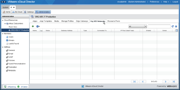
Select the Org vDC Networks tab. You'll note in Figure 8.84 that none have been defined yet. Click the green + symbol shown in Figure 8.85 to add a network. You are going to create an organization network that is directly connected to the CorpDatacenterNetwork.
Figure 8.85 Creating an external network
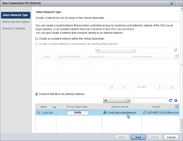
In this example we are going to create an external network that is directly connected (bridged) to the datacenter network. To do so, select Connect Directly To An External Network, as shown in Figure 8.86.
Figure 8.86 Creating a directly connected Org vDC network
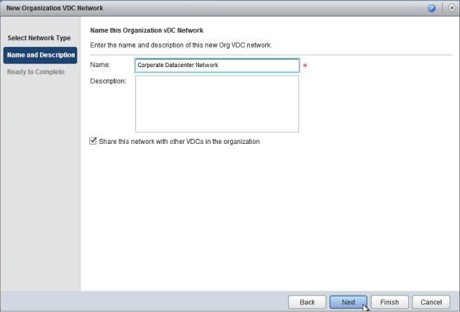
Enter a name for this organization network, as shown in Figure 8.87, and choose to share it with other Org vDCs that are created in the IT organization.
Figure 8.87 Naming the Org vDC network
When you click Next, you are shown a summary screen (Figure 8.88) confirming that we are creating a direct Org vDC network connected to the CorpDatacenterNetwork external network. Click Finish to create the network. You'll then be able to review that the ORG-vDC-IT-Production Org vDC has a new Org vDC network added to it.
Figure 8.88 Direct Org vDC network created within the IT department Org vDC
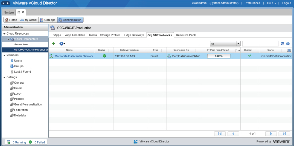
Our IT department now has a way of connecting vApps directly to the external corporate datacenter network so that vCloud-hosted vApps can participate directly on the corporate WAN.
Creating a vCNS Edge Gateway
The previous example connected the Org vDC directly to the corporate datacenter network. This is fine for use cases where you want your vApps to be directly on the corporate network(s); however, one of the most powerful features of vCloud Director is its ability to create isolated vCloud networks. These can be used to provide isolated network segments, or network segments that have limited access to the corporate WAN, either to isolate particular traffic or as part of a strategy to reduce the number of IP addresses consumed on the corporate WAN.
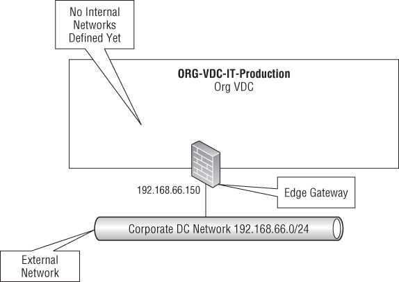
Next you'll use a wizard that will allow our ORG-vDC-IT-Production Org vDC to connect to the external network via an vCNS Edge Gateway, as illustrated in Figure 8.89. At this stage the edge network is all you'll be configuring, but in Chapter 9, “Consuming Services,” you'll create internal networks that use our vCNS Edge Gateway to connect to the corporate DC network.
Figure 8.89 vCNS Edge Gateway attached to our Org vDC
To enable the connectivity shown in Figure 8.89, you need to create an vCNS Edge Gateway. You do this for each Org vDC or external network that you are connecting to. You can create more than one vCNS Edge Gateway for an Org vDC if required.
As the system administrator, navigate to the Manage & Monitor tab, as shown in Figure 8.90, and open an Org vDC. In this example we will be adding a vCNS Edge Gateway to ORG-vDC-IT-Production.
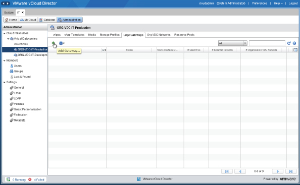
Navigate to the vCNS Edge Gateways tab and click the green plus symbol to add a new vCNS Edge Gateway, as shown in Figure 8.91.
Figure 8.90 Opening the Org vDC
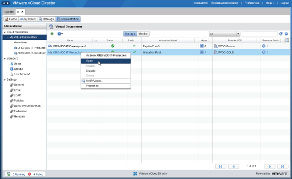
Figure 8.91 Adding a vCNS Edge Gateway to an Org vDC
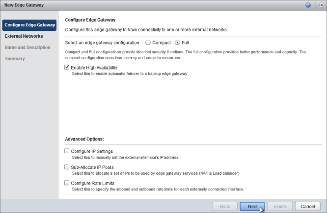
You'll be presented with a wizard, as shown in Figure 8.92. In this example you are building an vCNS Edge Gateway for a production Org vDC, so choose the Compact and Enable High Availability options. You will have the vCNS Edge Gateway's IP address assigned from the network pool, so leave Configure IP Settings unchecked. The remaining two options are not required to deploy the vCNS Edge Gateway and can be configured later if required.
Figure 8.92 vCNS Edge Gateway configuration settings
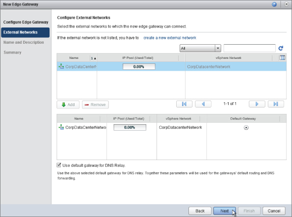
The wizard prompts for details of the external networks that this vCNS Edge Gateway will connect to. You will be connecting it to the CorpDatacenterNetwork, as shown in Figure 8.93, and using it to provide private network options within the Org vDC. One of the major new features of the vCNS Edge Gateway in vCloud Director 5.1 is its ability to support more than one network, which is a significant improvement over previous versions (which supported only two networks).
Figure 8.93 Configuring an external network
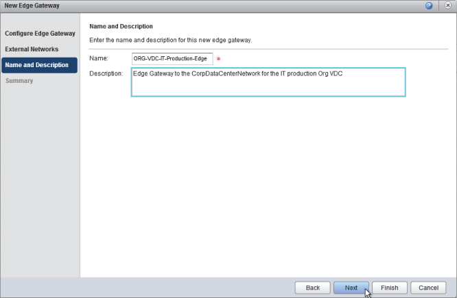
In this example, you'll be using the vCNS Edge Gateway to relay DNS requests to the corporate DNS servers that were configured as part of creating the external network earlier in this chapter. Enter a name and description for the vCNS Edge Gateway, as shown in Figure 8.94. Again, keeping a consistent naming scheme helps administrators and consumers understand what elements are connected to what.
Figure 8.94 Naming a new vCNS Edge Gateway
When you click Finish to complete the configuration, vCloud Director communicates with the vCNS Manager to deploy a vCNS Edge Gateway appliance and configure it with connections to the appropriate networks. You can see the IP address that it has been allocated by browsing the properties of the vCNS Edge Gateway and looking at the Configure IP settings tab.
The default configuration has the vCNS Edge Gateway firewall configured to drop all traffic. If you want to test connectivity by pinging it, you'll need to create a firewall rule via the Firewall tab to enable this traffic, as shown in Figure 8.95.
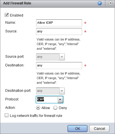
Browse to the Firewall tab and click Add to create a new firewall rule to allow ICMP traffic (Figure 8.96).
Figure 8.95 Choosing vCNS Edge Gateway Services
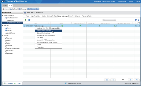
Figure 8.96 Adding a rule to allow ICMP ping traffic to the vCNS Edge Gateway
Creating an Initial Service Catalog
By this point, as the cloud administrator, you have completed the base build tasks of the vCloud platform. You've allocated resources, connected them to external networks, and created one or more organizations to represent your consumers.
At this stage your initial consumers are likely to be the organization administrators of the various organizations you've implemented in your vCloud platform. Because of the way control is delegated to these organization administrators, they can then configure who is able to access each organization and create whatever catalogs, templates, and configurations they require.
Now it's time to let them use the service. One of the key attributes of cloud computing is self-service, so in that spirit you can provide the URL to each organization and they should be able to log on using the directory source (which you defined earlier) to authenticate. From there, your consumers can create vApps, catalogs, and so on, and can deploy services.
Creating a Public Catalog
Our IT organization will be maintaining a number of standard operating system images and installation media for use and customization by consumers within other organizations such as sales and finance. In this section you'll import installation media in the form of ISO files. You'll also import existing VMs from vCenter Server in OVF format. To do so, you'll create a catalog owned by IT but published to other organizations in your vCloud Director deployment.
If other organizations wish to use items published in a public catalog, the organization administrators of each respective organization can copy the items to a local catalog and allow consumers to deploy from there. Consumers are unable to deploy directly from a public catalog.
You should note that media files are also associated with a particular Org vDC. Although you can copy media from a public catalog to a local catalog in order to mount those media files from VMs in an Org vDC, you need to copy them to each Org vDC.
To achieve this, you'll log on to the vCloud Director portal as the IT organization (itadmin), rather than the system administrator account (cloudadmin), as shown in Figure 8.97. To do so, you must use an organization-specific URL that was generated when the organization was created—in this case, https://vcloud.vinf.corp/cloud/org/IT/.
Figure 8.97 on to vCloud Director as itadmin
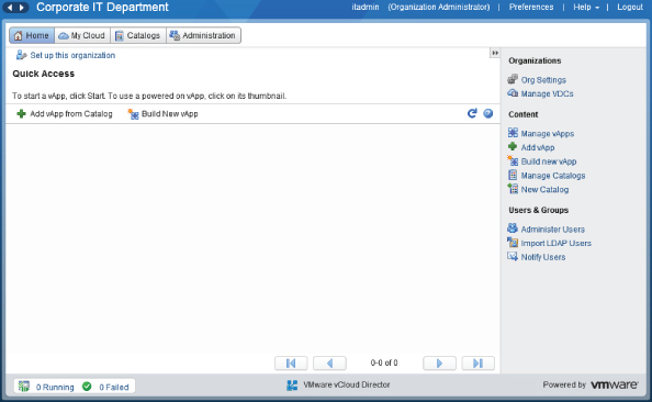
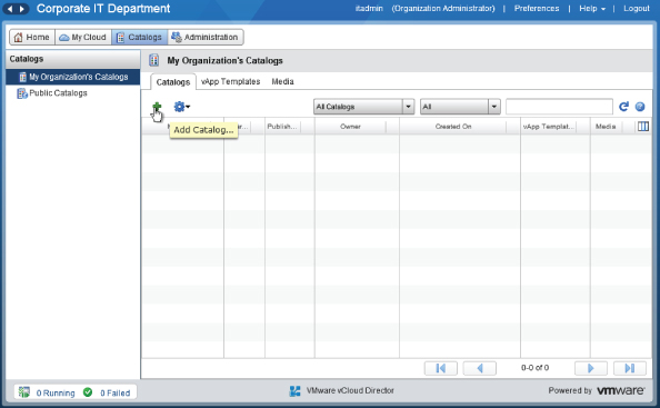
Your first task for the IT organization will be to create a catalog that you can publish as a public catalog that other organizations in our company can download from. Select the Catalogs tab and then click the green plus button to add a catlog, as shown in Figure 8.98.
Figure 8.98 Creating a catalog in the IT organization
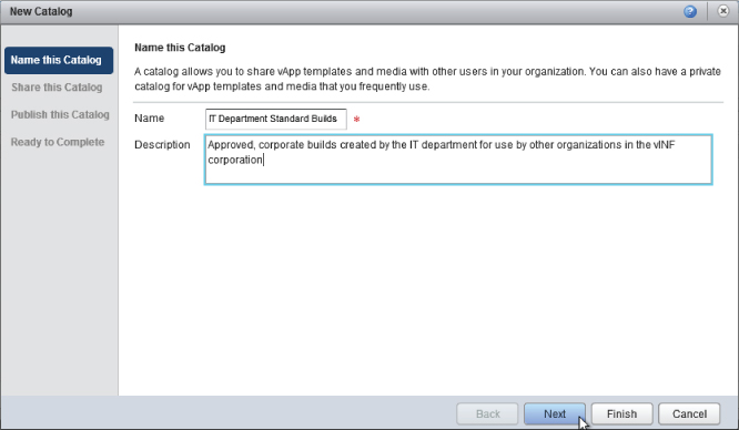
As shown in Figure 8.99, a wizard launches that lets you create a new catalog. Name the catalog IT Department Standard Builds and provide a description for consumers when they are browsing this catalog.
Figure 8.99 Naming a catalog
Next you must select who you want to share this catalog with. You want to create a public catalog that will be accessible to all organizations, but you want only members of the IT department to be able to create and delete catalog entries. Therefore, click Add Members and choose to share with everyone in the organization (in this case, the IT organization) with Read/Write access, as shown in Figure 8.102.
Next you are given the option to publish the catalog with other organizations. Your intention is to create a public catalog, so choose Publish To All Organizations, as shown in Figure 8.100.This is a binary setting so you can only make the catalog available to all organizations or none.
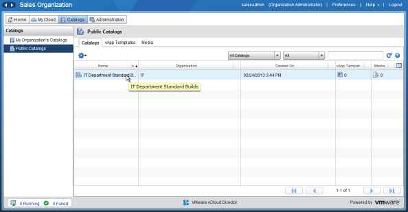
You should now see the IT Department Standard Builds catalog in your list of catalogs (see Figure 8.102). Other organizations will be able to see it as a public catalog (see Figure 8.103).
Figure 8.100 Publishing a catalog to all organizations in vCloud Director
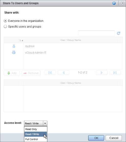
Figure 8.101 Catalog view within the IT organization
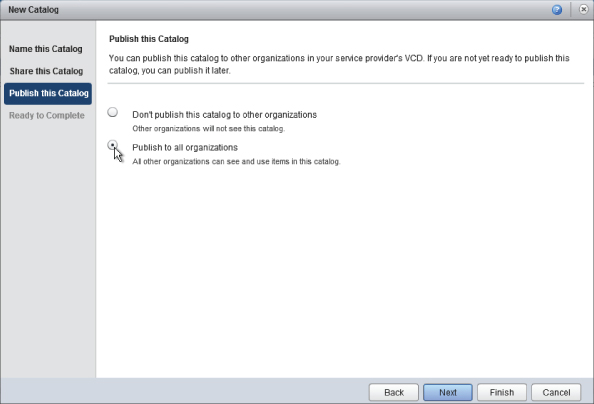
Figure 8.102 Granting all members of the IT organization full control of the new catalog
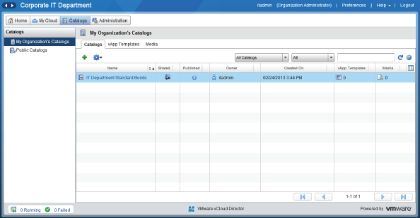
Figure 8.103 Public catalog created by the IT organization as viewed from the sales organization
Your IT department has now defined a public catalog that is visible from other organizations within your vCloud Director platform. The next step is to populate that catalog with media and VMs.
Uploading Media to vCloud Director
First, you'll import operating system installation media in ISO format. This allows the IT team to easily mount an installation disc image to an existing VM within the vCloud Director interface.
As the system administrator, you can also build VMs in vCenter and then import them into vCloud Director, but organization administrators cannot.
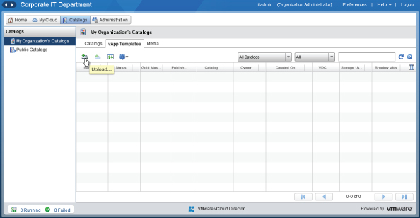
Select the Media tab to view the media section of the catalog. Then click the Upload icon, as shown in Figure 8.104.
The file upload feature uses a Java applet. If you get the error shown in Figure 8.105, you do not have an appropriate Java Runtime Environment (JRE) on your administrative workstation, and you'll need to download and install one before you can proceed.
Figure 8.104 Click the Upload icon
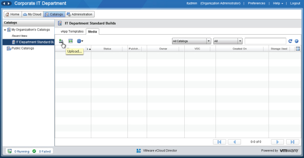
Figure 8.105 Missing Java Runtime Environment warning
If you click on the blue text, you'll be redirected to download an appropriate Java Runtime Environment (JRE) from the Oracle website, which you should install to continue.
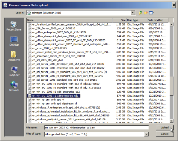
Next, in the Upload Media window, you'll select the ISO file you want to upload by clicking the Browse button, as shown in Figure 8.106. You'll be uploading a Windows 2003 R2 ISO file from a network share into vCloud via our administrative workstation by navigating to the file, as shown in Figure 8.107.
Figure 8.106 Upload Media
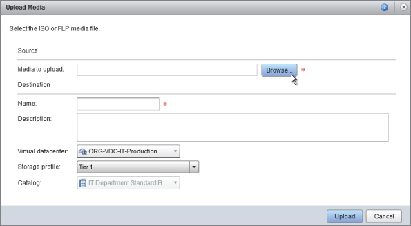
Figure 8.107 Selecting an ISO file to upload
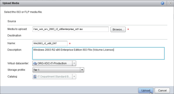
Enter some relevant information (Figure 8.108) about the ISO file you are uploading. It's a good idea to include some information about the CPU architecture and edition that the ISO file contains. The original filename won't be visible once it has been imported into vCloud Director, and using a structured naming convention makes it easier to search for.
Figure 8.108 Entering descriptive text for a media file
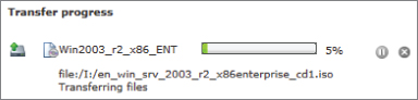
Click Upload to start the process. You'll see a window shown in Figure 8.109.
Figure 8.109 Upload progress
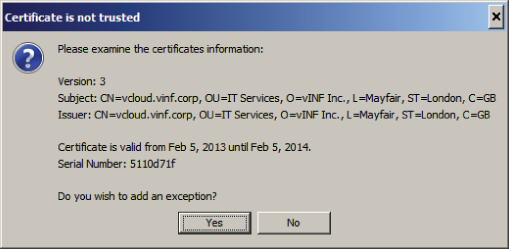
If you are using self-signed certificates for your cell servers, you may also see the confirmation window shown in Figure 8.110. Click Yes to add the exception for this session.
Figure 8.110 Self-signed certificate warning
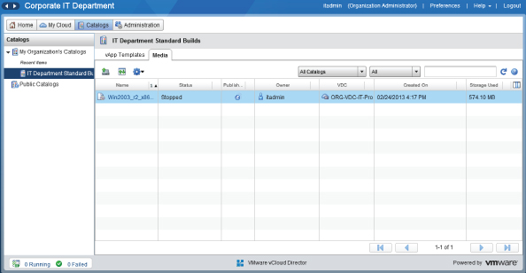
Depending on the size of your ISO file and the speed of the connection between your workstation and the cell server, this upload may take a while. When it has completed, in the vCloud Director interface the Status column will read Stopped, as shown in Figure 8.111.
Figure 8.111 Media file uploaded and ready to use
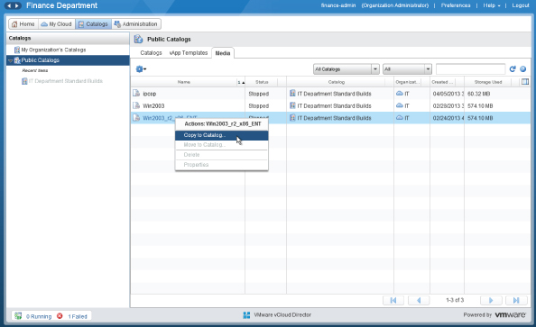
The ISO file you uploaded is now ready for use by other organizations. They can browse the public catalog you've just created and copy the media file to their own catalog files by right-clicking and choosing Copy To Catalog, as shown in Figure 8.112.
Figure 8.112 The media file is visible from the public catalog in the sales organization
Exporting a VM from vCenter for Use with vCloud Director in OVF Format
vCloud Director allows consumers to import their own VMs from other VMware platforms that support the Open Virtualization Format (OVF) standard. You can also download prebuilt and ready-to-use VMs as OVF files from many sources on the Internet. VMware maintains a marketplace for such virtual appliances from third-party vendors and community projects in the Marketplace section of their website:
https://solutionexchange.vmware.com
Alternatively, consumers can export an existing vCenter managed VM or template in OVF format and use it in vCloud Director.
vCloud Connector 2.0 can also be used to perform this export/import activity in a more streamlined manner if you have a large number of VMs to import.
This section assumes you have a VM ready to use in an existing (non-vCloud) vCenter installation. For example, you may have a standard vSphere template that you want to import for use with vCloud Director.
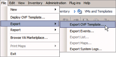
You can export the vSphere VM template to OVF format to a network share or portable drive using the VMware OVF Tool command-line utility or vSphere Client, as shown in Figure 8.113. You then reimport the template into vCloud Director from the catalog interface using a process similar to uploading media files.
Figure 8.113 Exporting a VM as an OVF file from vSphere Client
You can then upload the OVF template into vCloud Director via the web interface by clicking the Upload icon in the vApp section of the catalog, as shown in Figure 8.114.
Figure 8.114 Click the vApp OVF Upload icon.
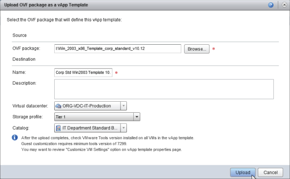
As you did in the previous task, enter some descriptive information, as shown in Figure 8.115. Then browse to the location of the OVF file that you wish to import and upload it into the vCloud Director catalog using the Java upload applet.
Once the upload has completed, you'll see that the upload is being finalized within the catalog. When that process finishes, the template will be available to other organizations with access to the public catalog.
Figure 8.115 Enter descriptive text for the template that you are importing and assign it to an Org vDC and storage profile.
Handing Over Access to Your Consumers
Once you have uploaded any required images for your vCloud public catalog, you have completed the main platform build tasks. You have defined a number of PvDCs, organizations, and Org vDCs in vCloud Director, and you are ready to hand over access to vCloud to your consumers so that they can start to build, upload, and configure their workloads. You've defined a framework in vCloud to marshal and control access to computing resources and provide a self-service interface that your consumers can interact with. The vCloud Director interface is self-explanatory, and its typical audience is system administrators rather than business end users.
In most organizations, you'll need to provide some basic training to your consumers—even to the more experienced system administrators, so that they can understand the logical abstractions you've created in vCloud Director. Ensuring you have logical naming conventions and completed description fields will pay dividends in consumer experience.
Summary
Once the vCloud Director management platform has been built, you follow a process of defining a group of physical computing, network, and storage resources into a PvDC. You can define several organizations within vCloud Director. An organization acts as an authentication and administrative boundary and, in a private cloud scenario, typically maps to a department, business unit, or subsidiary company. In a public cloud scenario, an organization typically represents a customer.
Each organization contains a number of consumers. These consumers can be identified and authenticated using a local user or linked to an external directory service, such as Active Directory or other LDAP authentication source. Each organization is configured for a specific authentication source, but it is possible to modify it after creation to use a different method—for example, moving from built-in user accounts to an external LDAP directory.
Using an external directory source requires an appropriate network communication path between your cell server(s) and the target directory. Ensuring this may involve firewall or VPN configuration if these services are in a highly secure or remote location.
Network resources are added to each PvDC and defined as external or internal networks. Internal network resources are allocated from a preconfigured network pool—a pool of VLANs that can be allocated, provisioned, and deprovisioned on behalf of consumerns by vCloud Director—to quickly deliver complicated network topologies to support vApps.
A number of networks are built as default object types within vCloud Director. As you build organizations and allocate resources to them, you'll define a number of logical organization internal and external networks, which in turn are connected to vSphere port groups and physical uplinks from PvDCs to the corporate datacenter.
As the system administrator, you can create one or more Org vDCs that represent allocations of resources from PvDCs. You must configure an allocation model for each Org vDC, choosing from three types: Allocation Pool, Pay-As-You-Go, and Reservation Pool.
Catalogs can be created to hold vApps (groups of VMs) and disc image media like ISO and FLP files. Organizations can be configured to allow them to publish catalogs of vApps and media with all other organizations in vCloud Director. A published catalog is known as a public catalog. If other organizations want to use components from the public catalog, they must copy them to their own catalog, from which they can be deployed. Apps are built from groups of VMs, which can be imported directly from a vCenter server or uploaded directly in OVF format by consumers. Consumers can build new vApps or choose VMs from the catalog to build their own vApps.
In the next chapter you'll build on our example design and look at how consumers from the HR, sales, and finance organizations can use the capacity you've provided to build, customize, and deploy vApps.