Chapter 7
Configuring and Managing Storage
IN THIS CHAPTER, YOU WILL LEARN TO:
- BECOME FAMILIAR WITH STORAGE CONCEPTS
- Learn the Basics of Storage in vSphere
- Learn the Types of Supported Storage
- Learn the Benefits of Remote Storage
- Guidelines for Implementing Storage
- CONFIGURE FIBRE CHANNEL SAN STORAGE
- Connect Fibre Channel Storage to an ESXi Host
- Manage Fibre Channel Storage on an ESXi Host
- Configure NPIV for Virtual Machines
- CONFIGURE ISCSI SAN STORAGE
- Become Familiar with ESXi iSCSI SAN Requirements
- Configure Hardware iSCSI Initiators if Present
- Configure Software iSCSI Initiators
- CONFIGURE NFS STORAGE
- Configure NFS Storage with ESXI
VMware ESXi natively provides virtualization of CPU, memory, network, and disk resources. The first three resources have to be utilized locally on the ESXi host. Disk resources can be utilized locally or remotely.
The addition of remote storage is one of the points where VMware ESX/ESXi leaves off and vSphere takes over. Without the ability to leverage remote storage shared across two or more hosts, vSphere would be no more than a few tools to manage one or more hosts.
By using remotely shared storage attached to multiple hosts managed by vCenter Server, vSphere can leverage the combined complement of CPU, memory, network, and disk resources across a cluster.
To get started, you must become familiar with how storage works with vSphere, how to leverage it, and the steps required to use it.
Become Familiar with Storage Concepts
To best leverage the types of storage available, you must have a firm understanding of the various types of storage, and when and why they should be leveraged. For administrators designing a new vSphere implementation, this information can be crucial to choosing the appropriate storage system that meets the needs of the implementation, while also adhering to the financial constraints of the project.
Learn the Basics of Storage in vSphere
For vSphere to be able to run virtual machines, the machines must reside on storage that the host can use. The storage can reside on local disks inside the host through locally attached storage, or can be remotely presented storage. Before we go into detail about local and remote storage, it is important that you understand how the storage is used for virtual machines.
Storage for guests, templates, and ISOs is referred to as datastores. Datastores are logical containers that obscure the storage subsystem from the virtual machines. Block datastores are formatted with the Virtual Machine File System (VMFS) format, which is an optimized, high-performance file system. Through the use of distributed locking for the virtual disk files, multiple virtual machines can be used on a single file system by one or more VMware ESXi hosts simultaneously. This ensures that Storage Area Network (SAN) storage is safe and reliable for storing virtual machine configuration, disk, and swap files. Network Attached Storage (NAS) relies on NFS’s native file system locking mechanisms, to ensure storage is safe and reliable.
Because VMFS is designed to be a clustered file system, VMFS lets multiple hosts access one or more datastores concurrently. On-disk locking is the process by which two or more hosts can access a shared file system without interfering with each other. This process is used to prevent more than one host from attempting to power on or operate the same virtual machine.
VMFS and NFS datastores contain virtual machine configuration files, virtual machine disk files, virtual machine swap files, directories, symbolic links, raw device mappings, and the like. VMFS on block storage maps these objects as metadata. The metadata is updated whenever files on the datastore are accessed or modified. This includes when guests are powered on or off, when guests are modified, and when any file attributes are modified. This metadata keeps all hosts with access to the datastore informed of the current status of any object on the datastore.
VMFS and NFS datastores can be configured through vSphere Client or through command-line options on storage systems that are recognized by the VMware ESXi host.
Table 7.1 outlines the supported maximum sizes by VMFS versions.
Table 7.1: Maximum sizes supported by VMFS versions
| Version | Maximum Size |
| VMFS5 | 64 terabytes (TB) per volume |
| VMFS3 | 2 terabytes (TB) per volume |
If a larger VMFS3 datastore is needed, datastores can be aggregated or extended through the use of extents, with a maximum combined size of 64 TB. Additionally, if the storage system supports the ability to grow the storage amount, datastores can be increased without having to power off any running guests on the datastore.
VMFS5 Improvements Over VMFS3
The following improvements are found in VMFS5:
- Greater than 2 TB LUN support
- Physical mode RDM supports disks larger than 2 TB
- Increased resource limits such as file descriptors
- Scalability improvements using VAAI
- Standardized on 1 block size (1 MB)
- On-line, in-place upgrades
- Can mount and unmount workflow in the vSphere Client
ESXi 5.0 supports two partition formats:
- The master boot record (MBR), which supports a maximum size of 2 TB.
- The GUID partition table (GPT), which has a maximum size of 64 TB.
With ESXi 5.0, if you create a new VMFS5 datastore, it will be formatted using GPT by default. VMFS3 continues to use the MBR format. If you are using existing VMFS3 datastores and additional space is required, consider upgrading the datastore to VMFS5.
When you are designing how storage is to be provided to vSphere hosts, keep in mind that it is difficult to determine peak-access times or optimize performance by looking at individual virtual machines. It is a best practice to run a mix of high- and low-utilization virtual machines across multiple hosts to provide an even balance of CPU and storage operations. In addition to evenly distributing the workload across datastores, remember the following guidelines:
- Only configure one VMFS datastore for each LUN presented to ESXi hosts.
- Choose a Redundant Array of Independent Disks (RAID) level that is appropriate for the type of workload the virtual machines will be running on the disk stored on the datastore. Disk RAID levels should be configured as if the virtual disks were running on a physical system.
You need to consider whether to use a few large LUNs or many small LUNs. The key features of each method are described in the following list:
- When using a few large LUNs:
- It’s easy to create guests without having to continually provision space.
- More space is available for snapshots and disk resizing.
- You won’t have as many datastores to manage.
- When using many smaller LUNs:
- Space is optimized and storage is allocated on an as-needed basis, resulting in less wasted space.
- Many RAID levels are required for different virtualized workloads.
- You can leverage disk shares and multipathing for greater flexibility.
- Performance tends to be better.
- Microsoft Cluster Service requires each cluster disk resource to be in its own LUN.
Learn the Types of Supported Storage
VMware ESXi supports two basic types of storage:
Local storage is storage that is physically present in the host. This storage can either be physically housed in the host system or attached to the host using a storage controller connected to an external enclosure.
Remote storage is storage that is not physically attached to the host. It can include storage accessible to the host via a SAN or via a NAS device.
vSphere supports four disk types, as shown in Table 7.2. Keep in mind that the storage controller must be on the Hardware Compatibility List (HCL). Always refer to the current HCL reference documents at http://www.vmware.com/go/hcl.
Table 7.2: ESXi recognized disk types
| Type | Installation and Booting | Virtual Machine Storage |
| SCSI | Yes | Yes |
| SATA | Yes | Yes |
| IDE | Yes | No |
| ATA | Yes | No |
When you are working with local storage, the most important detail to remember is that the listed disk types are only supported if VMware ESXi supports the appropriate driver for the physical controller. For example, an Intel ICH7 SATA controller was initially supported in ESX 3.5 but is no longer supported.
To leverage the abilities of VMware High Availability, vMotion, Storage vMotion, Distributed Resource Scheduling, Distributed Power Management (DPM), and Fault Tolerance, VMware ESXi must utilize storage that is shared among several VMware ESXi hosts. For two or more hosts to share storage, that storage cannot be local to the ESXi host, but rather must be remote.
The following types of shared storage solutions are supported:
- Fibre Channel SAN
- iSCSI
- NFS
Remotely accessed storage is certified by VMware based on criteria such as the storage controller, the protocol being used to access that storage, and the backend disks in the storage system. This means that not every kind of Fibre Channel SAN, iSCSI, and NFS storage solution is supported. All three types of remote storage still have to be certified for proper support from VMware in the event of an issue. However, some storage solutions that are not on the HCL do work properly. When using the NFS protocol, storage may be supported, as long as the device providing the NFS storage is using the NFS v3 protocol.
Learn the Benefits of Remote Storage
Using ESXi with remote storage can make storage more flexible, more efficient, and more reliable if implemented properly. Additional remote storage features can include failover and load-balancing technologies. Often, a single storage system is used, providing a central location for storage management.
Implementing vSphere with remote storage offers the following benefits:
- Data is often redundant with approved remote storage systems.
- Multiple paths can be configured to access the remote storage, removing a single point of failure for storage systems.
- ESXi hosts support multiple paths to storage systems automatically and provide available paths to any guests residing on the remote storage.
- Multiple paths and redundant storage systems make guest availability less prone to host failures.
- In the event of a host failure, guests are immediately available to be recovered on other hosts in the environment that have access to the same remote storage.
- Guests can be migrated from one host to another while still running via VMware vMotion.
- Remote storage provides for the immediate recovery of guests after a host failure when used in conjunction with VMware HA (High Availability).
- Remote storage allows for the use of VMware Distributed Resource Scheduler (DRS) to load-balance guests across all hosts in a cluster.
- Remote storage allows guests uninterrupted operation when performing host maintenance—such as patching, upgrades, or host replacement—when used in conjunction with VMware vMotion and DRS.
- Leveraging remote storage also allows the use of Distributed Power Management (DPM) by consolidating workloads down to fewer hosts and shutting down the vacated hosts, facilitating lower overall power consumption.
All of these benefits of remote storage result from hosts sharing access to the remote storage in a vSphere environment coupled with the mobility of the VMware guests that reside on this remote storage. When guests are stored on shared storage, they can easily be moved from one host to another through hot or cold migrations.
Hot vs. Cold Migrations
A hot migration is simply the process of migrating a guest from one host to another while the guest is still operating. This task can be accomplished by purchasing a vSphere license that includes the VMware vMotion technology. CPU compatibility requirements between hosts are also required.
A cold migration refers to the task of migrating suspended or powered-off guests from one host to another. When used with shared storage, cold migrations do not have any CPU compatibility requirements as long as the guest is powered off.
Following are some of the typical operations that can be performed when using shared storage:
Zero or Minimal Guest Downtime Zero downtime can be achieved by migrating guests from one host to another using vMotion or VMware DRS. Minimal downtime can be achieved by powering off or suspending guests, followed by migrating them to other hosts.
Guest Workload Balancing VMware DRS allows you to manually or automatically migrate guests from one host to another to maintain an even level of host resource utilization.
Consolidated Storage When hosts use centralized storage, all guests can be stored in the same location rather than on individual hosts. Compared to storing guests on individual hosts, consolidated storage allows for greater flexibility among hosts as well as a simplified storage architecture.
Disaster Recovery Centralized storage provides for a central location to perform guest backups and restores. When vSphere is coupled with a storage system that incorporates replication, guests can be replicated to an alternate location for greater flexibility in recovering guests. Guests can then be restarted on hosts in the alternate location.
Simplified Storage Upgrades and Migrations When new storage is purchased, Storage vMotion allows live migrations to be performed without interrupting end users.
Guidelines for Implementing Storage
The following guidelines apply to all three kinds of storage (Fibre Channel SAN, iSCSI SAN, and NFS):
- Choose the appropriate virtual SCSI controller for virtual machines. When creating a virtual machine, the wizard preselects the default controller based upon the operating system selected on the guest operating system page. The LSI Logic SAS and the VMware Paravirtual controllers are available only on virtual machine hardware version 7 guests or higher.
- Virtual machine volume management software cannot mirror most virtual disks. Windows dynamic disks are an exception but must be specially configured to operate properly.
The following guidelines apply to Fibre Channel SAN and iSCSI SAN storage:
- Make sure the hardware and firmware versions are compatible with vSphere ESXi hosts.
- ESXi does not support iSCSI- or Fibre Channel–connected tape devices.
- Configure only one VMFS volume for a presented LUN.
- Only configure a diagnostic partition if using a diskless (SAN boot) configuration.
- Raw device mappings should be used for raw disk access (to leverage SAN hardware snapshotting), for clustering a virtual machine with a physical machine as well as virtual-to-virtual clusters. VMware recommends all cluster data and quorum disks should be RDMs. They also can be useful for physical-to-virtual (P2V) backout plans.
- Guest-based multipathing software cannot be used to load-balance a single physical LUN.
- In Windows virtual machines on a SAN, increase the SCSI Timeout value to 60 for better tolerance of I/O delays caused by path failover or other quiesce or stun operations.
- Here are some LUN considerations:
- LUN IDs must match across all hosts.
- Provision LUNs to the appropriate host bus adapters (HBAs) and provision all iSCSI storage targets before attaching ESXi hosts to the SAN.
- Make LUNs available to all hosts for greater flexibility using High Availability, DRS, Fault Tolerance, and vMotion.
- Remember to keep LUN IDs consistent across hosts. HBA failover is only possible if appropriate HBAs see the same LUNs.
- Ensure all systems have consistent paths to all SAN storage processors to prevent path thrashing, which can occur when vMotion or DRS is used with an active/passive SAN. (Path thrashing occurs when multiple hosts attempt to use different paths to access a datastore and cause the datastore to become unavailable.)
Configure Fibre Channel SAN Storage
Fibre Channel storage was the first supported shared storage for VMware ESX and remains a viable shared storage solution with vSphere. There are many SAN storage vendors on the market.
TIP Before choosing any particular vendor and product offering, ensure it is on the HCL. The VMware HCL can be found here: www.vmware.com/go/hcl.
When implementing a SAN, keep the following in mind, as well as the items in “Guidelines for Implementing Storage,” earlier in this chapter:
- Traditional SAN-based tools will not be visible to the virtual machines file system; only the ESXi operating system will be visible. You will have to use vSphere Client to monitor virtual machines.
- Use disk shares and Storage I/O Control (SIOC) to prioritize virtual machines sharing the same LUN.
- Here are some Fibre Channel HBA considerations:
- When using multiple HBAs, use the same model and firmware revision for all of them.
- A single HBA may be used for storage traffic, with a secondary HBA for failover. LUN traffic can be manually balanced across the HBAs for greater throughput on certain active/active SAN arrays. Set Path Policy to Fixed when using this configuration.
- Set the timeout value for detecting a path failure in the HBA driver. For optimal performance, set this timeout to 30 seconds; and for Windows guests set the standard disk timeout value within the operating system via the registry to 60 seconds.
- Configure proper HBA BIOS settings as well as queue depth if the configuration calls for something other than the default.
Fibre Channel storage can also be used for the ESXi installation. To use a Fibre Channel LUN to house the ESXi boot image, keep the following in mind:
- The HBA BIOS must be properly configured to access the SAN and presented LUNs.
- Because drivers scan the PCI bus in an ascending fashion, placing HBAs in the lowest slot number will allow drivers to detect them quickly.
- Whether using a single HBA in a non-redundant configuration, or dual HBAs in a redundant configuration, only a single path is available to hosts.
- The boot LUN having a LUN ID of 0 should be accessible only to the associated ESXi host that will be using the LUN.
- When booting from an active/passive SAN, ensure the designated storage processor’s World Wide Name (WWN) is active. If the storage processor is passive, the ESXi host will fail to boot.
- Connections from the ESXi host must be made through a SAN fabric. Connecting HBAs directly to storage or through arbitrated loops is not supported.
Connect Fibre Channel Storage to an ESXi Host
In a typical configuration, Fibre Channel (FC) storage is used as a shared storage system for ESXi hosts. The vast majority of Fibre Channel storage implementations are configured in this manner. Because each Fibre Channel storage vendor has its own configuration parameters, a general installation guide cannot completely address all configuration steps for the available storage configurations available.
The basic process of connecting ESXi hosts to an FC SAN is as follows:
1. Connect FC cables from the ESXi host HBAs to the FC fabric.
2. Connect the FC cables from the storage array front-end ports to the FC fabric.
3. In the FC fabric configuration, zone the ESXi host HBAs to the front-end storage array ports using single initiator zoning.
4. Create LUNs and map them to ESXi hosts through the storage array’s native presentation methods.
5. Configure multipathing as needed on the ESXi host.
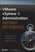
ESXi hosts can now see the available LUNs when the HBAs are rescanned, as shown in Figure 7.1.
Figure 7.1: Fibre Channel devices displayed in vSphere Client
To configure and connect a specific vendor’s storage system, consult VMware’s Fibre Channel SAN Configuration Guide and the documentation specific to the storage system and VMware ESXi.
Manage Fibre Channel Storage on an ESXi Host
To get started with configuring FC-based datastores, the ESXi host must be aware of the LUNs that have been mapped to it. ESXi hosts will automatically scan the HBAs on initial bootup to determine which LUNs are available. If SAN storage is attached to a host after it has booted, a simple HBA rescan is required.
The time it takes to rescan the HBAs depends on the number of LUNs that are being presented to the HBAs. This does not typically take long, but it can delay the boot time of an ESXi host. The fewer LUN IDs to scan, the more quickly a host can continue with the boot process.
Modify the LUN Scanning Parameters
The VMkernel scans for LUN IDs from 0 to 255, giving a total of 256 possible LUNs for the host to recognize. Modifying the Disk.MaxLUN setting will improve the LUN discovery speed. The number of LUNs is not the only determining factor in the discovery speed, but it is a good place to start.
To change the maximum number of LUN IDs to scan, follow these steps:
1. From vSphere Client, select a host from Inventory.
2. Select the Configuration tab in the software panel and click Advanced Settings.
3. Select Disk from the list of options on the left of the Advanced Settings menu.
4. Scroll down to the Disk.MaxLUN setting.
5. Enter the largest LUN ID setting you want to scan to. For example, if LUN IDs from 0 to 30 are mapped by the SAN, enter 30 and click OK.
Sparse LUN support, enabled by default for ESXi, provides the ability to see multiple LUNs that are not sequentially numbered. For example, if you have LUN IDs of 0, 1, 3, and 6 mapped on the FC fabric, without sparse LUN support, only LUN IDs 0 and 1 would be visible to hosts in the same zone.
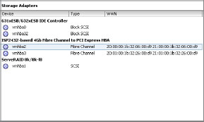
If LUN IDs are sequentially numbered, however, the discovery time can be shortened by disabling sparse LUN support. Figure 7.2 shows the setting to change to disable sparse LUN support.
Figure 7.2: Changing the sparse LUN support setting
WARNING Only disable sparse LUN support if LUNs are sequentially numbered.
Take the following steps to disable Sparse LUN support:
1. From vSphere Client, select a host from Inventory.
2. Select the Configuration tab in the software panel, and click Advanced Settings.
3. Select Disk from the list of options on the left of the Advanced Settings menu.
4. Scroll down to Disk.SupportSparseLUN, and set the value to 0.
5. Click OK.
Rescan Storage Adapters
Rescanning the storage adapters will scan the attached storage in an attempt to discover LUNs. After rescanning the storage adapters, any storage that is available to the host’s HBAs will be visible in the Details panel on the Configuration tab under Storage Adapters in the Hardware panel. To rescan storage adapters, follow these steps:
1. In vSphere Client, select a host from Inventory and click the Configuration tab.
2. In the Hardware panel, select Storage Adapters.
3. Because no datastores have been added, you only have to select Rescan All from the top-right corner of the screen.
4. To update a datastore after its configuration has been changed, select Refresh from the top-right corner of the screen.
5. If new LUNs are discovered, they will appear in the details panel. LUNs discovered after performing a rescan operation appear in the Details area of the Storage Adapters section of the vSphere Client (see Figure 7.1, earlier in this chapter).
Review and Configure Device Paths
Before attempting to create FC-based datastores, it is important to ensure that the storage paths are properly configured. SANs typically operate in an active/passive or active/active configuration.
These configurations require different path settings, depending on the configuration. It is best to follow the SAN manufacturer’s recommendations when choosing the proper path configuration.
The following process will give you a better view of what paths are currently being used to communicate with attached storage:
1. From vSphere Client, select a host from Inventory.
2. Select the Configuration tab. Click Storage in the Hardware panel.
3. In the View panel, select Devices, then select the device you want to review.
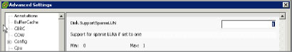
4. Click Manage Paths on the right side of the Device Details panel.
5. Notice the Path Selection Policy in the top section of the Manage Paths dialog box. Figure 7.3 shows one of the three default VMware-provided path policies.
6. Depending on the type of SAN system the HBA is connected to, choose an appropriate path policy. The three default types are as follows:
Fixed Uses a preferred path. If the path is unavailable, an alternate is chosen until the preferred path is available again. Active/active SANs typically use the fixed policy.
Most Recently Used (MRU) Uses any available path. If the current path becomes unavailable, an alternative is chosen. When the original path is available again, the path is not moved back and stays on the most recently used path. Active/passive SANs typically use the MRU policy.
Round Robin Uses an automatic pathing algorithm to determine the best path. Round robin is designed to better load-balance storage paths and I/O performance.
Additionally, any third-party path policies will be displayed if they are installed on the host. Currently, only EMC and Dell Equallogic provide the ability to use additional path policies.
7. Click Close.
Figure 7.3: Fixed path policy
Create a New FC VMFS Datastore
Follow the steps below to create a new Fibre Channel VMFS datastore:
1. From vSphere Client, select a host from Inventory.
2. Select the Configuration tab. Click Storage in the Hardware panel.
3. In the View panel, select Datastores.
4. Click Add Storage on the right side of the Datastores panel. The Add Storage wizard opens.
5. Choose Disk/LUN as the storage type and click Next. The right panel will display storage devices found after the HBAs were scanned.
6. Select a storage device and click Next.
7. Select the appropriate file system version, e.g., VMFS5, then click Next.
8. A review of the disk layout is displayed. Click Next.
9. Enter a descriptive datastore name and click Next.
10. Choose Maximum Available Space. Click Next.
Choosing Maximum Available Space will use all the available space on the LUN. It is important to remember that it is a best practice to configure only one VMFS volume, or datastore, per LUN.
11. Click Finish to complete the datastore setup process.
Configure NPIV for Virtual Machines
N-Port ID Virtualization (NPIV) is the process of allowing Fibre Channel HBAs to register multiple WWNs and use multiple addresses. It is advantageous in the situation where a WWN can be assigned to a virtual machine.
Some of the benefits of using NPIV are as follows:
- Virtual and physical systems can have SAN storage managed in the same fashion.
- NPIV prioritizes paths and provides quality of service to ensure disk bandwidth.
The limitations and requirements for NPIV to be used with guests include the following:
- The WWNs of the physical HBAs must have access to all LUNs that are to be accessed by virtual machines running on that host.
- The physical HBA used must support NPIV.
- Up to 16 WWN pairs are generated per virtual machine.
- When a guest with NPIV is cloned, the NPIV settings are not copied to the clone.
- SAN switches used must support NPIV.
- When configuring an NPIV LUN for access at the storage level, make sure that the NPIV LUN number and NPIV target ID match the physical LUN and Target ID.
- vSphere Client must be used to configure or modify virtual machines with WWNs.
- Virtual machines must be powered off when adding or modifying NPIV settings.
- Virtual machines with NPIV enabled cannot be Storage vMotioned.
To add a WWN mapping to a virtual machine, take the following steps:
1. In vSphere Client, edit the guest to which you want to assign a WWN by right-clicking the guest and choosing Edit Settings.
2. Click the Options tab and click Fibre Channel NPIV, as shown in Figure 7.4.
3. In the dialog box, select Generate New WWNs. Select the desired number of WWNN and WWPNs and click OK.
4. Click OK to close the guest configuration window.
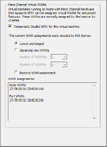
5. Repeat steps 1 and 2 to view the WWNs that were generated, as you can see in Figure 7.5.
6. Record the WWNs, and give them to your SAN administrator to properly zone Raw Device Mapping (RDM) LUNs that will be used by the guest.
7. To properly configure the guest WWN within your SAN zoning, refer to the appropriate SAN documentation provided by your SAN vendor.
Figure 7.4: Fibre Channel NPIV options
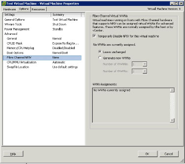
Figure 7.5: Generated WWNs
TIP If you want to use vMotion for a virtual machine that leverages NPIV, make sure to place the RDM file on the same datastore where the virtual machine’s configuration files are.
Before ESXi can work with an iSCSI SAN, you must set up your iSCSI initiators and storage. To do this, you must first observe certain basic requirements. This section discusses these requirements, provides recommendations, and then details how to provide access to the SAN by installing and setting up your hardware or software iSCSI initiators.
Become Familiar with ESXi iSCSI SAN Requirements
iSCSI storage has recently become a viable, cost-effective alternative to traditional Fibre Channel SANs.
TIP There are many iSCSI storage vendors on the market, so before choosing any particular vendor and product offering, ensure it is on the HCL. The VMware HCL can be found here: www.vmware.com/go/hcl.
When implementing an iSCSI SAN, keep in mind the following, as well as the items in “Guidelines for Implementing Storage,” earlier in this chapter:
- The network configuration for iSCSI initiators and the iSCSI storage system should reside on a network separate from host and guest IP traffic.
- Ensure hardware iSCSI initiators are compatible with vSphere ESXi hosts.
- Ensure the iSCSI target authentication scheme is compatible with the iSCSI initiator type.
Here are some network considerations:
- A best practice is to provide a dedicated network for iSCSI traffic between VMware hosts and iSCSI storage systems.
- To use software iSCSI, VMkernel networking must be configured.
- To use hardware iSCSI, the HBA has to have network parameters configured.
- The storage system discovery address must be pingable.
Configure Hardware iSCSI Initiators if Present
VMware ESXi supports dedicated physical iSCSI adapters installed in the ESXi host, provided they are certified and on the HCL. These physical adapters handle the iSCSI traffic in the same fashion as Fibre Channel HBAs do for Fibre Channel SANs. ESXi supports two types of hardware adapter:
Independent Hardware Adapters are capable of handling all iSCSI and network processing and management for ESXi.
Dependent Hardware Adapters depend on VMware’s networking and iSCSI configuration and management interfaces.
To get started, you must configure the hardware iSCSI initiator. When doing so, ensure that network settings are correct and that iSCSI names are formatted properly.
1. Log in to either vCenter Server or an ESXi host using vSphere Client.
2. Select a host from the Inventory panel.
3. Select the Configuration tab.
4. Select Storage Adapters in the Hardware panel.
5. Configure the desired initiator by clicking Properties and then Configure.
6. Accept the default iSCSI name or enter a new name. Properly format the name to ensure compatibility with your iSCSI storage systems.
iSCSI uses two different naming formats: iSCSI Qualified Name format (IQN) and the Enterprise Unique Identifier format (EUI). Determine which format you are using and follow that format’s guidelines for the iSCSI name.
7. Enter an iSCSI alias to be used to identify the hardware iSCSI initiator.
8. Change the IP address settings to be able to utilize the iSCSI storage network.
9. Click OK.
iSCSI name changes will only be valid for new iSCSI sessions. Any existing settings will remain until iSCSI logout and re-login.
Configure Software iSCSI Initiators
VMware ESXi can use iSCSI storage without the need for physical iSCSI adapters. The VMkernel can talk directly to iSCSI targets provided the software iSCSI initiator is enabled. To use this capability, you must complete some additional networking configuration.
First, you need to enable the iSCSI initiator. Follow these steps:
1. Log in to vCenter or an ESXi host with vSphere Client.
2. Select a server from the Inventory panel.
3. Click the Configuration tab, and then click Storage Adapters in the Hardware panel.
4. Click Add in the upper-right corner.
5. Select Add Software iSCSI Adapter and click OK.
6. Select the iSCSI initiator under Storage Adapters and click Properties from within the Details pane.
7. Click Configure at the bottom right of the window.
8. Check Enabled.
9. The iSCSI name will be automatically populated. If desired, you can enter a new iSCSI name. Properly format the name to ensure compatibility with iSCSI storage systems.
10. Click OK.
A VMkernel port and one or more physical adapters are required to use iSCSI storage via the software iSCSI initiator. The number of physical adapters you want to use will dictate the network configuration:
- If only one physical adapter is used, the only networking requirement is to configure a VMkernel port mapped to the single physical adapter.
- If two or more physical adapters are used, each adapter must have a separate VMkernel port mapped to leverage iSCSI multipathing. However, there can be only one active VNIC uplink for the portgroup. All others must be “unused.”
Create a VMkernel Port for Software iSCSI
A single VMkernel port can be used for communication with iSCSI targets. To configure the VMkernel port, follow these steps:
1. Log in to either the host or vCenter with vSphere Client.
2. Select the host from the Inventory panel.
3. Click the Configuration tab.
4. Click Networking.
5. Click Add Networking in the Virtual Switch view.
6. Select VMkernel and click Next.
7. Select Create A vSphere Standard Switch to create a new vSwitch, as shown in Figure 7.6.
Figure 7.6: Creating a virtual switch

8. If using a new vSwitch, select an adapter to use for iSCSI traffic.
9. Click Next.
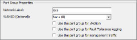
10. In the Port Group Properties section, enter a network label that will designate this VMkernel port, as shown in Figure 7.7.
Figure 7.7: Labeling the VMkernel port
11. Click Next.
12. Specify the IP settings, as shown in Figure 7.8, and click Next.
Figure 7.8: Entering IP settings

NOTE The network cards you are using with your iSCSI adapter must be on the same subnet (or have a layer 3 route to the iSCSI target) as your iSCSI target. Otherwise, your host will not be able to establish a session with the target.
13. Click Finish.
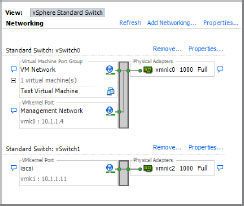
The network settings should appear similar to those in Figure 7.9.
Figure 7.9: Initial network settings
If only one physical adapter is going to be used for iSCSI traffic, configuration is complete. If more than one adapter is to be designated for iSCSI traffic, these steps may be repeated for the second adapter on a second virtual switch. Alternatively, additional VMkernel portgroups can be added on to the same vSwitch, so long as only one VMNIC is active per portgroup.
Configure Software iSCSI with Multipathing
Use this procedure if two or more network adapters are to be dedicated to iSCSI traffic and all the iSCSI network adapters are going to be connected to a single vSwitch. Each network adapter will be mapped to a single VMkernel port.
1. Log in to either the host or vCenter with vSphere Client.
2. Select the host from the Inventory panel.
3. Click the Configuration tab.
4. Click Networking.
5. Click Properties on the vSwitch being used for iSCSI.
6. Choose the Network Adapters tab, and click the add button at the bottom left to add one or more unclaimed network adapters to the vSwitch, as shown in Figure 7.10.
7. Click Next twice and then click Finish.
8. Ensure there is a VMkernel port for each physical adapter by viewing the Ports tab. If there are no distinct VMkernel ports for each network adapter, click Add, and follow the process described in the “Create a VMkernel Port for Software iSCSI” section earlier in this chapter.
9. At this point, all network adapters are active for all ports on the vSwitch. To map each adapter to a distinct VMkernel port:
a. Pick a VMkernel port, and click Edit.
b. Select the NIC Teaming tab.
c. Select Override vSwitch Failover Order.
d. Ensure only one network adapter is listed as active and all others (if any) are listed as Unused, as shown in Figure 7.11.
10. For each additional VMkernel port and network adapter, repeat step 1 through step 9 and choose adapters that are not assigned to other VMkernel ports. Figure 7.12 displays a configuration with two VMkernel ports using two network adapters.
Figure 7.10: Add Adapter Wizard

Figure 7.11: Mapping an adapter to a VMkernel port
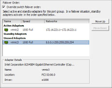
Figure 7.12: Two VMkernel ports using two different network adapters

Bind iSCSI Adapters with VMkernel Adapters
Now that we have the software iSCSI adapters enabled and the VMkernel ports created, we need to bind them together. Follow these steps:
1. From within vSphere client, click the Configuration tab.
2. Within the Hardware pane on the left side, select Storage Adapters.
3. Select the iSCSI adapter from within the Storage Adapters list and click Properties in the Details pane.
4. From within the iSCSI Initiator Properties screen, select the Network Configuration tab.
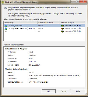
5. Click Add and select one of the VMkernel adapters to bind with the iSCSI adapter (see Figure 7.13). Click OK.
6. Repeat step 5 for any additional adapters you have.
7. Once you have added all of your adapters, click Close on the iSCSI Initiator Properties screen.
8. You should be prompted to rescan the host bus adapter. Click Yes.
Figure 7.13: Adding a VMkernel port to the software iSCSI initiator
Configure Jumbo Frames
Another consideration when using iSCSI storage is whether to enable jumbo frames. Jumbo frames are basically Ethernet frames that are larger than the standard 1,500 Maximum Transmission Units (MTUs). Jumbo frames can typically carry 9,000 bytes of data at a time. Therefore, they allow for bigger chunks of data to be transferred across an Ethernet network. To use jumbo frames, ensure that all devices on the network support them. vSphere supports jumbo frames up to 9,000 bytes, or 9 KB.
To configure jumbo frames on a vSwitch and VMkernel interface, follow these steps:
1. From within vSphere client, click the Configuration tab.
2. Within the Hardware pane on the left side, select Networking.
3. On the standard switch that you are using for iSCSI, click Properties.
4. On the Ports tab, select the standard switch and click Edit.
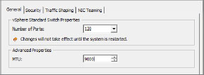
5. On the General tab in the Advanced Properties section, set the MTU size to match the largest MTU from among all NICs connected to the standard switch (see Figure 7.14). Click OK. You will need to consult the network card manufacturers’ documentation to determine maximum MTU size for each card.
6. On the Ports tab, select a VMkernel adapter and click Edit.
7. On the General tab in the NIC settings section, set the MTU to match the value set on the standard switch in step 5 above. Click OK.
8. Repeat step 6 and step 7 for all VMkernel adapters on the standard switch, which should have jumbo frames enabled.
Figure 7.14: Configuring jumbo frames on a vSwitch
Configure iSCSI Targets for VMFS Datastores
Now that the iSCSI initiators have been configured, the next step is to configure ESXi to see iSCSI targets for the purpose of remote storage. iSCSI targets must be discovered by ESXi. Two methods of discovery are available:
- Dynamic Discovery (also known as SendTargets)
- Static Discovery
Each has a configuration tab in the properties of hardware and software iSCSI initiators.
Before proceeding into the configuration, it is important to know the differences between Dynamic Discovery and Static Discovery.
Whenever an initiator contacts an iSCSI device, a SendTargets request is sent to the device and asks for a list of targets on the device. When devices are seen by ESXi, they are automatically listed on the Static Discovery tab. If these targets are removed from the Static Discovery tab, the next time a SendTargets request is sent, the target may reappear. When the host is using Static Discovery, iSCSI addresses do not have to be rescanned to see storage. No SendTargets discovery request is sent to the specified iSCSI device or devices. The initiator has a list of targets it can contact and uses their IP address and target names to communicate with them.
To set up Dynamic Discovery, take the following steps:
1. Log in to vCenter or a specific host using vSphere Client.
2. Select a server from the Inventory panel.
3. Choose Storage Adapters in the Hardware panel on the Configuration tab.
4. Select an iSCSI initiator and click Properties.
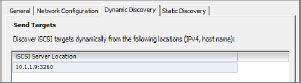
5. Click the Dynamic Discovery tab, as shown in Figure 7.15.
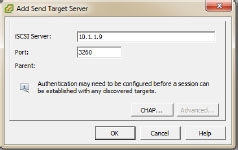
6. Click Add to add a new iSCSI device that will initiate the SendTargets communication, as shown in Figure 7.16.
7. In the Add Send Targets Server dialog box, enter the IP address or iSCSI name of the iSCSI device and click OK.
Figure 7.15: Dynamic Discovery tab
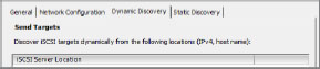
Figure 7.16: Initiating the SendTargets communication
Once successful communication has occurred between the initiator and the iSCSI device, the iSCSI server address will be displayed on the Dynamic Discovery tab, as shown in Figure 7.17.
Figure 7.17: iSCSI Server address is listed.
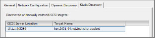
Additionally, any iSCSI storage targets discovered will appear in the Static Discovery tab. This is shown in Figure 7.18.
Figure 7.18: Discovered iSCSI targets are listed in the Static Discovery tab.
TIP If an address, iSCSI name, or port is added incorrectly, the connection will fail. To modify the entry, it must be deleted and re-added properly, as Dynamic Discovery targets cannot be modified. To remove a Dynamic Discovery server, select it and click Remove.
With iSCSI initiators, in addition to the Dynamic Discovery method, you can also use Static Discovery, where you manually enter the IP addresses and the iSCSI names of the targets to be contacted. To set up Static Discovery, follow this procedure:
1. Log in to vCenter or a specific host using vSphere Client.
2. Select a server from the Inventory panel.
3. Choose Storage Adapters from the Hardware panel on the Configuration tab.
4. Select an iSCSI initiator and click Properties.
5. Click the Static Discovery tab.
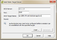
6. Click Add to add a new iSCSI target. Enter the IP address or DNS name in conjunction with the target device name, as shown in Figure 7.19.
7. Click OK to add the Static target.
8. To remove a target, select the target and click Remove.
Figure 7.19: Add Static Target Server
Static Discovery targets behave similarly to Dynamic Discovery targets in that they cannot be edited. If changes are required, the Static target will have to be removed and a new target added.
Configure CHAP Authentication
Unlike the Fibre Channel protocol, the iSCSI protocol does not limit physical devices to physical ports. With iSCSI operating over standard Ethernet, any device could potentially communicate with any other device on the same network. To address the situation where data is not protected between devices, the iSCSI protocol supports authentication. VMware ESXi supports Challenge Handshake Authentication Protocol (CHAP) for the purpose of securing iSCSI communications. CHAP authentication primarily uses a private value, known as a CHAP secret, to secure connections between iSCSI devices. This whole process can be simply described as password authentication. The hosts and the iSCSI targets must know the CHAP secret, or password, to be able to communicate with each other.
CHAP uses a three-way handshake algorithm to verify the identity of your host and, if applicable, of the iSCSI target when the host and target establish a connection. The verification is based on a predefined private value, or CHAP secret, that the initiator and target share.
When VMware ESX 3.0 was released, CHAP authentication could only be accomplished at the adapter level. This proved problematic if many different iSCSI devices were available to be used and they did not share a common CHAP secret. This remains true in VMware ESXi 5.0 with hardware-independent iSCSI initiators.
Using the software or dependent iSCSI initiator, however, VMware ESXi 5.0 not only supports CHAP authentication at the adapter level, but also at the level of each individual target. This addition provides VMware administrators with greater flexibility to communicate with many iSCSI targets that have one or more CHAP secret values. Table 7.3 displays the CHAP authentication levels supported by hardware and software iSCSI initiators.
Table 7.3: Adapter- and target-level CHAP authentication
| Initiator Type | Adapter-Level CHAP | Target-Level CHAP |
| Independent | Yes | No |
| Dependent | Yes | Yes |
| Software | Yes | Yes |
VMware ESXi 5.0 provides some additional levels of security and flexibility when hosts use iSCSI targets. With CHAP authentication, the authorization is only from the host to the iSCSI target. Mutual CHAP authentication has been added in vSphere to provide for two-way authentication between hosts and iSCSI targets. Not only does the host have to authenticate against the iSCSI target, but the iSCSI target has to authenticate with the host for data to flow between them. This provides for a more secure solution than simple one-way CHAP.
Additionally, CHAP authentication can be configured with some variable security levels that alter the behavior of authentication in securing data communications. Table 7.4 displays the different CHAP security levels.
Table 7.4: CHAP security levels
| CHAP Security Level | Behavior | Supported Initiators |
| Do Not Use CHAP | CHAP authentication is not used. This disables authentication. | Software, Dependent Hardware, Independent Hardware |
| Do Not Use CHAP Unless Required By The Target | The host prefers not to use CHAP but will use CHAP authentication as an alternative. | Software, Dependant Hardware |
| Use CHAP Unless Prohibited By The Target | The host prefers CHAP authentication but will use connections that do not have CHAP enabled. | Software, Dependent Hardware, Independent Hardware |
| Use CHAP | CHAP authentication is required. There will be no successful connections without CHAP authentication. | Software, Dependent Hardware |
When you configure CHAP settings, ensure that the iSCSI targets being used have the appropriate settings. Additionally, when you configure iSCSI targets, it is important to remember that the CHAP name and CHAP secret values are different for hardware and software iSCSI initiators:
Software iSCSI CHAP name has a 511-character limit and the CHAP secret has a 255-character limit.
Hardware iSCSI CHAP name has a 255-character limit and the CHAP secret has a 100-character limit.
When you are configuring CHAP authentication on iSCSI targets, plan accordingly to be able to accommodate software iSCSI initiators, hardware iSCSI initiators, or a combination of both.
NOTE Keep in mind that all discovery addresses or static targets inherit the CHAP parameters that are set up at the initiator level.
To configure CHAP authentication for iSCSI targets, begin with these steps:
1. Log in to vCenter or an ESXi host using vSphere Client.
2. Select a server from the Inventory panel.
3. Click Storage Adapters in the Hardware panel of the Configuration tab.
4. To configure a desired iSCSI initiator, select the initiator and click Properties.
5. On the General tab, click CHAP.
6. To configure one-way CHAP, do the following under CHAP:
a. For software iSCSI initiators, in the CHAP (Target Authenticates Host) section, select any of the options other than Do Not Use CHAP. If you want to configure Mutual CHAP, select Use CHAP.
b. Specify the CHAP name. Make sure that the name you specify matches the name configured on the storage side.
- To set the CHAP name to the iSCSI adapter name, simply select Use Initiator Name.
- To set the CHAP name to anything other than the iSCSI adapter name, deselect Use Initiator Name and enter a name in the Name field.
c. Enter a one-way CHAP secret to be used as part of authentication. Be sure to use the same secret that you enter on the storage side.
Figure 7.20 shows a one-way CHAP configuration in the CHAP Credentials window.
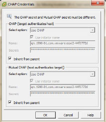
7. To configure Mutual CHAP, first configure one-way CHAP by following the directions in step 6. Be sure to select Use CHAP as an option for one-way CHAP. Then specify the following in the Mutual CHAP (Host Authenticates Target) section:
a. Select Use CHAP.
b. Specify the name or choose Use Initiator Name.
c. Enter the secret. Make sure to use different secrets for the one-way CHAP and Mutual CHAP.
Figure 7.21 shows a Mutual CHAP configuration in the CHAP Credentials window.
8. Click OK.
9. Rescan the adapter.
Figure 7.20: One-way CHAP configuration
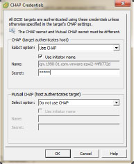
Figure 7.21: Mutual CHAP configuration

When CHAP and Mutual CHAP parameters are modified, they are only valid for new iSCSI connections. Any persistent connections will use the previous iSCSI credentials until you log out and log in again.
Set Up Per-Discovery and Per-Target CHAP Credentials
For software and dependent hardware iSCSI, you can configure different CHAP credentials for each discovery address or static target:
1. Log in to vCenter or an ESXi host using vSphere Client.
2. Select a server from the Inventory panel.
3. Click Storage Adapters in the Hardware panel of the Configuration tab.
4. Select the software iSCSI initiator and click Properties.
5. Select the Dynamic Discovery tab to configure authentication at the iSCSI storage system level.
6. From the list of available targets, select a target and click Settings, and then click CHAP. Figure 7.22 displays the CHAP Credentials screen with the default settings inherited from the software iSCSI initiator.
7. To configure one-way CHAP authentication, do the following in the section CHAP (Target Authenticates Host):
a. Deselect Inherit From Parent.
b. Select any of the options other than Do Not Use CHAP. If you want to configure Mutual CHAP, select Use CHAP.
c. Specify the name or choose Use Initiator Name.
d. Enter the CHAP secret for authentication. This must match the secret value on the storage side.
8. Mutual CHAP is configured only after CHAP is configured in the previous step. Specify the following under Mutual CHAP:
a. Deselect Inherit From Parent.
b. Select Use CHAP.
c. Enter the Mutual CHAP name.
d. Enter a Mutual CHAP secret. This secret value cannot be the same as the CHAP secret.
9. Click OK.
Figure 7.22: CHAP Credentials screen
Static Discovery targets can also be configured with independent CHAP and Mutual CHAP values by performing the following steps:
1. Click the Static Discovery tab, select an iSCSI target, and click Settings.
2. Click CHAP.
3. Perform steps 6 through 9 in the preceding list for each Static Discovery target that will be using CHAP or Mutual CHAP authentication.
4. Rescan the adapter.
If any CHAP or Mutual CHAP values change, they will be used for new iSCSI sessions. For existing sessions, new settings will not be used until you log out and log in again.
Create a New iSCSI VMFS Datastore
To add an iSCSI datastore, take the following steps:
1. From vSphere Client, choose a host from Inventory.
2. Select the Configuration tab, and then select Storage in the Hardware panel.
3. In the View panel, select Datastores.
4. Click Add Storage from the right side of the Datastores panel. The Add Storage wizard will open.
5. Choose Disk/LUN as the storage type and click Next. The right panel will display storage devices found after the HBAs were scanned.
6. Select a storage device and click Next. A review of the disk layout is displayed.
7. Click Next.
8. Enter a descriptive datastore name and click Next.
9. Choose Maximum Available Space. Click Next.
Choosing Maximum Available Space will use all of the available space on the LUN. It is a best practice to configure only one VMFS volume, or datastore, per LUN.
10. Click Next.
11. Click Finish to complete the datastore setup process.
The Network File System (NFS) protocol is another remote storage option supported by vSphere. As with iSCSI, NFS storage is accessed via an Ethernet network. Keep in mind that NFS storage is actually not a VMFS datastore, but rather a remotely mounted NFS export. Storage multipathing is not available with NFS storage. However, you do have the option of providing multiple VMNICs for the purposes of resiliency and portgroup load balancing.
Configure NFS Storage with ESXI
NFS-based storage has been around for approximately 25 years and several different versions have been released over that time. vSphere currently supports version 3, or NFSv3. Any device that provides storage using NFSv3 should work with vSphere, but to be certain, ensure the device is on the HCL. The VMware HCL can be found here: http://www.vmware.com/go/hcl.
When implementing NFS storage, keep in mind the following:
- Make sure the hardware and firmware versions are compatible with vSphere ESXi hosts.
- Storage vendor documentation should be consulted for additional NFS device configuration and host configurations.
- Eight NFS datastores are supported by default.
- A maximum of 256 NFS datastores can be mounted to an ESXi host.
- As with iSCSI storage, it is best to have a dedicated and secure Ethernet network for NFS storage, separate from host and guest IP traffic.
- In Windows virtual machines, increase the SCSI Timeout value parameter for better tolerance of I/O delays caused by path failover.
- ESXi does not restrict the size of the NFS datastore. The maximum size is determined by the NFS server.
- The use of non-ASCII characters is supported if the NFS server also includes international support.
Create a VMkernel Port to Connect to NFS Storage
For our example, the procedure for creating a VMkernel port to connect to NFS storage is identical to the steps for creating one for software iSCSI. For the step-by-step instructions, please refer to the earlier section “Create a VMkernel Port for Software iSCSI.”
NOTE There are different steps for configuring VMkernel portgroup load balancing for NFS if Ethernet cross-stack/802.3ad link aggregation is supported on the upstream switches. This procedure is beyond the scope this book.
Another configuration option to consider enabling when using NFS storage is jumbo frames. Jumbo frames also are covered in detail in the section “Create a VMkernel Port for Software iSCSI.”
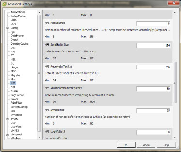
The default installation of vSphere supports a maximum of eight NFS datastores. You can use up to 256 NFS datastores if you modify the NFS.MaxVolumes parameter before attaching the first NFS datastore if needed. To change the maximum number of NFS volumes, follow this procedure:
1. Log in to either the host or vCenter with vSphere Client.
2. Select the host from the Inventory panel.
3. Click the Configuration tab.
4. Click Advanced Settings within the Software pane.
5. Click NFS in the left panel of Advanced Settings.
6. Scroll until the NFS.MaxVolumes setting is visible. (See Figure 7.23.)
7. Change the NFS.MaxVolumes setting to the number you want.
8. Click OK.
9. Reboot the ESXi host.
Figure 7.23: NFS.MaxVolumes setting
Attach a NFS Mount as a Datastore
NFS datastores are different from both FC and iSCSI VMFS volumes. The file system that the ESXi host uses is not a VMFS formatted file system. Also, there is no way to configure the amount of space that the host sees from vSphere Client without setting up an option like quotas on the NFS server. The space available to the host is configured on the NFS device. Follow these steps to add an NFS mount as a datastore:
1. From vSphere Client, choose a host from Inventory.
2. Select the Configuration tab, and then select Storage from the Hardware panel.
3. In the View panel, select Datastores.
4. Click Add Storage on the right side of the Datastores panel.
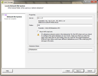
5. The Add Storage wizard will open. Choose Network File System as the storage type and click Next.
6. As shown in Figure 7.24, in the Server text box, enter the fully qualified domain name (FQDN) or IP address of the NFS storage device.
7. In the Folder text box, enter the name of the NFS export.
8. In the Datastore Name text box, enter the name of the datastore.
9. Click Next. A review of the NFS mount configuration is displayed.
10. Click Finish to complete the datastore setup process.
Figure 7.24: Mounting an NFS export
Script for Adding and Removing NFS Datastores
An alternative to working through the steps outlined in the “Attach a NFS Mount as a Datastore” section is to log in to the ESXi console and run an esxcfg-nas command similar to the example:
esxcfg-nas -a -o 10.1.1.9 -s /nfs nfs-datastore
The parameters in the example command work as follows:
-a adds a new NFS filesystem.
-o sets the host name or IP address.
-s sets the name of the share on the remote server.
If you are adding multiple NFS datastores, you can write a script to mount them all at once. You would then run this script across all hosts that need the NFS datastores. This is an easy way to ensure the datastore names are consistent across all hosts.
#!/bin/bash
esxcfg-nas -a -o 10.1.1.9 -s /nfs1 nfs-datastore1
esxcfg-nas -a -o 10.1.1.9 -s /nfs2 nfs-datastore2
esxcfg-nas -a -o 10.1.1.9 -s /nfs3 nfs-datastore3
To remove an NFS mount using the esxcfg-nas command, use the -d option, like this:
esxcfg-nas -d nfs-datastore
TIP It is important to note that the -d option does not delete the data on the remote NFS server. You are simply removing the NFS datastore from the ESXi host. By contrast, when you delete a VMFS datastore, the data will be lost.