Chapter 6
Creating and Managing Virtual Networking
IN THIS CHAPTER, YOU WILL LEARN TO:
- UNDERSTAND THE BASICS
- Work with Virtual Switches
- Understand Network Services
- Use NIC Teaming
- Configure VLANs
- Use VLAN Tagging
- View Networking Configuration and Network Adapter Information
- NETWORK WITH VSWITCHES
- Set Up NIC Teaming on the Management Network
- Assign Static IP Addresses for the Management Network
- Create a vSwitch for Virtual Machine Networking
- NETWORK WITH VSPHERE DISTRIBUTED SWITCHES
- Configure a vSphere Distributed Switch
- Add Hosts and Adapters to a vDS
- Edit General and Advanced vDS Settings
- Manage Physical and Virtual Network Adapters
- Migrate Existing Virtual Adapters into vDS
- Add a dvPort Group
- Edit a dvPort Group
- Create a Private VLAN
- Migrate VMs to a vDS
- UNDERSTAND ADVANCED NETWORKING
- Customize MAC Addresses
- Create VMkernel Ports for Software iSCSI
- Troubleshoot Using the Command Line
- Enable Cisco Discovery Protocol
- Enable IPv6
Four main resources combine to provide performance, stability, and flexibility in a virtualized environment: CPU, memory, storage, and networking. This chapter focuses on the fourth component: virtual networking. Networking ensures that the infrastructure is flexible in the way IP addressing is handled, provides stability because of the physical redundancy that can be built into the infrastructure, and aids in performance by making sure that adequate bandwidth is available for servers to use. In this chapter, we are going to define the key building blocks of virtualization and demonstrate how to set them up. We will also explore best practices for setting up your environment.
In a physical infrastructure, routers and switches are separate from servers but are connected with network cables. In a virtual infrastructure, this is still the case, but there are virtual switches (vSwitches) inside a host that virtual machines connect to in order to communicate with the external world. In many cases, several network adapters connect a host with outside physical switches. Virtual switches are the core building blocks of virtual networking and combine with physical network adapters to separate—and sometimes combine—traffic to provide performance, redundancy, and isolation of networking for security purposes.
Let’s start by exploring a virtualized infrastructure, starting with vSwitches. Then we will explore the network services that make up a vSwitch, learn how to physically set up redundancy on a vSwitch using NIC teaming, discover why VLANs are important to flexible networks, and learn how to view networking configurations.
Work with Virtual Switches
Virtual switches are internal to an ESXi host and allow you to network both traffic that is external to the host and traffic that never needs to leave the host (internal traffic). If virtual machines require a lot of bandwidth to communicate with one another, think about placing those VMs on the same host and sharing the same vSwitch. Internal traffic (two VMs internal to a host) has higher bandwidth capability than traffic that will hop multiple times across physical switches and network cables (outside of a host to another host or physical server). An example is when several VMs need to communicate with a database that is also on the same host and vSwitch.
You can add multiple physical network adapters to a single vSwitch to achieve additional bandwidth, balance communication routes, and provide greater redundancy that wouldn’t exist with just one adapter. By default there are 128 logical ports, and there’s a maximum of 4,096 usable ports on a single ESXi host.
Isolation of virtual LANs (VLANs) can be defined by adding port groups or by creating multiple vSwitches. Network labels, although not defined as a security boundary, either allow or prohibit VM portability across hosts using vMotion. Two or more hosts that have the same network will allow the use of vMotion.
Understand Network Services
A vSwitch can make two types of connections:
Virtual Machine This connection type is the most frequently used as it is the backbone for virtual networking.
VMkernel This connection type is used to handle host management, vMotion, Fault Tolerance, iSCSI, and NFS virtual networking.
NOTE ESX versions prior to vSphere 5 also included a Service Console connection type. This connection is replaced by the Management VMkernel port in ESXi, which is set up by default during a host installation. All management communication from the physical world to the ESX host traversed this connection.
Use NIC Teaming
The Management VMkernel connection is a great place to employ a strategy of NIC teaming. This is when more than one physical network adapter is associated with a single vSwitch to form a team. This is often configured on VMkernel ports to ensure that a single physical network failure does not disrupt an entire host. Not only can a team provide a failover path in the event of hardware failure, but both NICs can share the bandwidth load that exists between the vSwitch and the physical world (uplink load-balancing).
TIP NIC teaming can also be used on other types of network services.
Configure VLANs
VLANs are one of the most important aspects of virtual networking. Use of VLANs can enhance or diminish the capabilities of the virtual infrastructure. VLANs allow for a single physical LAN segment to be broken up into different broadcast domains. This strategy is most important to larger organizations that employ many different network segments for security and performance. If, for instance, an organization has 10 different VLANs, and if an ESX host needs access to those 10 VLANs, you can accomplish this in one of two ways:
Physical connections If you want your host to have access to all 10 VLANs, you could theoretically install 10 NICs and plug 10 network cables into the host. However, in reality, this isn’t always possible, and it’s often not the best use of resources. Additionally, if NIC teaming is to be used for redundancy, you’ll need a minimum of 20 network connections (two at a minimum for each of the 10 VLANs). Furthermore, if every host needs this same networking, soon your datacenter will be a cable management nightmare.
VLAN tagging Suppose VLAN tagging is used and each network cable is capable of carrying traffic from all network segments, each defined by a port group. In this example, fewer than 10 cables can be used. For example, you can use six network cables: two for the Management Network (which are NIC teamed), two for the vMotion VMkernel, and two for the last six VLAN segments carrying virtual machine traffic. As you can see, six cables are much easier to install and manage than a hypothetical 20 cables.
Use VLAN Tagging
VMware uses 802.1q for VLAN tagging, sometimes called trunking. This is a great way to set up a virtual infrastructure, as it allows for maximum flexibility with respect to networking. It is slightly more difficult to work with than regular one-for-one networking, but the added benefits that it brings far outweigh that small amount of extra work. VLAN tagging is also a godsend when network adapter ports are limited. For example, some blade servers may have a limited number. You may want to follow the VMware best practice and separate Management Network and vMotion traffic while still maintaining two physical NICs for failover and load balancing.
View Networking Configuration and Network Adapter Information
Before we start working, you need to locate where this work will be done—in other words, how and where to begin. From the vSphere Client, select the Host, select the Configuration tab, and finally select Networking.
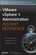
There is also another way to view information. Next to networking information are two types of icons that, if clicked, will display summary information for the object they represent. In basic networking, the icon looks similar to a small blue dialog box. (See Figure 6.1.) In the Distributed Virtual Switch view, the icon looks like a blue circle with the letter i in it. (See Figure 6.2.)
Figure 6.1: View summary networking information by clicking an icon.
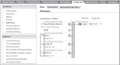
Figure 6.2: Summary information
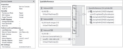
To view the network adapter information, from the vSphere Client click Host, select the Configuration tab, and then click Network Adapters (see Figure 6.3).
Figure 6.3: View networking adapter information
vSphere 4 and later support networking using third party vNetwork Distributed Switches (vDS) like Cisco’s Nexus 1000V and also maintain support for Standard vSwitches (vSS). vSwitches are easy to use and very functional. Let’s dive into using vSwitches and set up the Management Network, assign a static IP, and create a vSwitch for virtual machine networking.
Set Up NIC Teaming on the Management Network
The Management Network is one of the most important parts of an ESXi host, and it is one of the main forms of communication with an ESXi host. While virtual machines would continue to run and provide services without the Management Network, this would be similar to taking a cruise without a captain. Therefore, it makes sense to put extra effort into safeguarding its operation. One of the ways to accomplish this is to assign the Management Network two physical NICs; this approach ensures that if one NIC fails, communication with the host is not lost. Teaming two NICs keeps the High Availability service from assuming that the host is down, creating what is referred to as a split brain, and trying to restart the VMs on another host while they are still running on the disconnected host. Let’s take a look at how to team a network connection by adding an adapter and possibly adjusting which adapter is the primary.
1. From the vSphere Client, select Host, click the Configuration tab, select Networking, and then click Properties (next to the vSwitch where the Management Network resides).
2. Click the Network Adapters tab, click Add, and select an available VMNIC (as shown in Figure 6.4) (if none shows, there aren’t any available).
Figure 6.4: Adding unclaimed adapters
3. Click Next. You will see a screen with an option to reorder the adapters. Reordering the adapters is not relevant when using all in an Active fashion, so click Next again, and finally click Finish.
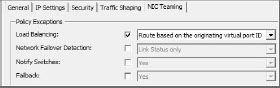
4. Click back to the Ports tab, highlight Management Network, and click Edit.
5. The Management Network Properties dialog box opens. Click the NIC Teaming tab, select the Load Balancing check box (as shown in Figure 6.5), click OK, and click Close.
Figure 6.5: Select the Load Balancing check box.
Assign Static IP Addresses for the Management Network
There are times when a DHCP address may have been used during multiple installations. If you need to change to static IPs, follow these steps:
1. From the vSphere Client, select the Host, click the Configuration tab, click Networking, and then select Properties (next to the vSwitch where the Management Network resides).
The default gateway for the VMkernel can be edited in the next step or from the DNS And Routing tab.
2. Highlight the Management Network, click Edit, click the IP Settings tab, and enter your information.
Create a vSwitch for Virtual Machine Networking
During installation you’ll notice an option to create virtual machine networking that is combined with the Management Network. Many administrators choose to turn off this option and/or separate virtual machine networking from the Management Network. This isolation ensures that the host is less likely to be open to attack if it is on the same network as other servers or, worse, end users.
In the following steps, we will create a vSwitch to separate the Management Network from virtual machine networking.
1. From the vSphere Client, highlight the host, click the Configuration tab, and under Hardware, choose Networking.
2. In the top-right corner, click Add Networking to open a window where you can choose a connection type. This is where you can create a VMkernel switch (used for vMotion IP storage, and host management). Regardless of the connection type, the remaining steps are similar.
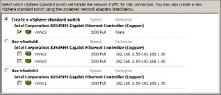
3. Choose Virtual Machine and click Next to reach a screen that will allow you to either create a new vSwitch or modify an existing one. You can also choose which physical NICs to associate with the vSwitch.
4. Make sure Create A Virtual Switch is selected, choose which VMNICs to use, and click Next (see Figure 6.6).
Figure 6.6: Creating a virtual vSwitch
Network Labels
Network labels are nothing more than labels given to a network connection. They do not define any technical aspect of that connection, except for the ability to enable VM portability (vMotion) across hosts. For example, if one connection is called “10.57.1” and on another host that same network connection is called “10.571” (missing the second dot), then there will be errors trying to vMotion across the hosts. Therefore, a simplified networking solution (when not utilizing vNetwork Distributed Switch [DVS]) ensures that the network labels are consistent.
Another naming strategy that many organizations utilize is a label that describes the IP network or VLAN number (if trunking). This accomplishes many things. First, it is easy to identify which network a virtual machine is part of based solely on the label. Second, if virtualization is used for disaster recovery solutions, the same naming strategy can be used when recovering virtual machines on replicated LUNs, eliminating extra steps during the recovery period. IPs will not have to be looked up for each virtual machine, and/or the same labels can be utilized in a recovery destination. The virtual machine networking will work without any manual adjustment to networking.
Port Groups
Port groups are an extremely useful part of networking because they allow you to define VLANs. Imagine a virtual infrastructure that utilizes several different VLANs but does not take advantage of trunking. As described earlier, in such a setup, each host may end up needing several network adapters in order to utilize the different VLANs in the infrastructure. Or worse yet, there might be several clusters in the infrastructure where only one IP network is defined per cluster. This setup can still be useful; however, it doesn’t make use of the power of the virtual infrastructure. In such a scenario, if virtual machines need to be moved to another cluster, their IP addresses must be changed. This is sometimes a challenge with applications and often requires some amount of downtime. When the hardware in a cluster is at the end of its useful life, all the virtual machines would need to be migrated. Another scenario that is challenging to negotiate with this setup is what to do if a smaller cluster has a host hardware failure and additional capacity is needed. In both situations, this setup is not as flexible as it could be.
Let’s now imagine a different setup. In this example, trunking is deployed and all hosts in the infrastructure have access to the different IP networks through VLAN tagging. This means that, from a network standpoint, any virtual machine can run on any host in the infrastructure regardless of cluster boundaries. If a host fails on any cluster, its virtual machines can be migrated to another host that has excess capacity. There is no need to run a few hosts at high CPU or memory levels, because all resources in the infrastructure can be shared without networking boundaries.
With respect to port groups, enter a number between 1 and 4,094 as assigned by the network team. If 4,095 is assigned, the port group can see traffic on any VLAN. If 0 is entered, the port group can only see untagged traffic (non-VLAN).
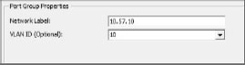
When setting up a network label for VLAN tagging, you will need to enter a port group in the VLAN ID field (see Figure 6.7). If you are not using VLAN tagging, leave this field blank.
Figure 6.7: Network label and VLAN ID
Add a VMkernel and Enable vMotion
In order to add vMotion capabilities, a VMkernel connection type must be added and configured, vMotion must be enabled, and the connection must be configured. A VMkernel connection can be added to a Management Network vSwitch or a vSwitch can be added that is separate from all other networks. Many administrators choose to add a VMkernel connection to the Management Network vSwitch and simply designate a different IP network to keep the communication distinct from other communication on the network. To do so, follow these steps:
1. From the vSphere Client, choose Host, click the Configuration tab, click Networking, and select the properties of the Management Network vSwitch.
2. Click the Add button in the bottom-left window and connection types will appear. Choose VMkernel and select Next.
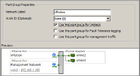
3. Enter an appropriate network label. In this case, the label vMotion is simple, easy, and descriptive.
4. Select the Use This Port Group For vMotion check box (see Figure 6.8).
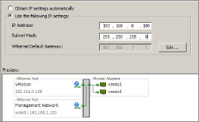
Figure 6.8: Enabling vMotion
5. Click Next.
6. Make sure the option Use The Following IP Settings is enabled, then enter a static IP address and subnet mask. (See Figure 6.9) In this scenario, the static IP address will be different from the Management Network IP network.
Figure 6.9: Configuring vMotion
7. Click Next, click Finish, and then click Close.
Network with vSphere Distributed Switches
The old-style vSwitch had to be configured exactly the same way on each and every host it was built on, which often caused issues if one check box or label was missed on any one host.
A vSphere Distributed Switch (vDS) is a consolidated switch that spans across hosts the administrator chooses. If there is a cluster or one or more hosts that don’t need that particular vDS, that vDS will not show up on those hosts. And because the vDS spans across the configured hosts, a virtual machine will be able to move consistently across the virtual infrastructure because the settings of that vDS are configured at the datacenter viewpoint. One of the great things about vSphere Distributed Switching is the ability to migrate existing vSwitches and/or connection types into a vDS and then centrally manage all networking through one interface.
The following list breaks down the vDS into easily digestible pieces:
dvUplinks Physical NICs plug into dvUplinks. The NICs can be renamed or left to the default. When creating the vDS, choose the maximum number of NICs that any one host in the switch will have. For example, if most of the hosts will have only two pNICs (physical NICs) but one will need four pNICs, then configure the vDS with four. On some, there will be unused dvUplinks, but that is not an issue.
Port Group A port group defines port configuration options such as teaming and failover, VLAN options, traffic shaping, and security. There may be more than one port group on any one vDS, and virtual machines may bind their vNICs (virtual NICs) to different port groups on the same vDS, depending on their needs or status in the organization.
Configure a vSphere Distributed Switch
In this section we are going to create a vDS where one did not exist before. Let’s take a look at how to accomplish this:
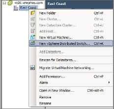
1. From the vSphere Client, at the top-left click Home, then under Inventory click Networking (Figure 6.10). Make sure your datacenter is highlighted, right-click it, and choose New vSphere Distributed Switch (see Figure 6.11) to launch the Create vSphere Distributed Switch Wizard.
Figure 6.10: Click Networking to begin.
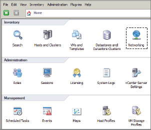
Figure 6.11: Creating a new vDS
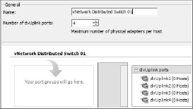
2. On the first screen (Figure 6.12), select the correct vDS version based on the lowest host version you wish to add to the vDS, and click Next. On the next screen (Figure 6.13), enter a descriptive name and specify the number of NICs in the Number of dvUplink Ports field, then click Next.
Figure 6.12: Selecting the vDS version
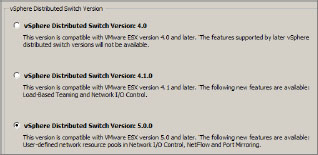
Figure 6.13: Naming the vDS
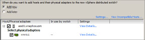
The next screen lets you add hosts and adapters to this vDS. In order to accomplish this, the NICs must be free.
TIP Note that additional hosts and adapters may be added at a later time. Take advantage of the View Details link to learn more about the physical NICs that are being added. Click the plus sign next to your hosts to see available NICs and their details.
3. Click Add Now (Figure 6.14) to add the hosts and adapters; then place a check mark beside the ones you want to add and click Next.
Figure 6.14: Adding hosts and adapters to your vDS
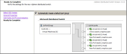
4. The next screen lets you create a default port group automatically (this is the default). If you leave this option selected, the vSphere Client will create an early-binding port group with 128 ports.
NOTE When viewing networking on any host, you have two options: vSphere Standard Switch or vSphere Distributed Switch (vDS). If the host is not part of a vDS, no options under vSphere Distributed Switch will appear. To get an overall view of all hosts on a vDS, check the Networking section in Figure 6.10 under Inventory.
Review the setup (see Figure 6.15), and click Finish.
Figure 6.15: Reviewing the current setup
Add Hosts and Adapters to a vDS
As your infrastructure grows, you may want to add more hosts to your vDS. You may also choose to add more adapters to address performance. Let’s look at this process:
1. From the vSphere Client, click Home, select Networking, highlight the vSphere Distributed Switch in question, right-click, and select Add Host.
2. On the next screen, select any additional hosts and NICs (see Figure 6.16), then click Next.
Figure 6.16: Adding hosts and adapters to a vDS
3. Review the selection, and then click Finish.
Edit General and Advanced vDS Settings
The General settings on the vSphere Distributed Switch Settings Properties tab (see Figure 6.17) allow you to change the name and number of dvUplink ports. To access the General settings from the vSphere Client, click Home, click Networking, highlight the vDS, right-click, and select Edit Settings.
Figure 6.17: Editing General and Advanced settings
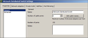
Click Advanced to access settings like MTU, Discovery Protocol, and admin contact information.
Manage Physical and Virtual Network Adapters
If you’re new to the vDS, and you may find yourself wondering how to manage the moving pieces. First, we’ll look at managing the physical adapters, and then we’ll move on to managing the virtual adapters.
Manage Physical Network Adapters
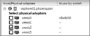
First let’s look at the process of managing physical network adapters:
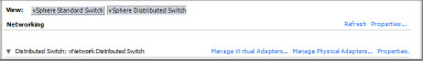
1. From the vSphere Client, select Host, choose the Configuration tab, click Networking, and select the vSphere Distributed Switch view (as shown in Figure 6.18). Then choose Manage Physical Adapters.
Figure 6.18: Here you manage virtual and physical adapters.
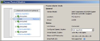
The resulting window lets you view the adapter and remove or add an adapter.
WARNING If you are adding a new adapter, it will remove that adapter from its current vSwitch. Be careful that the adapter being added is not currently serving virtual machines; also be aware of that adapter’s ability to service the Management Network IP network. Always think through your steps when working with physical adapters, and have a backup plan on how to access the host if you lose remote connectivity.
2. Highlight a NIC to access the physical details on it, and then choose Click To Add NIC or Remove (see Figure 6.19).
Figure 6.19: Reviewing the physical adapter’s details
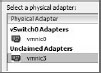
3. The Select A Physical Adapter window (see Figure 6.20) lists two types of adapters: adapters that are currently managed by other vSwitches and Unclaimed Adapters. Usually you will want to choose an unclaimed adapter. Highlight the adapter you want to add, then click OK twice.
Figure 6.20: Choosing unclaimed physical adapters
Manage Virtual Network Adapters
Now we will look at managing the virtual adapters:
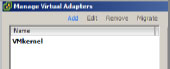
1. From the vSphere Client, select Host, choose the Configuration tab, click Networking, and select vSphere Distributed Switch view (as shown earlier in Figure 6.18). Then choose Manage Virtual Adapters.
The Manage Virtual Adapters screen lets you add virtual network adapters or migrate existing network adapters from the vSwitch side.
2. In the top-left corner, click Add (as shown in Figure 6.21).
Figure 6.21: Adding a virtual adapter
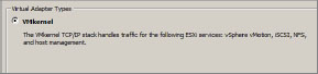
3. Select New Virtual Adapter and click Next.
4. Select VMkernel (refer to Figure 6.22), and then click Next.
Figure 6.22: Selecting the type of virtual adapter
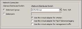
5. On the Connection Settings Screen, choose Port Group and then select the correct port. You can also use these options to enable vMotion, turn on fault tolerance logging, or create another Management Network connection (as shown in Figure 6.23).
Figure 6.23: Specifying the port group
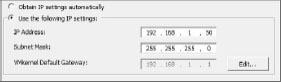
6. Make sure Use The Following IP Settings is selected, then enter the static IP settings (Figure 6.24).
Figure 6.24: Defining a static IP
7. Review the settings, click Finish, and then click Close.
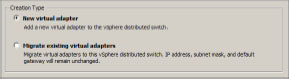
Migrate Existing Virtual Adapters into vDS
Why would you migrate existing virtual adapters into vDS? At the end of an upgrade process, you may find yourself with plenty of ESXi hosts that are all configured the same way, in the old vSwitch style, and you want to take advantage of central management. Or, you may want to get everything up and running in a format that is easier to understand and troubleshoot and, at a later time, make the move to vDS.
WARNING Before proceeding with migration, make sure the current physical NIC associated with this vDS is capable of communicating on the same network that the Management Network is connected to. At the end of this procedure, the Management Network is going to switch to a different physical NIC. If by chance communication is lost, try unplugging the original pNIC and plugging it into the pNIC that the vDS was plugged into. Then make your changes and start over. Keep in mind that in some cases this may not be easily accomplished, or perhaps not accomplished at all.
1. From the vSphere Client, select Host, click the Configuration tab, select Networking, click vSphere Distributed Switch, and choose Manage Virtual Adapters.
2. In the top-left corner, click Add (in blue lettering).
3. Select Migrate Existing Virtual Adapters, as shown in Figure 6.25. Then click Next.
Figure 6.25: Migrating existing virtual adapters
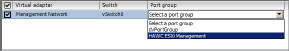
4. On the Network Connectivity screen, you’ll see a list of virtual adapters to migrate. Select Management Network.
Typically this list won’t be long since it is composed only of VMkernel adapters. There is also the option of migrating another adapter from a different vDS.
5. Click Select A Port Group to reveal the drop-down arrow and then select the port group to which this virtual adapter will be assigned, as shown in Figure 6.26. Then click Next.
Figure 6.26: Selecting a Port Group
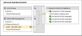
6. In the Ready To Complete screen, you will see a summary of the actions to be performed. Notice that the vmk0 (this is usually tied to the first virtual switch and it usually contains the Management Network), along with the IP address of the Management Network of that host, has been added (see Figure 6.27). Click Finish, and then click Close.
Figure 6.27: Reviewing the migration details
Notice that if the view in Networking is changed from vSphere Distributed Switch to vSphere Standard Switch, there is no longer an entry for the Management Network. However, as long as the port group you chose was set up correctly, communication with the host continues without interruption. Also notice that the pNIC originally associated with the Management Network on the vSwitch has not moved into the vDS.
Once everything is working, you may want to go back and move the original pNIC into this vDS for load balancing and failover of the Management Network. For details, see the section “Manage Physical Network Adapters” earlier in this chapter.
Add a dvPort Group
A dvPort group can span many hosts and is used to ensure configuration consistency for VMs and virtual ports such as vMotion. Additionally, a dvPort group defines port configuration choices for each port on a vDS by configuring how a connection is made to the physical network.
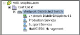
1. From the vSphere Client, select Home, select Networking, highlight the icon for vDS (in this case it is vNetwork Distributed Switch; see Figure 6.28), right-click, and select New Port Group.
Figure 6.28: Adding a dvPort group
2. Enter the name, number of ports, and VLAN type (as shown in Figure 6.29), and then click Next.
Figure 6.29: Configuring VLAN trunking
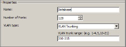
If VLAN Trunking is selected as the VLAN type, an additional option is available—VLAN Trunk Range. Enter the appropriate values for the trunked networks on the uplinked physical switch.
3. Review the settings, and then click Finish.
Edit a dvPort Group
The following steps illustrate how to edit dvPort groups:
1. From the vSphere Client, select Home, select Networking, highlight the dvPort group, right-click, and select Edit Settings.
2. In the next screen, you can modify the name, description, number of ports, and port binding (see Figure 6.30). Make your selections, and click OK.
Figure 6.30: Editing a dvPort group
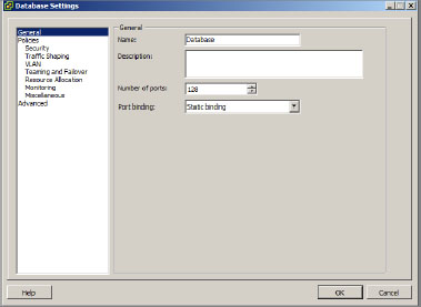
Here is a list of the port binding options and their purpose:
Static Binding Assign a port to a virtual machine when the VM is connected to a dvPort group. This is the default binding type.
Dynamic Binding Assign a port to a virtual machine on the first power-on while in the dvPort group.
Ephemeral Choose this option when there is no port binding. This is the same binding type as the standard vSwitch.
NOTE If you’re running vCenter or any of its dependent services, like a database server, as a virtual machine within your vSphere environment, you’ll want to choose the Ephemeral port binding type for the dvPort Group where your VM is attached. This will avoid a “chicken & egg” scenario when the VM is rebooted and allow it to connect to the dvPort before the vCenter service starts.
Create a Private VLAN
With private VLANs, you can restrict communication between VMs even when they are on the same VLAN or network segment. Let’s take a look at how to accomplish this and create a private VLAN:
1. From the vSphere Client, select Home, select Networking, highlight the DVS you want to work with, right-click, and select Edit Settings.
2. Select the Private VLAN tab; under Primary Private VLAN ID, click Enter A Private VLAN ID Here, and enter the VLAN ID number. Then click elsewhere in the window.
3. Highlight the VLAN ID just entered and it will show up under Secondary Private VLAN ID.
4. Under Secondary Private VLAN ID, enter the information in Enter A Private VLAN ID Here as before (as shown in Figure 6.31).
Figure 6.31: Creating a private VLAN
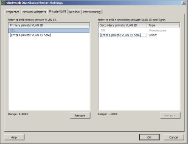
5. Highlight the secondary private VLAN you just added and select the port type. When finished, click OK.
Following are the port types available:
Promiscuous Port Communicates with all other private VLAN ports.
Isolated Port Has Layer 2 separation from other ports within the same private VLAN, with the exception of the promiscuous port.
Community Port Communicates with other community ports and transmits traffic outside the group via the designated promiscuous port.
Migrate VMs to a vDS
There are two ways to migrate virtual machines into a vDS. The virtual machines network adapter settings can be changed to reflect the new settings, or you can use a VMware migration tool to move a group of virtual machines all at one time. This tool is granular enough to allow you to pick which virtual machines to move now and which to move at a later period, or not at all. The following process demonstrates the migration tool:
1. From the vSphere Client, click Home, select Networking, highlight the vSphere Distributed Switch, right-click, and select Migrate Virtual Machine Networking.
2. From the Source Network drop-down list, choose the location of the existing virtual machines.
3. From the Destination Network drop-down list, choose the location where the virtual machines will be migrated to.
4. Click Next to view the Select Virtual Machines window.
5. Put a check mark next to the virtual machine adapters that need to be moved and click Next (see Figure 6.32).
Figure 6.32: Migrating VMs to vDS
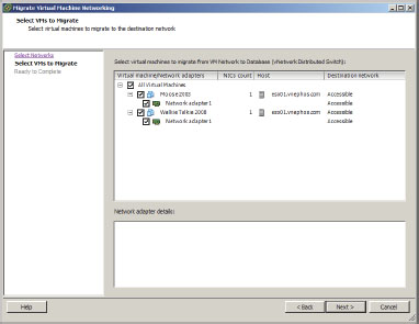
6. Review the migration summary and click Finish.
To migrate an individual virtual machine (without using the tool) into a vDS, edit the settings of the VM and simply change the network adapter settings (under Network Label) to reflect the location they will be migrated to.
Understand Advanced Networking
There are day-to-day networking activities, and then there are advanced networking topics. These are the features that help us add more functionality, help us troubleshoot, or help us grow. Take, for example, the topic of customizing MAC addresses; this is clearly networking but not something that needs to be done on a regular basis. However, it may help you provide a software-based key for some specific applications while avoiding a hardware key (think USB dongle). Let’s take a look at this and other advanced networking topics.
Customize MAC Addresses
In what instances would you customize MAC addresses? There are more than a few applications out there that require some sort of license file to work, and some of them bind to the MAC address on the server. In some cases, it is possible to get a software vendor to give out a software-based license instead of a hardware-based USB key; but they will only do this for a vigilant and determined VMware administrator who won’t take no for an answer. Virtual machines by default do not have static MAC addresses; therefore, if one is needed it must be assigned.
TIP Do not change the MAC address unless it is absolutely necessary. Instead, let the software do what it does best and avoid unnecessary complexity.
The allowable range for MAC addresses is from 00:50:56:00:00:00 to 00:50:56:3F:FF:FF. The last 3 bytes are configurable. Keep it simple; make the first static MAC address 00:50:56:00:00:01. Here’s how:
1. From the vSphere Client, select the virtual machine and click Edit Settings.
2. On the Hardware tab, highlight the network adapter. On the right there will be a MAC address that can be changed from Automatic to Manual.
Unfortunately, the colons will need to be typed into the interface; it isn’t intelligent in this respect.
3. Enter the desired MAC address, document it (so you have it for later reference), and click OK.
Create VMkernel Ports for Software iSCSI
Some installations use Fibre Channel SAN, and others use iSCSI, which traverses Ethernet. In this section we will look at the prerequisites for using iSCSI and then show you how to set it up.
In previous versions of vSphere, binding VMkernel ports to the iSCSI Software Adapter could only be completed via the command line. In vSphere 5, VMware added this functionality to the vSphere Client GUI.
NOTE Redundancy and load balancing for the iSCSI Software Adapter are provided by multiple VMkernel ports rather than by adding multiple physical NICs to the vSwitch where the iSCSI VMkernel resides. Therefore, one of the prerequisites for Software iSCSI port binding is that an iSCSI VMkernel port must have exactly one active physical uplink and no standby uplinks.
First we are going to create new VMkernel ports, and then we will bind the iSCSI Software Adapter to them:
1. From the vSphere Client, click Host, select the Configuration tab, click Networking, select the vSwitch view, and click Add Networking.
2. Select the VMkernel, and then click Next.
3. Choose Create A vSphere Standard vSwitch.
a. Put check marks next to the network adapters to be used with this switch and click Next.
b. Choose an appropriate network label.
c. Add the VLAN ID if one exists and click Next.
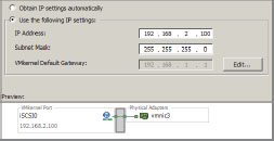
4. Make sure Use The Following IP Settings is selected, then enter the IP address information (see Figure 6.33). Then click Next.
Figure 6.33: iSCSI connection type
5. Finally, click Finish.
The VMkernel port has now been created. Our next step is to override the switch physical NIC failover order for the iSCSI VMkernel interface we just created:
1. From the vSphere Client, click Host, select the Configuration tab, click Networking, select the vSwitch view, and click Properties beside the vSwitch we just created.
2. Select the iSCSI VMkernel portgroup just created and click Edit.
3. On the NIC Teaming tab, select the check box labeled Override Switch Failover Order. This overrides the physical NIC failover order so that only one VMNIC is active.
4. Click the second VMNIC listed under Active Adapters.
5. Click Move Down until this VMNIC is under Unused Adapters. (See Figure 6.34)
Figure 6.34: Override physical NIC failover order
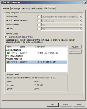
6. Finally, click OK.
Now that the first iSCSI VMkernel interface is configured to use only one physical NIC, we must create a second iSCSI VMkernel interface for redundancy and load balancing:
1. From the vSphere Client, click Host, select the Configuration tab, click Networking, select the vSwitch view, and click Add Networking.
2. Select the VMkernel, and then click Next.
3. Choose Use vSwitch (the vSwitch you created in the steps above). Choose an appropriate network label and add the VLAN ID if one exists. Then click Next.
4. Enter the IP address information, then click Next.
5. Finally, click Finish.
The second iSCSI VMkernel port has now been created. Our next step is to override the switch physical NIC failover order for the second iSCSI VMkernel interface. We’ll use the opposite active and unused adapters configured for the first iSCSI VMkernel interface:
1. From the vSphere Client, click Host, select the Configuration tab, click Networking, select the vSwitch view, and click Properties beside the vSwitch we just created.
2. Select the second iSCSI VMkernel portgroup just created and click Edit.
3. On the NIC Teaming tab, select the check box labeled Override Switch Failover Order.
4. Click the second VMNIC listed under Active Adapters.
5. Click Move Down until this VMNIC is under Unused Adapters. (See Figure 6.35)
Figure 6.35: Override physical NIC failover order
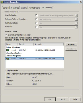
6. Finally, click OK.
We can now enable and bind the iSCSI Software Adapter to the VMkernel ports we just created. See Chapter 7, “Configuring and Managing Storage.”
Troubleshoot Using the Command Line
Occasionally networking can be misconfigured, due to scripts not working properly, physical NICs being configured with the wrong network, or a whole host of other reasons. Being able to navigate via the command line while standing in front of the ESXi host may be the only way to get the infrastructure back in tip-top shape. Table 6.1 presents some commands that are used to accomplish just that.
NOTE If communication with an ESXi host is not possible, step up to the host console, log in to the DCUI by pressing F2, navigate to Troubleshooting Options, enable the ESXi shell, and then press Alt+F1.
Table 6.1: Handy command-line tricks
| Command | Description |
| esxcfg-vmknic -l | Provides a list of the VMkernel network interfaces. Make sure that vmk0 is defined and that the current IP address and netmask are accurate. |
| esxcfg-vswitch -l | Provides a list of the current vSwitch configurations. Ensure that the uplink adapter configured for the Management Network is connected to the correct physical network. |
| exscfg-nics -l | Provides a list of the network adapters. |
| Check that the uplink adapter assigned to the Management Network is up and that the speed and duplex are both accurate. | |
| esxcfg-nics -s <speed> <nic> | Changes the speed of a network adapter. |
| esxcfg-nics -d <duplex> <nic> | Changes the duplex of a network adapter. |
| esxcfg-vmknic -a -i <new ip address> -n <new netmask> -p <portgroup name> | Adds a new VMkernel interface with the parameters specified. Note that a portgroup must be created prior to adding the VMkernel interface. |
| esxcfg-vmknic -d <existing portgroup name> | Removes a VMkernel interface from the specific portgroup. |
| esxcfg-vswitch -U <old vmnic> <Management Network vswitch> | Removes the uplink for the Management Network. |
| esxcfg-vswitch -L <new vmnic> <Management Network vswitch> | Changes the uplink for the Management Network. |
If there are long delays when using esxcfg-* commands, DNS might be misconfigured. The esxcfg-* commands require that DNS be configured so that localhost name resolution works properly. This requires that the /etc/hosts file contain an entry for the configured IP address and the 127.0.0.1 localhost address.
Enable Cisco Discovery Protocol
Cisco Discovery Protocol (CDP) allows an ESXi host to determine which Cisco switch port is connected to a given vSwitch and will allow properties of the Cisco switch to be viewed from the vSphere Client. Obviously if Cisco hardware is not part of the organization, this procedure is not necessary or advised. This process requires logging directly into the ESXi command-line interface.
NOTE In vSphere 5, VMware added the ability to enable both CDP and LLDP (for non-Cisco branded switches) on vSphere Distributed Switches using the vSphere Client GUI. The settings can be found under the Advanced section of the Properties tab of the vDS.
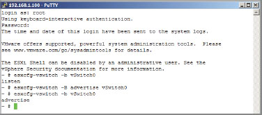
After the ESXi console or SSH has been enabled using the DCUI Troubleshooting Mode, log into the host. Remember that the command line is case sensitive, and in the next step, the S in vSwitch must be uppercase and the -b must be in lowercase.
esxcfg-vswitch -b vSwitch0
The listen mode is the default. Possible outcomes are outlined in Table 6.2.
Table 6.2: Cisco Discovery Protocol modes
| Mode | Outcome |
| down | CDP is disabled. |
| listen | ESXi listens for information but doesn’t return information. |
| advertise | ESXi sends information but doesn’t gather information. |
| both | ESXi listens and sends information. |
To switch modes, enter the following command. Note that the -B is now uppercase. If the organization does not have CDP or LLDP compatible switch hardware, change mode to down.
esxcfg-vswitch -B <mode> vSwitch0
Figure 6.36 shows the available commands.
Figure 6.36: Working with Cisco Discovery Protocol
Enable IPv6
IPv6 is set to replace IPv4 because there are not enough IP addresses under the old method. You can run IPv6 in a mixed environment with IPv4. It uses a 128-bit address and all features are capable of running under this protocol. Here’s how to enable IPv6:
1. From the vSphere Client, select Host. On the Configuration tab, choose Networking.
2. Choose Properties in the top-right corner of the next window.
3. Select Enable IPv6 Support On This Host and then click OK (see Figure 6.37).
Figure 6.37: Enabling IPv6
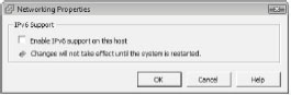
4. Reboot the host to let the changes take effect.