
Chapter 5. Telephony Hardware Hacks
Hacks 59–71: Introduction
One of the reasons VoIP is such a positive evolutionary step for telecommunications is that it employs a highly distributed, software-centric design philosophy. It has the extensibility and programmability of the Internet, putting telephony power back into the hands of the users, not the phone companies. It is programmability—software—that makes IP telephony such a killer application.
Yet, critical parts of voice telecommunications are entirely in the domain of hardware. This chapter focuses mainly on hardware hacks: projects with a decidedly piquant, earthy flavor; projects that deal with analog telephone adapters (ATAs), phone line gateways, and “bat phones.” You won’t need much in the way of ‘l33t coding skills, but you’ll use some basic Perl. Have some Ethernet patch cables and Velcro handy. Oh, and it might help to have a bottle of XML on ice if the mood is right.
In this chapter, you’re going to be looking at VoIP and legacy telephony hardware—everything from state-of-the-art Internet Protocol (IP) phones to vintage rotary-dial candlestick phones—and how to get them working together. You might also pick up some handy tips for your cell phone, as well.
Record Calls the Old-Fashioned Way
Digital and IP phone handsets are analog inside, which means you can use a transducer microphone to record a phone call.
It’s fairly easy to record from a standard telephone using an inline recorder switch. These devices allow you to record the analog audio signal on a standard Plain Old Telephone Service (POTS) line or a handset-to-deskset line using an analog recording device like a microcassette recorder or a personal dictation recorder. An easy way to use one of these recorder switches to produce a digital recording of a call is to connect the mono audio output to your computer’s microphone line-in.
Most of these switches (such as Radio Shack’s model 43-1237) offer a 1/8-inch male audio connector, which is perfect for use with a PC sound card or a Mac line-in, which both tend to be 1/8-inch female connectors. Just plug the recorder switch into the phone line and your computer’s audio input, and you’ve got an instant call recorder in the form of your favorite audio recording program (such as Windows Sound Recorder).
Since inline recorder switches work only with analog lines, you can’t use them to record calls on digital or IP telephones. If you want to use your PC to record from these devices, you’ll need something a little more James Bondish, like a transducer pickup. This is a microphone that you stick to the outside of your telephone handset, on the back of the receiver, that is sensitive enough to record the audio inside the handset. Since even digital and IP telephones use purely analog handsets, a transducer pickup can record them all. Some pickups (such as Radio Shack’s model 44-533) include a built-in suction cup that adheres easily to the handset. Like a recorder switch, these pickups provide a 1/8-inch mini plug that you can mate with your sound card’s audio line-in jack to make digital recordings.
Warning
Recording phone calls can get you in trouble unless all parties on the call are aware that the call is being recorded. Check your local laws before recording any phone calls.
See Also
“Record VoIP Calls on Your Windows PC” [Hack #13]
“Record an Audio Chat on Your Mac” [Hack #23]
Make IP-to-IP Phone Calls with a Grandstream BudgeTone
With minimal effort, Grandstream’s BudgeTone series of IP phones can make and receive calls on your network—even without a PBX server.
In most enterprise VoIP setups, you have a PBX that connects all of the phones on the network. The PBX acts as a centralized signaling authority and access-control server for all of the telephone users. But some IP phones don’t need a PBX at all. They can call each other directly by way of an IP address. You’re about to make a direct IP-to-IP call with a BudgeTone hardphone.
Tip
A hardphone is an IP phone that isn’t a softphone. It looks just like an ordinary business phone, but plugs directly into an Ethernet local area network (LAN).
The Grandstream BudgeTone 100 phone model has a Menu key, an LCD display, and two arrow keys that you use to navigate its configuration menu options: DHCP, IP Address, Subnet Mask, Router Address, DNS Server Address, TFTP Server Address, Codec Selection Order, SIP Server Address, and Firmware Versions (called Code Rel on the phone’s screen). When you get to the option you want, you press the Menu key to select it, and then enter the numeric data required for each option using the keypad. Use this menu only to set up the IP address, subnet mask, and router (default gateway) address, because you’ll be doing the rest of the phone’s configuration using its web interface.
To get the phone enabled for the next configuration step, turn DHCP off and assign an IP address, subnet mask, and router address.
You can perform more advanced configuration using the BudgeTone’s built-in web configuration tool. When you use your web browser to access the IP address you assigned, you’ll be prompted to log in to the phone. The default password is admin.
Then, you’ll be confronted with a big page of configuration options, many of which are available only through this interface, not from the phone’s keypad metu. For this project, the only settings we’re concerned with are the codec selection ones. Configure the first (highest-priority) codec to be "PCMU” if you’re in North America or "PCMA” if you’re elsewhere in the world. That’s all we’re going to cover about codecs for now. After you apply any configuration changes, you need to power-cycle the BudgeTone.
Some IP phones offer a Telnet interface rather than a web-based one. To use these tools, you must connect to the phone with a Telnet client rather than a web browser. In any event, once the network configuration is set on the IP phone, ping its address from another host on the same network subnet to make sure it’s speaking Transmission Control Protocol/Internet Protocol (TCP/IP).
Tip
Many VoIP devices need access to a time clock. The network time protocol (NTP) server we’ve chosen is time.nist.gov. More NTP servers are available from the list at http://www.nist.gov/.
Make an IP-to-IP Phone Call
With both IP phones connected to the same Ethernet switch, or directly connected (to each other) using a crossover patch cable, make a note of the IP address you’ve established for each. In this example, we’ll use 10.1.1.103 for the receiver and 10.1.1.104 for the caller. If you have your phones configured for DHCP, give them this static configuration instead.
The BudgeTone can place IP telephone calls from one IP endpoint directly to another without the need for a VoIP call-management server. This is known as IP-to-IP calling. Since each IP phone has a unique identification characteristic within the scope of the network—an IP address—one phone can call the other by IP address as if it were a phone number.
Now, to dial by IP address. All IP addresses are 12 decimal digits long, even if preceding zeros aren’t visible when notated. Conversely, the dots (.) that are normally included in a notated IP address are not dialed. So, on the BudgeTone phones, 10.1.1.103 is dialed as:
010 001 001 103
To dial, take the phone off the hook so that you hear a dial tone, and then press the Menu key, dial the address of your second phone according to the convention just shown, and press the Send or Redial button. Of course, nobody would want to dial 12-digit IP addresses to place phone calls all the time; call management servers, like Session Initiation Protocol (SIP) registrars, provide more elegant dialing conventions. However, dialing by IP address does allow you to circumvent call management and make a direct VoIP connection between two endpoints.
When the receiving phone rings, have somebody answer the call. If you can hear them talk through your IP phone’s handset, you’ve just made your first successful VoIP phone call—sort of the IP equivalent of Bell and Watson’s first phone call back in 1876.
If the receiving phone doesn’t ring, you might have to check the IP address you dialed, check the phone’s configuration to make sure it is listening on the default port for SIP—5060—and make sure SIP registration is turned off. These options concern the Grandstream’s use with a PBX server, which isn’t a factor in this case.
Mounting the Grandstream on the Wall
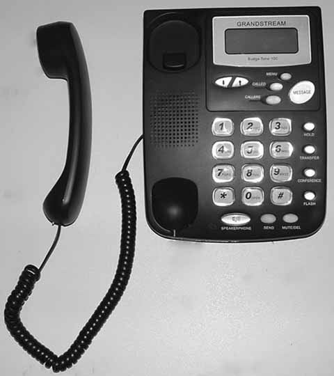
For practical, day-to-day use, Grandstream, shown in Figure 5-1, has a few shortcomings. At the top of my “bug list” for the Grandstream 101 is its half-baked support for being hung on the wall (in addition to sitting flat on the desktop). I say half-baked because Grandstream provides screw holes for hanging the phone on the wall, but it doesn’t provide a notch to keep the handset on the phone when it’s hanging. So, the handset just slips off the phone when you attempt to set it upright.
This won’t do. I’ve envisioned two ways to deal with this problem. First, you can go the Velcro route. Apply about a square centimeter of Velcro adhesive hook strip to the handset, at the point where a normal wall-hanging handset’s notch would be. At the corresponding position on the phone itself, put the same amount of Velcro latch strip so that when you hang up the handset, it actually stays in place.
The second way to deal with the wall-hanging problem, which is probably a longer-lasting or more durable approach, is to drill a small hole in the phone base at the point where the wall-hanging notch should be. The hole should be about one-third of an inch to three-quarters of an inch in diameter. Then, again, at the corresponding spot on the handset, screw into the plastic casing a very short, round-headed screw. The head of the screw, if small enough to fit into the hole you drilled, should keep the handset firmly latched onto the phone’s base. Not pretty, but it works.
Build a Custom Ringtone for Your Grandstream Phone
Sure, your cell phone has a custom ringtone, but does your IP phone? With a little help from Perl, you’ll able to load any sound you like onto the Grandstream phone.
If you carry a cell phone, you’ve no doubt changed your ringtone once or twice. From a sample of a vintage mechanical ringer to a recording of a C-3PO line from Star Wars, ringtones have become central to pop-culture communication. So why can’t you customize the ringtone on a Grandstream IP phone, one of the cheapest and most popular SIP hardphones available?
Well, since you asked, you can. It just takes a little hack job.
The Grandstream’s firmware stores the ringtone in its own odd format, a uLaw sound file with a custom header at the beginning of it. It’s simple enough to make a uLaw sound file; just use SoX [Hack #24] . But to add the header, a little Perl magic is needed.
The Code
This script was written by Tony Mountifield, and its purpose is to create a Grandstream-compatible ringtone file:
	#!/usr/bin/perl
	$filename = shift or die "need output filename
";
	undef $/; # slurp whole file at once…
	$audio = <>; # … like this
	$filesize = 512 + length $audio;
	if ($filesize & 1) {
		# length odd, add a zero byte (should never happen)
		$audio .= chr(0);
	}
	die "Audio file too large
" if $filesize > 65536;

	# this is the format for the header
	$headerfmt = "n n n C4 n C C C C a22 n x216 n n x36 a216";

	# get the current date and time
	($min, $hour, $day, $month, $year) = (localtime)[1..5];
	$year += 1900;
	$month += 1;

	# create the header, with zero for the checksum
	$header = pack $headerfmt,
			0, # 0000
			$filesize/2,
			0, # put checksum in later
			1,0,0,1, # version
			$year, $month, $day, $hour, $min,
			$filename,
			0,		  # 0000 or 00C8 - why?
			256,		# 0100
			$filesize/2,
			"Grandstream standard music ring";

	# sanity check
	$headerlen = length $header;
	die "header length wrong ($headerlen)
" unless $headerlen == 512;

	# add the audio
	$header .= $audio;

	# compute the checksum
	$checksum = unpack "%16n*", $header;
	#printf "checksum before = %04x
", $checksum;

	# insert it in the correct place
	substr($header,4,2) = pack "n",-$checksum;

	# ensure the new checksum is zero
	$checksum = unpack "%16n*", $header;
	#printf "checksum after = %04x
", $checksum;
	die "checksum failed
" unless $checksum == 0;

	# write the file
	open F, ">$filename" or die "can't open output file $filename: $!
";
	print F $header;
	close F;
Running the Code
To use this program, save it as makering.pl, make it executable (chmod 755 makering.pl), and pipe a uLaw sound file into it in a shell, like so:
$ sox my_sound -r 8000 -c 1 -t ul - rate | makering.pl ring1.binIn this example, the file my_sound will be resampled to 8000 Hz and will be piped in uLaw format to the standard input of makering.pl, which is the Perl script shown earlier. The enhanced output is then saved as ring1.bin. Upload this file to the /tftpboot directory of your Grandstream’s TFTP server and then reboot your Grandstream. (For some tips on setting up a TFTP server, see “Make IP Phone Configuration a Trivial Matter” [Hack #80] .) With a fun new ringtone, your IP phone is now as cool as your cell phone.
Tweak Your Sipura ATA
If you own a Sipura ATA, you’ve got a veritable softPBX hiding in that slick plastic enclosure. If only you knew how to set it up!
Sipura Technology, now a division of Cisco, makes some very powerful telephony devices. With hundreds of options and many potential combinations, literally thousands of possible configurations are available. While I can’t cover them all here (for obvious reasons), I can give you a few examples to get your mind working.
Configure the Sipura by Dialing
Sipura’s line of products has a powerful interactive voice-response (IVR) system built in that gives you administrative access to many of the ATA’s features. In fact, the IVR will probably be one of your first experiences with Sipura’s ATAs. The IVR (like the web interface) has quite a few options. Thankfully, Sipura publishes a user guide that details all of the available options in the IVR menu, as well as in the web configuration screens. In fact, so many options are available that the user guide was 87 pages long at the time of this writing! You can find this document in the Support section of http://www.sipura.com/.
After unpacking the Sipura and connecting the cables, you should pick up your phone and dial ****. This will connect you to the Sipura Configuration Menu. You will be asked to enter an option. But what option to enter? Table 5-1 will get you started.
|
Option name |
Option name |
Valid options |
Notes |
|
DHCP status |
100 |
None |
|
|
Check IP address |
110 |
None |
Reads current IP |
|
Set static IP address |
111 |
IP address; enter IP, using * to input periods |
|
|
Check network mask |
120 |
None |
|
|
Set network mask |
121 |
Same as Set static IP address |
|
|
Check gateway IP |
130 |
None |
Reads current IP |
|
Set gateway IP address |
131 |
Same as Set static IP address |
|
|
Check DNS server |
160 |
None |
|
|
Set DNS server IP address |
161 |
Same as Set static IP address |
|
|
User” reset |
877778 |
None |
Resets all of the “user-changeable” settings to their defaults. Use with caution! |
|
“Factory” reset |
73738 |
None |
Resets all of the available configuration options to their defaults. Use with caution! |
Remember to add a trailing # for each option. So, for example, to have the Sipura read its current IP address, you should enter **** and then 110#. Another thing to remember: when you are entering IP addresses for the device, default gateway, and DNS server, use the * key to represent periods (.). So, you’d enter the IP address 10.1.1.50 as 10*1*1*50#.
Various Tweaks
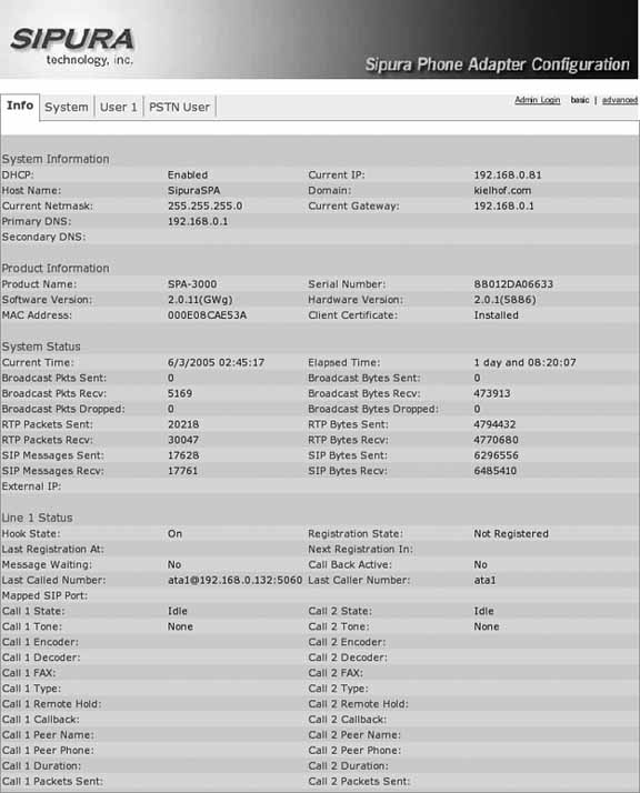
After you have the Sipura connected to your network and you know its IP address, you can get to its web interface. If you’re used to dealing with web interfaces for Network Address Translation (NAT) firewalls and the like, the Sipura web interface, shown in Figure 5-2, is probably unlike anything you’ve seen. Most people that use the web interfaces of small-office/home-office (SOHO) NAT/firewall/router devices are shocked when they see the web interface on a Sipura. Here, I will attempt to point out the most common and useful, yet often overlooked, web interface parameters.
To reach the web interface, simply enter the Sipura’s IP address in your web browser. Once you see the gray status screen, click the Admin link in the top right-hand corner. When the page refreshes, click Advanced. You should see several more tabs appear. Now we are ready!
While I fully encourage you to review the user guide and browse the configuration pages, I have summarized in Table 5-2 my “Top 10 Sipura options” for your hacking pleasure.
Dial-Plan Magic
Of all of the options on the Sipura, the dial plan lets you be the most creative. The dial plan is a string of characters that tell the Sipura how to treat calls—where to send them, any digits to add (or remove), etc. In its most basic use, the dial plan controls when to send calls.
VoIP devices are much like cell phones. You have to “send” the number as a whole to the remote server. But how does the ATA know when you are done entering digits? On the Sipura line of ATAs, this is controlled by two more parameters that you should be familiar with. They are called Interdigit Short Timer and Interdigit Long Timer, and you can find them on the Regional tab. Interdigit Short Time specifies the delay (in seconds) for sending numbers that match a string found in the dial plan. Interdigit Long Timer specifies the delay (also in seconds) for sending numbers that do not match the dial plan. Here is an example:
	Line 1 Dial Plan: (7xxx)
	Interdigit short time: 3 seconds
This means that when I dial 7104, the Sipura will send that number to the remote SIP server 3 seconds after I press 4. If I were to dial 2627638123, the Sipura would send that number to the remote SIP server 10 seconds after I entered 3 because there is no pattern matching that number. Let’s take a look at a more complete example:
	Line 1 Dial Plan:
	([2-9]xx[2-9]xxx|[2-9]xx[2-9]xxxxxx|1[2-9]xx[2-9]xxxxxx|011[2-9].|7xx|7xxx)
	Interdigit short time: 3 seconds
	Interdigit long time: 10 seconds
This example matches NANPA 7-digit, 10-digit, and 11-digit dialing. It also includes NANPA international dialing, as well as matches for three- and four-digit extensions beginning with 7. This way, most standard dialing, as well as extension dialing, will be covered by this dial plan, thus matching the Interdigit Short Timer of 3. I should point out that if you want a number dialed immediately, regardless of whether it matches the dial plan, you can add # to the dial string. Thus, in the previous example, 12345678# will send 12345678 to the remote server immediately, even though it does not match the dial-plan string. It’s probably worth pointing out that there is a limit to how long a dial-plan string can be. A dial-plan string has a maximum length of 2,047 characters. On the Sipura SPA-3000, you can have eight dial-plan strings for the Public Switched Telephone Network (PSTN) line. The limitation for those is 511 characters each.
Advanced Dial-Plan Examples
Here are some more-advanced dial-plan examples:
(<111:[email protected]:5061)
This is a slight modification of the dial-plan string from “Build a Bat Phone” [Hack #63] . This string will call extension 1002 on the Sipura at 192.168.0.22 on port 5061. However, it will do this only if you dial 111. This is a very inexpensive way to set up a PBX with no SIP server at all. You could take several Sipuras with static IP addresses and assign them extensions. You could even include an SPA-3000 for single-line POTS termination/origination. Here is a more complete version of the preceding code:
	(<111:[email protected]:5061>|<112:[email protected]:5061>|<113:
	[email protected]. 0.13:5061>)
If you had this same dial plan on every device, you would be able to call between them simply by dialing 111, 112, and 113.
This example is another slight modification. Essentially, here we are adding 1847 to any number that the user dials as seven digits:
(<:1847>[2-9]xx[2-9]xxx|1[2-9]xx[2-9]xxxxxx|011[2-9].|7xx|7xxx|xx.)
The following configuration will work on the SPA-3000 only:
	([49]11<:@gw0>|*xx<:@gw0>|[2-9]xxxxxx<:@gw0>|[2-9]xx[2-9]xxxxxx<:@gw0>
	|1800xxxxxxx<:@gw0>|18[6-8][6-8]xxxxxxx<:@gw0>|7xx|7xxx|1[2-9]xx[2-9]xxxxxx|011[2-9].)
The following list explains what this dial plan does for you:
Calls to 411 and 911 go to the PSTN via the POTS line.
*xx (e.g., *69) goes out via POTS.
Seven-digit and ten-digit calls go out via the POTS line.
Toll-free calls go out via POTS.
Three- and four-digit extensions are sent to the first SIP server defined.
Eleven-digit long-distance numbers are sent to the first SIP server.
International dialing is sent via SIP as well.
Here is yet one more advanced dial plan:
	([49]11<:@gw0>|[2-9]xxxxxx|[2-9]xx[2-9]xxxxxx|1800xxxxxxx|18[6-8][6-
	8]xxxxxxx|7xx|7xxx|1[2-9]xx[2-9]xxxxxx|<9:>xx.<:@gw0>)
This is very similar to the previous plan, however any calls prefixed with 9 that are longer than three digits will be sent via the POTS line.
These are limited examples of what you can do with the Sipura line of ATAs. After more experimentation, you will quickly realize how much fun you can have with a $70 ATA!
—Kristian Kielhofner
Build a Bat Phone
Do you think Bruce Wayne uses VoIP to receive emergency calls from the Mayor of Gotham? Of course he does. He’s that cool (his car is OK, too).
If you’ve worked your way through “Tweak Your Sipura ATA” [Hack #62] , you know Sipura Technology makes some very powerful and flexible ATAs. So powerful, in fact, that you can use them to set up a point-to-point “hot line” with no SIP proxies or registrars.
A "bat phone” (or automatic ring-through in the telco world) is best known from the popular Batman television series. Batman would have such a burning desire to speak with the commissioner that he didn’t even have time to dial. The simple act of picking up the phone automatically connected him to the designated remote station.
Here is what you will need to get this going with your two Sipuras:
- Two Sipura ATAs
As of this writing, the 841, 1000, 1001, 2100, 2000, and 3000 were widely available, but Sipura has just been acquired by Cisco, so these model numbers could change.
- Static IP addresses or dynamic DNS
Each Sipura will need to know where the other is. On a simple LAN, this is incredibly easy. Just assign static IP addresses, and move on. Over the Internet, behind NAT and/or firewalls, this task can get complicated. While it’s too much to cover here, you will want to look into port forwarding and dynamic DNS.
First Things First
Take out one of your shiny new Sipuras. This will be called ATA1. Connect the phone (to line 1 if you have more than one line) and Ethernet cables. Then connect the power. If your LAN uses DHCP, the Sipura will acquire its IP address using DHCP. If you pick up your telephone, you should here a dial tone. Enter ****. You should hear a not-so-friendly voice say the words “Sipura configuration menu.” At this point, you should enter 110#. The same “friendly” voice should come back and read you your IP address. Make a note of it.
Tip
While DHCP does make it easier to attach new devices, it makes it harder to keep track of them. Once you get into the web interface, you should assign a static address, or use the static mapping features of your DHCP server to assign the ATAs the same IP addresses at all times.
After you have made note of the IP address for ATA1, repeat the process for your other Sipura, ATA2. For the rest of this hack, we’ll assume ATA1 and ATA2 have the respective IP addresses 192.168.1.101 and 192.168.1.102.
After you have the IP addresses of your Sipura devices, fire up a web browser on a machine connected to the same LAN. Using your web browser, enter the IP address of ATA1. You should see a gray screen filled with status information. Open another window (or tab) and enter the IP address of ATA2. You should see a similar (if not identical) screen, with the exception of the different IP addresses. Now we’re ready to have some real fun!
Configure the Sipuras
The dial plan on the Sipura ATAs is one of the more attractive features of the SPA line of products [Hack #62] . It is the dial plan that is going to make this hack possible. In your web browser for ATA1, click on the Admin link in the top right-hand corner. You should see several more options become available. Then click Advanced. You should see even more options become available.
Next, click the Line 1 tab and scroll down to Username. Enter ata1. Do the same for Display Name. Scroll down to Dial Plan. In the Dial Plan edit box, erase what is currently there and replace it with the following:
(S0<:[email protected]:5060>)Save your changes. Now, for ATA2. Switch over to the ATA2 browser window, and click Admin and Advanced again. Now, move over to the Line 1 tab, and down to Username and Display Name. Fill in ata2 for both. Again, scroll down and fill the Dial Plan box, this time using the values for ATA1:
(S0<:[email protected]:5060>)Again, save your changes. Now, any time you pickup either phone connected to line 1 on ATA1 or ATA2, it will automatically call the phone attached to line 1 on the other ATA.
Hacking the Hack
Nothing says “Holy phone mod, Batman!” like a bright-red rotary-dial phone with the mechanical dial wheel removed. Replicas of such phones are actually available on eBay, as are plans to build ones that have flashing lights, too. But for this hack, all you really need to do for an authentic red bat phone[1] is the following:
Find a cheap, old rotary-dial phone at a garage sale or in the attic.
Remove the dial wheel and discard it.
Carefully remove the electromechanical guts of the phone and set them aside.
Use some bright-red, plastic-friendly Krylon Fusion spray paint to turn that vintage monster red, like a tomato. Allow it to dry, of course.
Put the phone guts back into the newly blushing enclosure, reconnect to your Sipura bat phone ATAs, and use that hotline to your heart’s content.
—Kristian Kielhofner
Brew Your Own Zaptel Interface Card
With a little tweaking, a very common fax/modem card can become a clone of the single-line X100P interface card.
The Digium X100P foreign exchange office (FXO) card, used to connect a single phone company line to an Asterisk server, is actually an Intel V.92 Data/Fax/Voice modem card. One visual comparison between an Intel V.92 Winmodem PCI card and an official X100P, and it’s obvious that the two cards are identical. So, using the less-expensive modem card in place of an X100P card is not only possible, it’s downright easy.
The Intel 537EP chipset is a V.92 PCI modem chip family. Many modems are built on the Intel 537EP chipset, but this hack is known to work only with the Intel V.92 Winmodem card.
The critical thing about using an Intel V.92 modem card that has not been purchased from Digium as an X100P, but otherwise looks the same, is that the vendor ID encoded into the card will read differently, breaking the original Zaptel driver and rendering the card useless. Fortunately, there are two ways around this. The most obvious solution is to hack the code of the driver. Before you compile Asterisk and Zaptel from the Digium CVS archive [Hack #41] , you’ll need to edit the zaptel/wcfxo.c file.
Here’s the existing code snippet you’ll need to change:
	static struct pci_device_id wcfxo_pci_tbl[] __devinitdata = {
	{ 0xe159, 0x0001, 0x8085, PCI_ANY_ID, 0, 0, (unsigned long) &wcx101p },
	{ 0x1057, 0x5608, PCI_ANY_ID, PCI_ANY_ID, 0, 0, (unsigned long) &wcx100$ };
Change this section in zaptel/wsfxo.c to this:
	static struct pci_device_id wcfxo_pci_tbl[] __devinitdata = {
	{ 0xe159, 0x0001, 0x8085, PCI_ANY_ID, 0, 0, (unsigned long) &wcx101p },
	{ 0xe159, 0x0001, 0x8086, PCI_ANY_ID, 0, 0, (unsigned long) &wcx101p },
	{ 0x1057, 0x5608, PCI_ANY_ID, PCI_ANY_ID, 0, 0, (unsigned long) &wcx100$ };
The line added in the middle will allow the Zaptel wcfxo driver to work with standard Intel V.92 Winmodem boards (while still keeping the driver compatible with official Digium X100P cards). Recompile the Zaptel drivers [Hack #41] , and your Intel V.92 cards can be used as FXO interfaces. Pretty neat, eh?
The other, more difficult way to enable this feat is by modifying the boards themselves. This means re-creating the same modification that Digium does when it modifies Intel cards to create so-called genuine X100P cards. Remove the resistors marked R13 and R19 by unsoldering them. But be careful, and don’t expect to return your Intel V.92 card, as its warranty will now be invalid.
Build a Speed-Dial Service on Cisco IP Phones
Cisco’s 7900 series IP phones have some powerful programmable firmware that you can harness for your own unique purpose, answering the age-old question, “Doesn’t this LCD display seem a bit large for just caller ID?”
That expensive Cisco phone on your desk has some great hidden capabilities. Additional tools and toys that lurk beneath the 79xx’s gray exterior could increase your productivity and foster some innocent fun. I’m talking about things like automated weather reports on the phone’s display, simple menu-driven applications (like a time card, say), and just about anything else you can program using an XML web site.
In fact, you’ll probably build so many cool tools and toys that you’ll need a way to sort through them, like a directory or a menu. Using the Cisco VoIP phone’s XML application capability, you can set up such a directory.
For this hack, you’re going to use XML to create your own custom menus that access hidden features of the Cisco phone. To make your menu appear on the phone, you’ll need to configure the phone to look for your custom menu file.
Cisco phones, like most IP phones, have a Flash storage device onboard that is checked and optionally updated at every startup. During startup, the phones contact a TFTP server and attempt to download settings stored in files on the server
[Hack #80]
. By setting the services_url property on the phone’s console to the URL of your menu, you can configure the phone to load your custom menu upon its next reboot. To set this property, press the Settings button on the Cisco phone. Then, select Unlock Config and use the keypad to enter the password (the default is cisco). Next, select the XML URL option, followed by the Services URL option. Enter the URL, like the following example, using the phone’s keypad (you enter slashes and colons by cycling through the # and * keys):
http://lathama.com/services/cisco/
Now, when the phone boots, it will attempt to load a menu for the Services button by accessing an XML file at the URL. You can also set this URL in a configuration file on the TFTP server. (If you do neither, the Services button will be rather useless, as it doesn’t default to any built-in settings.) Edit the SIPDefaults.cnf file on the TFTP server to set the Services URL. Use an entry like this:
services_url: "http://lathama.com/services/cisco/"
Leave the ending slash in there. It will tell the web server to grab the default or index file. Testing this with a web browser will be difficult, as the XML has no headers to tell the browser what is going on. Create a file called index.html (default.htm for Windows web servers) on a nearby web server that’s accessible at the URL you supplied to the phone, and fill it with XML content like this:
	<CiscoIPPhoneMenu>
		<Title>My New Menu</Title>
		<Prompt>Prompt This</Prompt>

	<MenuItem>
		<Name>Menu Item</Name>
		<URL>http://domain/cisco/services/menuitem.xml</URL>
	</MenuItem>

	<SoftKeyItem>
		<Name>Soft Key</Name>
		<URL>http://domain/cisco/services/softkey.xml</URL>
		<Postition>1</Posititon>
	</SoftKeyItem>

	</CiscoIPPhoneMenu>
This sample shows you a simple yet slick method of loading a menu. When you press the Settings button on the phone, the menu shows up as simple text bars and allows you to arrow-down or up to the option you choose, using the phone’s navigation controls and softkeys. After you make a selection, the listed URL is queried. This convention is the formula behind what Cisco calls services. You can think of services as the little applications (stock tickers, games, etc.) on modern cellular phones. The Cisco phones split the phone directory off as its own service (available through the Directory button rather than the Services button), but that shouldn’t stop you from making your own directory with this hack.
The menus are simple to create, but you’ll need to become familiar with the strange tags. If you’re not familiar with XML, the <CiscoIPPhoneMenu> tag, which is used to enclose Cisco phone menu structures, might seem a little strange to work with. I would have just used <Menu>, but that might not work in newer firmware. Menus contain one or more menu items denoted with the tag <MenuItem>. A softkey type of menu that uses the <SoftKeyItem> tag also is available. Softkey menus use the buttons on the side of some of the phones (the 7960, for example, has six on the right and four at the bottom of the display). Some of the older Cisco phones do not have the extra buttons, so for compatibility with all of Cisco’s IP phones, stickto simple menus.
Inside <MenuItem> are easy tags, such as <Name> and <URL>. These are casesensitive on some current firmware versions. <Name> is what shows up as the item’s name, and <URL> is what it will request if the user selects the menu option. Notice that the http:// part is in the URL, but FTP URLs will work, too.
Now, on to your first menu. Start the following example and adjust it to suit. Let’s say you use the extension of the phone for the title, to allow you and your friends or users to know the extension at any time. Break up the menu into chunks that you can handle:
	<CiscoIPPhoneMenu>
		<Title>EXT 1234</Title>

	<MenuItem>
		<Name>PIM</Name>
		<URL>http://domain/cisco/services/pim.xml</URL>
	</MenuItem>

	<MenuItem>
		<Name>Work</Name>
		<URL>http://domain/cisco/services/work.xml</URL>
	</MenuItem>

	<MenuItem>
		<Name>Play</Name>
		<URL>http://domain/cisco/services/play.xml</URL>
	</MenuItem>

	</CiscoIPPhoneMenu>
So you now have three sections to add things into. Work on PIM first, and add a list of favorite restaurants (hey, you’ll want to reward yourself with a pizza when this is through!). Go to the pim.xml file on the web server. Add some local and not-so-local places, and then allow the menu to dial the number for you. To keep my favorite places safe, I’ll suggest fictional restaurants and phone numbers. (Actually, if you’re in the Detroit area, nothing beats National Coney Island!)
	<CiscoIPPhoneMenu>
		<Title>EXT 1234 - PIM</Title>

	<MenuItem>
		<Name>Restaurants</Name>
		<URL>http://domain/cisco/services/pim.xml</URL>

	</MenuItem>

	</CiscoIPPhoneMenu>

	<CiscoIPPhoneDirectory>
		<Title>EXT 1234 – PIM - Restaurants</Title>

	<DirectoryEntry>
		<Name>Larrys Latkes</Name>
		<Telephone>18005551212</Telephone>
	</DirectoryEntry >

	<DirectoryEntry >
		<Name>Timbos Nacho World</Name>
		<Telephone>18665551212</Telephone>
	</DirectoryEntry >

	<DirectoryEntry >
		<Name>Drunken Cow Steak House</Name>
		<Telephone>18775551212</Telephone>
	</DirectoryEntry >

	</CiscoIPPhoneDirectory>
Look at all that’s changed. You are now using the <CiscoIPPhoneDirectory> tag to show the dial and other buttons at the bottom of the screen. You also are now using <DirectoryEntry> rather than <MenuItem>, and <Telephone> rather than <URL>. To complete the hack, edit the work.xml and play.xml files.
—Andrew Latham
Power Cisco Phones with Standard Inline Power
To avoid lock-in with Cisco-only phones and switches, learn how to power Cisco phones from non-Cisco switches.
IP phones can be powered through their Ethernet connections. The standard for this inline power is called 802.3af, and many equipment manufacturers support it—except for Cisco, which uses its own proprietary inline power method. Because of this, you can match Cisco IP phones only with Cisco-powered switches (unless you use Cisco’s only phone model to support 802.3af—the 7970). This is an unfortunate form of vendor lock-in, but all is not lost. You can do a couple of things to get Cisco IP phones to draw power from non-Cisco switches.
If your budget permits, the obvious (though proprietary) solution to this problem is to use Cisco PoE switches to power the phones. Some other switch makers, like Foundry Networks, also support Cisco’s proprietary PoE standard. If you can’t afford to forklift your switches, you might instead want to power your Cisco phones by way of a power injector, which is a patch panel that adds inline power to a CAT5/CAT6 cable connection. Consider Cisco PoE-compatible injectors like those made by PowerDsine (http://www.powerdsine.com/).
But, if you can’t do that either, do the next best thing: hack.
Warning
Hacking inline power will almost certainly void your IP phone’s warranty, and probably your switch’s or power injector’s, too. A short circuit could fry your switch and phone if you’re not careful. Proceed with caution!
By changing some wires on a standard UTP Ethernet patch cable, you can make a compatibility cable that lets you plug Cisco IP phones into any 802. 3af source, as shown in Figure 5-3. Essentially, you are flipping wires 4 and 7, and 5 and 8. Be advised, this technique could void the warranty of your phone and your switch.

Make sure your switch lets you program, port by port, which ports get power and which ones don’t, because in a native Cisco PoE solution, Cisco IP phone power requirements are “auto-detected,” so power can turn itself on and off as necessary on each port. There’s no such provision when using a hacked cable to supply 802.3af power to a Cisco PoE-using phone. If this is a problem, and 802.3af won’t work with the hacked cable, try using a device that does the two-pair flip but also works with auto-detection, such as 3Com’s 48-volt IntelliJack switch converter, part number 3CNJVOIPCPOD.
Customize Your Cisco IP Phone’s Boot Logo
Change the logo on your Cisco IP phone, and reflect your inner geek’s refined sense of monochrome style.
Have you ever wished you could change the boot-up logo on your cell phone? Have you ever wanted to use custom graphics on your appliances’ LCD screens? Most Linux geeks love to plaster Tux the Penguin, the official mascot of Linux, all over the place—and what better place than a hackable display? If you’re like me and you have a thing for the penguin, allow our underdressed friend to show himself on your Cisco VoIP phones.
First, the facts: when most IP phones boot, they look for configuration files on a nearby TFTP server and download them to configure the phone further
[Hack #80]
. The configuration files allow the specification of a logo, along with other tweakable goodies. By editing or adding the logo_url setting in a phone’s configuration file, you can dictate which logo the phone should use. The storage or location for this logo varies depending on the version of the firmware that’s loaded on your phone, but you should be able to specify a standard HTTP URL to point the phone toward its logo. (This kind of hack is also possible on other phones, so look it up.) Here’s the specific setting for a Cisco configuration file:
logo_url: "http://domain/cisco/logo.bmp"As you can see, the URL points to a bitmap picture (logo.bmp). So far, this looks to be a simple hack, and with a few notes, it will stay that way. The image that the phone downloads is on a server, so it needs to find the server somehow. In other words, make sure the phone’s DNS server setting is right so that it can resolve the hostname you provide in place of the domain place-holder in the URL.
The image size and color are also important. If you use an image with the wrong size or aspect, it will come out looking a bit funky on your Cisco’s LCD. The default size for the display on the Cisco 7960 is 133 x 65 pixels, so that would be a good place to start. The image should be monochrome, at least for the 7960. Color is supported on newer models, like the 7970G. (You can always specify a different URL in your color phone’s config files that points to a color version of the same image if you need to support color and monochrome displays.) The older and current phones will alter an image to fit the screen and color if it does not match. This auto-correction might not be perfect, so you might want to run your image through Photoshop or the GNU Image Manipulation Program (GIMP) to meet the size and color requirements.
When I did this hack, I used a PNG-format picture of Tux the Penguin. Tons of great images like this are available at http://images.google.com/. I opened my image in the GIMP to have a look. Then I resized the happy fellow so that his height matched the height of the LCD, 65 pixels. Finally, I converted to grayscale and saved. Figure 5-4 shows the finished product. Cute, isn’t he?

I then simply uploaded the file to my web server, at the URL specified in my 7960’s TFTP configuration file. The next time I booted up my 7960, there was Tux, happy as usual.
—Andrew Latham
Configure Multiple IP Phones at One Time
Uniden’s IP phones, like the UIP200, are excellent business-grade telephones that can be mass configured by TFTP—that is, if you know how.
As you might have already gathered, you can configure IP phones in three ways: directly, using the phone’s LCD and buttons; through a web or Telnet interface; or via a configuration file the phone downloads from a TFTP server during boot-up. Those three methods are presented in order of the level of detail to which you can administer the phone, with TFTP configuration allowing the most precise control. Once you’ve got a TFTP server running [Hack #80] , you need only drop the right text files onto your TFTP server to mass-configure your IP phones.
The Uniden IP phones don’t offer the trademark high-end look and feel of the Cisco 7900 series of phones, but they do provide a good value nonetheless. At half the price of a typical Cisco SIP phone, the Uniden UIP200 SIP phone supports all of the standards fundamental to a VoIP LAN: inline power, SIP, and several of the key audio codecs. Getting a UIP200 onto the network and doing useful things with your softPBX is a snap, with the help of mass configuration via TFTP.
Get the Uniden on the Network
To get started, I’ll assume your UIP200 is connected to your Ethernet LAN and is powered up. You might want to use a static IP configuration on the phone (as opposed to DHCP), so pop into the Uniden’s Quick Setup utility by pressing the phone’s Menu key. Use the directional arrow keys to access the Network Settings menu. Then, press the Menu key to select it. Now, press the down arrow until you reach IP Address; then press Menu again. Now, you can key in the IP address, substituting stars (*) for periods. Press Menu to accept the address, and then arrow down to the Subnet Mask and enter the appropriate value for your LAN. Repeat this process for the Default GW option, entering the right value for your LAN’s default gateway (probably the address of the nearest router).
Next, use the arrow keys to select DNS Server 1, press Menu, and enter the IP address of the nearest DNS server. Then, reboot the phone by powering it off and on. Try pinging the phone’s IP address from a nearby PC to see if it’s communicating with the network.
Connect the Uniden to TFTP
To alter the phone’s automatic configuration mode (i.e., TFTP-based configuration), you need to unlock the configuration menu. To do so, press the phone’s Menu key and press the down arrow until you reach Unlock Config. Press Menu again. You’ll be prompted for a password, which you can enter using the number pad (on most UIP200 firmware versions, the password is 2002). Press the Menu key to confirm the entered password.
Next, press the up arrow until you reach Network Settings. Press Menu; then press the up arrow until you reach TFTP IP Address. Press Menu, enter the address of your TFTP server, and then press Menu again to confirm it. Now, press the Cancel key to go back to the main menu. Use the arrows to find Phone Settings, and press Menu. Then, it’s the arrows again until you find Auto Config. Press Menu, and then press the up arrow to set Auto Config to Enabled. Press Menu, press Cancel, and then press Menu twice to reboot the phone. On the next boot, the phone will look to your IP address to find its SIP and telephony configuration.
Build a Uniden Configuration File
The best way to learn Uniden SIP configuration is to step through the Uniden configuration files. But before we do so, let me go over the basic structure a Uniden UIP200 phone looks for when booting up and searching for its config on a TFTP server. First, the phone expects to find a file called unidencom.txt, which describes the operational characteristics that apply to all phones—things like site-wide audio settings, addresses of SIP proxies (softPBX servers, that is), DNS servers, and the like. The phone will also look for a file called uniden
<MAC>.txt, where <MAC> is the MAC hardware address of the phone. So there is a single unidencom.txt file, and there are many uniden
<MAC>.txt files.
I’ll step you through the key settings found in unidencom.txt:
	              ProxyServer			10.1.1.10
	ProxyServerPort		0
	OutboundProxy1		10.1.1.10
	OutboundProxy1Port	0
The proxy settings tell the phone which SIP server to deal with when resolving dialed numbers and attempting to connect calls. ProxyServerPort allows you to override the default SIP UDP port of 5060, if your softPBX is configured this way (not likely). OutboundProxy1 allows you to specify that you want to use a different SIP server for nonlocal calls. In most cases, OutboundProxy1 will be the same as ProxyServer.
	              Registrar1			10.1.1.10
	Registrar1Port		10.1.1.10
Like a SIP Proxy, which routes calls, a SIP Registrar also handles connections from SIP phones, but for a different reason. A SIP Registrar keeps tabs on SIP users and informs requesting callers as to where a particular SIP user can be found (i.e., what IP address that user is registered from). You can specify a different registrar. But in most cases, this will also be the same address as your SIP Proxy, as proxies and registrars tend to be on the same server more often than not.
DnsServer_1 10.1.1.10
This setting lets you override whatever DNS server address you provided in the Quick Setup menu—unless the phone is using DHCP, in which case it will use whatever DNS server is recommended by the DHCP server when it acquires its address.
	RegisterExpireSec	3600
	RegisterRetrySec	90
These settings tell the phone how often to register with the SIP registrar, and how often to retry failed registrations.
SipPort 5060
SipPort tells the phone which UDP to use when listening for SIP messages, such as incoming calls. 5060 is the default, and in most scenarios, you want to leave it at 5060.
	G711MuTxPacketLength		20
	G711MuJitterBufferLength	10
	G711ATxPacketLength			20
	G711AJitterBufferLength		10
	G729TxPacketLength			20
	G729JitterBufferLength		10
The Uniden’s three supported codecs are G.711 muLaw, G.711 aLaw, and G.729. The G.711 codecs are standard 64 Kbps PCM bitstream codecs that mimic the sound framing technology used by the legacy time division multiplexing (TDM) equipment on the public telephone network. G.729 is a high-compression codec that requires about half the bandwidth of G.711. These settings allow you to tweak the packet length (in milliseconds) of each codec. Adjusting the packet length (also called the packet interval) changes how large each sound packet will be. Shorter lengths will yield smaller packets, but will require greater bandwidth because they incur more Ethernet and IP overhead. (For a great description of how packet intervals and overhead interact, if I do say so myself, pick up O’Reilly’s Switching to VoIP.)
The jitter buffer settings tell the UIP200 how many milliseconds of sound data to record before transmitting to overcome the commonplace network instability known as jitter. In all reality, you might not need to touch any of these settings, though it is certainly fun to toy around with the jitter buffer length if your wide area network (WAN) link is particularly jittery.
	              DiffServMode			OFF
	DefaultDiffServParam	192
	RTPDiffServParam		160
DiffServ is a Quality of Service (QoS) mechanism that uses a policy-based approach to enforcing different classes of service on the same WAN. It’s not a bad idea to switch DiffServMode to ON, but don’t expect this to increase the quality of your phone calls over the Internet, as most Internet routers don’t support the DiffServ standard. Class of service is useful only in a controlled enterprise environment.
	VlanMode				Disable
	VlanID				1
	PcVlanID				2
Virtual LANs, or VLANs, are a way Ethernet switches can segment traffic to create logically independent networks on the same equipment. In most enterprise VoIP scenarios, there are separate VLANs for voice and data traffic. These settings allow you to specify which VLAN ID to join the phone with. And since the phone has a built-in Ethernet switch for piggyback connection of a PC, you can specify the PC’s VLAN, too. That way, even though phone and PC are connected on a single uplink cable, they can still be on separate VLANs. This functionality is common on most IP phones that double as Ethernet switches. Remember that since we’re talking about unidencom.txt, the VLANs specified here will apply to all phones that use this TFTP server.
TftpAddress 10.1.1.10
Just in case the DHCP server ever crashes and the phone can’t acquire a TFTP server address from it, you can set the address of the TFTP server here.
	TimeZone				-6
	EnableDST				YES
	EnableSNTP				YES
	SntpServerIP			10.1.1.10
	SntpRetrySec			1800
These settings control the time and date configuration on the phone. TimeZone sets the local time zone of the phone, expressed as an offset of Greenwich Mean Time. In this case, the phone is 6 hours behind because it’s in the Eastern time zone. EnableDST allows the phone to switch from Eastern Daylight Time to Eastern Standard Time automatically, and vice versa, and SntpServerIP and SntpRetrySec enable the phone to use Simple Network Time Protocol to synchronize its clock with the other devices on the network.
	              PreferredCodec			g711u,g711a,g729
	Language				English
The PreferredCodec setting tells the phone which codecs you prefer to use when connecting calls. If the device on the other end of the call is deemed not to support your preferred codec, the phone goes to the next one in the list. G.711 uLaw is most common in the United States, and G.711 aLaw is common elsewhere in the world. G.729 is a bandwidth-conserving codec. If this phone is going to be used by a road warrior or telecommuter with unpredictable bandwidth capacity, or used over a small (128 kbps at the least) wide area link, you might consider putting G.729 at the front of this list. Uniden’s firmware doesn’t like spaces in this list, by the way.
Language tells the phone which language to use for the menu prompts. Your choices are English, Spanish, and French (sorry, übergeeks: no Klingon).
	              StunServerAddr			0.0.0.0
	StunServerPort			3478
Simple Traversal of UDP NATs (STUN) is a protocol that helps IP phones deal with the problem of Network Address Translation (NAT), a common technique employed by many firewalls to mask a group of privately addressed devices (like IP phones) behind one or more public IP addresses. The protocol is dealt with in more detail in Chapter 6. Leaving StunServerAddr at 0.0.0.0 disables the UIP200’s STUN client, and StunServerPort allows you to override the default port number.
DirectIpDialing No
To enable direct dialing by IP address (so that you can call another IP phone by its address rather than its phone number), as shown in the example given in “Make IP-to-IP Phone Calls with a Grandstream BudgeTone” [Hack #60] , change this setting to Yes.
AdminPassword 1234/5678
The AdminPassword setting allows you to change the menu password rapidly on all of the phones that get their configs from this TFTP server. The format is oldpassword/newpassword.
Customize Uniden IP Phones from TFTP
Use unique configurations on each IP phone, and while you’re at it, do some firmware revision control, too.
There are two files for each Uniden IP phone on the TFTP server: one that’s shared by all of the phones on the network (unidencom.txt, described in “Configure Multiple IP Phones at One Time” [Hack #68] ) and one that’s exclusive to each phone on the network. These exclusive, phone-specific config files, whose filenames contain the names of their corresponding phone’s MAC hardware address, control the firmware and hotkey setup of that particular IP phone. I’ll step you through a sample Uniden phone-specific config file, as it might appear on your TFTP server:
	AutoFirmwareUpdate		YES
FirmwareFileName			uip200_455enc.pac
FirmwareVersion				BS4.55
Enabling AutoFirmwareUpdate with a YES will cause the phone to attempt a firmware patch automatically when it boots. It will try to grab (and install) the firmware package specified by FirmwareFileName from the TFTP server. The desired firmware version is specified by FirmwareVersion, and the phone will grab the firmware file you specify only if the version is different from the version currently running on the phone.
	MyLcdDisplay			Maddie's Phone
	MyDialNumber			1138
	DisplayName				Madelyn
	UserNameForProxy		1138
	PasswordForProxy		uniden
	UserNameForRegistrar	1138
	PasswordForRegistrar	uniden
MyLcdDisplay determines what greeting to display on the phone when it is waiting to call or be called, and MyDialNumber determines what number to display. DisplayName attempts to set the caller ID name to be used on outgoing calls, if the softPBX supports this. UserNameForProxy, PasswordForProxy, UserNameForRegistrar, and PasswordForRegistrar establish the login credentials to be used when the phone logs into the SIP servers that handle its calls (proxies and registrars are often hosted on the same server, so the credentials are often identical).
	ProgrammableKey1		OneTouchDial
	ProgrammableKey2		TwoTouchDial
	ProgrammableKey3		CallForward
	ProgrammableKey4		DoNotDisturb
	ProgrammableKey5		VMA
	ProgrammableKey6		Mute
The ProgrammableKey1 through ProgrammableKey8 settings allow you to assign functions to the UIP200’s hotkey. Here’s what the possible values do:
-
OneTouchDial Causes the phone to dial a phone number (supplied in the
OneTouchKeysettings later in the file).-
TwoTouchDial Causes the phone to dial a phone number that’s associated with one of the 10 digit keys on the dial pad (these 10 numbers are supplied later in the file).
-
CallForward Enables call forwarding, if supported by the softPBX to which the phone is connected.
-
DoNotDisturb Causes the phone not to ring, even when calls are received (if voicemail is available courtesy of your SIP proxy, it will answer calls instead; otherwise, the calling party gets a busy signal).
-
VMA Voice Mail Access. Causes the phone to dial a number associated with retrieving voicemail messages. The exact number is specified later in the file.
-
Mute This is a standard telephone mute setting that disables the microphone in the phone so that it won’t pick up input on your end.
	OneTouchKey1		18005551212
	OneTouchKey2		411
	TwoTouchDigit0		3000
	TwoTouchDigit1		3001
	TwoTouchDigit2		3002
You use the OneTouchKey1 through OneTouchKey4 settings to supply the phone numbers that are used with up to four ProgrammableKey settings, so you can set up to four of the UIP200’s eight hotkeys to be one-touch dialing keys. The TwoTouchDigit0 through TwoTouchDigit9 keys, on the other hand, are used to set up two-touch dialing (first the hotkey, and then a number key on the dial pad). Values supplied here become the phone numbers that are called whenever a two-touch dial occurs.
	VmaDirectCallNo		8080
	VmwiLampIndicator	Enable
VmaDirectCallNo tells the phone what number to call when the VMA hotkey is pressed. VmwiLampIndicator, when Enabled, permits the phone to light its message-waiting indicator light. It’s probably not a good idea to disable this one.
Once you’ve got this file set up the way you like, save it in the format
uniden
<MAC>.txt, where <MAC> is the Ethernet hardware address of the phone it applies to. Then, reboot the phone!
Control the Lights Using Your IP Phone
Using an X10 phone controller, you can turn your lights on and off from the comfort of your IP phone.
X10 home-control interface equipment has been a favorite pastime of geeks for decades. Since the early days of 8-bit hobby computers, you’ve been able to automate your home using your keyboard (and later, your mouse). X10 interface controllers connect to lights and other appliances in your house, and your computer can send serial commands to the controllers to turn them on and off and adjust voltage like a dimmer. Some X10 interfaces even offer telephone-based user interfaces, letting you control them by calling them with your phone.
There are a few ways to integrate X10 controls with an Asterisk phone system. The integration method depends on the type of X10 controller purchased. For this hack, I chose the X10 TR16A phone controller that operates by DTMF digits. Ordinarily, you would hook a phone line to it and then call that phone line with a standard phone to operate the TR16A. But, with Asterisk, you can connect directly to the TR16A as if you yourself are the phone company. Then, controlling the TR16A is as simple as a dial-plan hack in Asterisk.
The Asterisk system I used to connect to the TR16A contains a single Wild-card TDM400P using two foreign exchange station (FXS) modules and one FXO module. The system has one analog phone and one SIP-enabled Polycom IP500 phone. The SIP phone is the one I used as my “remote control”—the phone from which I sent my commands to the X10 controller.
I performed the following steps to integrate the TR16A with the Asterisk system.
For the TR16A controller:
I connected it to a suitable 120VAC outlet.
I set the Answer delay switch to Minimum.
I set the four-digit PIN to verify access when accessing the unit. (The device includes instructions on how to do this.)
I used a modular cord to connect from the RJ11 port to the Asterisk FXS port.
For the Asterisk system:
I assigned the FXS port an extension number using an Asterisk
Dialcommand.I set the SIP peer for the IP phone to pass digits in-band (
dtmfmode=inband).I set the SIP peer for the IP phone to use the G.711 uLaw codec.
Here’s the bit from /etc/asterisk/extensions.conf that you would use, assuming the FXS port is Zap/1:
exten => 100,1,Dial(Zap/1)
Here’s the bit from /etc/asterisk/sip.conf:
	[200]
	username=200
	secret=200
	type=friend
	dtmfmode=inband
	disallow=all
	allow=ulaw
Verifying if the setup is correct requires a few test calls. Use the Polycom IP phone to call the controller. Go off-hook on the IP phone and dial the extension number assigned to the controller (100 in this example). The line will ring for about 15 seconds before the controller will answer. When the controller answers, you will hear three beeps. Enter your PIN code, and then a second set of three beeps will confirm that you entered the proper PIN code. After the second set of three beeps, enter the module number you want to control, followed by * or # to turn the module on or off, respectively.
I mentioned that there are a few ways to integrate X10 controls with Asterisk. Using the TR16A, I demonstrated how you could connect to an Asterisk phone system using an FXS port and an IP phone to operate the X10 controller. X10 has another controller known as the CM15A. The CM15A connects to your local PC using a USB cable, and it boasts a free SDK that you can use to write custom scripts. Using the Asterisk system’s IVR function, you can program Asterisk to run a script. In turn, that script can control the X10 modules, allowing for a pure software-based solution—that is, no FXS interfacing necessary.
Use a Rotary-Dial Phone with VoIP
Or “How Grandma Mabel Learned to Love Voice over IP.”
What do a 19th-century Missouri undertaker and SIP have in common? The common thread is their ability to connect two parties without a third party intervening. That is, they both serve an intermediary role between caller and callee, signaling the call and providing a pathway for its sound signals.
In 1891, a Missouri undertaker, Almon B. Strowger, was granted a patent for an electromechanical device called a stepper switch. The stepper switch allowed the calling party to control whom he would connect to without the need for an operator. Today, that control mechanism might be analogized to a phone number. But the important point is that Strowger’s invention made it possible to connect phone calls without a telephone operator’s intervention.
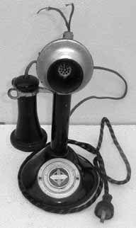
SIP promotes the ability to call a party without the need for a SIP gateway or gatekeeper, as long as you know the recipient’s sip@ address, called a SIP Uniform Resource Indicator (URI). To pay homage to the pioneering Mr. Strowger, we have included this hack to connect a rotary phone, such as a 1920 Western Electric candlestick phone (Figure 5-5), to a VoIP network.
First, let me give you a quick overview of how a rotary phone works. The rotary phone provides signaling to the central office by establishing a flow of current and then interrupting the flow momentarily to signal a pulse. The number of pulses produced in a given time period represents the number being dialed. Five pulses represent the number 5.
Adding a rotary phone to a VoIP network is a relatively painless process, as long as you can build an intermediary gateway that understands pulse signaling and SIP, and can signal both legs of the call. What can be painful is finding a VoIP device that supports rotary or “pulse” dialing. That’s why you might be better off building this gateway yourself.
Do Pulse with an IAXy
The Digium IAXy FXS gateway supports pulse dialing, providing a simple and complete solution. In fact, the IAXy is a complete gateway in and of itself: it has an analog phone port on one side and an Ethernet RJ45 port on the other, complete with a little Inter-Asterisk Exchange (IAX) user agent built in.
The Digium IAXy supports pulse dialing out of the box. Configure /etc/asterisk/iax.conf with some entries that will allow the IAXy to be used as a peer:
	[rotary]
	type=peer
	username=asterisk
	secret=supersecret
In this case, I used rotary as the IAX peer name. All you need to do, once this config is done, is register the IAXy with your Asterisk server as the IAX user asterisk. The rotary phone connects to the IAXy. Now you can use the rotary phone as you would any valid endpoint in your dial plan by routing calls to IAX/rotary using a Dial command.
Do Pulse with a Wildcard
If you opt to use Digium’s Wildcard TDM400 with an FXO module installed, you’ll need to add a line of code to the /etc/asterisk/zapata.conf file on the Asterisk phone system. In the Zaptel channel section of zapata.conf for this particular FXO channel, the following bit of config will enable the FXO port to support pulse dialing:
pulsedial=yes
Once you have modified the zapata.conf file, connect your home line to the FXO port. To test, go off-hook and try dialing an extension off the Asterisk system from the rotary phone. Remember that using a rotary phone takes a little longer to dial, so be patient. Once you have confirmed that you can dial internally, access the outside line configured for pulse dialing and call someone.
“Pass Through” Pulse Dialing Signals
With many of the other VoIP product manufacturers, the rotary end-to-end solution is not as easy to configure or operate. Most VoIP gateways support pulse dialing on the FXO connections to the phone company. But they typically do not support pulse dialing with the FXS connections (i.e., the phones). A simple hack to overcome this limitation, at least in theory, is available on some of these gateways. One could assign a dedicated FXO port that is enabled for pulse dialing directly to an FXS port. The FXS port in turn would automatically seize the outside line when the rotary phone goes off-hook. In this way, the pulse signals sent by the phone are “passed through” to the phone line.
The drawback of this configuration is that you will not be able to dial internal extensions directly. Oh, and you’ll be scratching your head if your local central office doesn’t support pulse dialing! Make sure your local central office supports pulse dialing, or this hack definitely won’t work.
Do Pulse Without Any Special Hardware
If none of the previous solutions turns your crank, there’s yet another way you can use your classic rotary-dial phone with modern telephony services like VoIP and your tone-dialing-only phone company. If you have Yahoo! Widgets (formerly Konfabulator), you can actually do tone dialing via your rotary phone with the help of your Windows PC or Mac. Download and install Harry Whitfield’s totally ‘leet DTMF Dial widget (http://www.widgetgallery.com/view.php?widget=35922).
By taking your old-school phone off the hook and holding its mouthpiece up to your computer’s speakers while dialing on the widget, the DTMF tones this widget generates will be sent through the phone line to the phone company (or to your VoIP ATA if you use a VoIP service). Just make sure the volume on your computer is up high enough for the mouthpiece to pick up the sound of the tones.
—Joel Sisko
[1] I’ve since learned that “true” bat phones not only are red, but must also reside in a glass cake cover when not in use.