
This chapter covers two Internet Engineering Task Force (IETF) gateway control protocols that control Voice over IP (VoIP) gateways from external call-control elements: Media Gateway Control Protocol (MGCP) and H.248/MEGACO. These gateway control protocols are designed to support VoIP architecture, where the media functions are separated from call-signaling functions. Therefore, their use is prevalent in large trunking gateways and residential gateways. MGCP is widely deployed and is the focus of this chapter. H.248/MEGACO is another contending protocol, and it is briefly explained at the end of this chapter. MEGACO stands for media gateway control, but do not confuse it with MGCP.
MGCP is a protocol used by media gateway controllers (MGC, also known as call agents) to control media gateways (MG). MGCP is based on a master/slave paradigm in which MGC is the master that issues commands to the MG (slave). The MG acknowledges the command, executes it, and notifies the MGC of the outcome (successful or not). In this architecture, the MG handles the media functions, such as conversion of time-division multiplexing (TDM)/ analog signals into Real-time Transport Protocol (RTP)/Real-time Transport Control Protocol (RTCP) streams. MGC handles the call-signaling functions.
In this model, the call-control intelligence resides in the MGC, and the MG is a “dumb” entity that acts on the commands of the MGC.
MGCP messages are carried over User Datagram Protocol (UDP). Because UDP does not guarantee message delivery, messages are retransmitted, if needed.
MGCP has its historic roots in two other earlier protocols: Simple Gateway Control Protocol (SGCP) and Internet Protocol Device Control (IPDC). This chapter covers MGCP version 1.0 as described in RFC 2705 and does not go into the details of SGCP, IPDC, or earlier versions of MGCP.
MGCP uses Session Description Protocol (SDP) to describe the media sessions. SDP describes session parameters of the media flow between the MGs such as IP addresses, the UDP port, RTP profiles, and multimedia conference capabilities. MGCP follows the conventions of SDP as defined in RFC 2327, and implementations are expected to conform. The SDP specification defines several media types; MGCP, however, limits the usage of SDP to two media types: audio circuits and data access circuits.
Call agents use the following SDP parameters to provision telephony gateways:
IP addresses. —Use remote gateway, local gateway, or multicast audio conference addresses to exchange RTP packets
UDP port. —Indicates the transport port used to receive RTP packets from the remote gateway
Audio media. —Specify audio media, including codec
The MGCP assumes a connection model in which the basic constructs are endpoints and connections (see Figure 13-1). Connections are grouped in calls. One or more connections can belong to one call. Connections and calls are set up at the initiative of the MGC. Before going into the details of MGCP, the sections that follow describe endpoints and connections in further detail.

Endpoints are sources or sinks of data. They are either physical or logical entities that exist in an MG.
One example of a physical endpoint is an interface on an MG that terminates a circuit originating from a public switched telephone network (PSTN) switch.
An example of a logical endpoint is an announcement server endpoint that plays/streams the announcement based on a command from the call agent.
Physical endpoints typically require hardware installation, whereas creation of logical endpoints can be performed in software.
Each endpoint is identified by an endpoint-identifier that has two components:
The domain name of the MG that contains the endpoints
A local name or identifier within that gateway
Connections can be either point-to-point or multipoint. A point–to-point connection is an association between two endpoints with the purpose of transmitting data between them. You establish a multipoint connection by connecting the endpoint to a multipoint session.
Create a connection on each endpoint that will be involved in a call. Each connection is designated locally by a connection ID and is characterized by a set of connection attributes.
The endpoints that are involved in a connection could be in separate gateways or in the same one.
A group of connections composes a call. Call agents assign call identifiers, which are unique for each call and are globally unique throughout the system. A unique call identifier links all connections that are associated with a call. This identifier enables accounting or billing mediation to occur for calls.
MGCP implements the media gateway control interface as a set of transactions. The transactions are composed of a command and a mandatory response.
All MGCP commands consist of a command line, followed by a set of parameter lines, and optionally followed by a session description. The command line has the following format:
<Command name> <Transaction-ID> <Endpoint-ID> <MGCP ver>
Each parameter line, in turn, consists of a parameter code followed by a parameter value.
All responses consist of a response header followed by an optional session description.
Although RFC 2705 has no formal classification, for ease of understanding, you can classify MGCP commands into three categories:
Basic call control commands. —These are used in almost every call interaction. They are as follows:
CreateConnection (CRCX)
ModifyConnection (MDCX)
DeleteConnection (DLCX)
Advanced call control commands. —MGC might need to know about the occurrence of certain call-related events in an endpoint. Typical examples of these events are dual-tone multifrequency (DTMF) digits, fax tones, off-hook/on-hook events, and so on. MGCP provides an interface for the MGC to request the gateway to watch for certain events on the endpoints and report their occurrence to it. The MGC uses the NotificationRequest (RQNT) command to request the gateway to report the occurrence of certain events. The gateway reports the occurrence of these events to the MGC using the Notification (NTFY) command.
Management commands. —These are not directly related to call control, but the MGC and the gateway exchange them to inform each other about certain non-call-related events. For example, a gateway might experience a hardware problem on some of its endpoints and need to inform the MGC about this. MGCP provides four different commands for management purposes:
AuditConnection (AUCX)
AuditEndpoint (AUEP)
RestartIn-Progress (RSIP)
EndpointConfiguration (EPCF)
The sections that follow describe each of the more commonly used MGCP commands and briefly explain the commonly used parameters that can appear in the particular command. Each parameter code is provided in parentheses. This is not an exhaustive listing. Refer to RFC 2705 for an exhaustive listing of the parameters (http://www.ietf.org/rfc/rfc2705.txt).
As its name indicates, this command creates a connection between two endpoints. The parameters for the CreateConnection command provide the necessary information to the gateway (GW) to build a connection:
Call ID. —This is a globally unique parameter that the MCC assigns. All connections that are related to a call share this identifier.
Notified Entity (N). —This optional parameter specifies where to send notifications.
Local Connection Options (L). —This parameter describes data communication characteristics that are used to execute the CreateConnection command. The fields in this parameter include encoding method, packetization period, bandwidth, type of service (ToS), and use of echo cancellation. By default, echo cancellation is always performed.
Mode (M). —This parameter dictates the mode of operation for the connection. The options are full duplex, receive only, send only, inactive, and loopback.
Remote Connection Descriptor (RC). —This parameter indicates the connection descriptor for the remote side of the connection, typically on the other side of the IP network. This parameter might have a null value if the information for the remote end is not yet known.
The ModifyConnection command changes the characteristics of the gateway view of a connection or call. The allowed parameters and fields in ModifyConnection are the same as those in the CreateConnection request, with the addition of the Connection ID parameter. The Connection ID parameter uniquely identifies the connection at the endpoint. You can change the following connection parameters by using the ModifyConnection command: encoding scheme, packetization period, echo cancellation, and connections to activate or deactivate.
A call agent or a gateway uses the DeleteConnection command to terminate a connection. Call agents use this request to terminate a connection between two endpoints or to clear all connections that terminate on a given endpoint. The gateway might issue this command to clear connections if it detects that an endpoint can no longer send or receive audio. If the gateway clears a connection, a reason code is included in the message indicating the cause.
After connections are terminated, gateways should place the endpoint into inactive mode, thus making it available for a subsequent session. A valuable attribute of the DeleteConnection command is that it distributes statistics regarding a call. Table 13-1 lists the statistical data contained in the DeleteConnection message.
Table 13-1. Statistical Information from the DeleteConnection Message
Data | Explanation |
|---|---|
Packets sent | Number of packets sent on the connection |
Octets sent | Number of octets sent on the connection |
Packets received | Number of packets received on the connection |
Octets received | Number of octets received on the connection |
Packets lost | Number of packets lost as indicated by sequence numbers |
Jitter | Average interpacket delay in milliseconds |
Latency | Average latency in milliseconds |
The MGC uses the NotificationRequest command to request the gateway to send notifications upon the occurrence of specified events in an endpoint. The two important parameters used in this command are the Requested Events parameter, identified by the parameter code R, and the Signal Requests parameter, identified by the parameter code S. Before this chapter goes in to the details of other parameters, it is important to understand the R and S parameters.
The Requested Events (R) parameter contains the list of events that the gateway is requested to detect and report on to the call agent. Possible events in the list include fax and modem tones, continuity tone and detection, on-hook and off-hook transition, flash hook, channel-associated signaling (CAS), wink, and DTMF (or pulse digits). In addition, a requested action can qualify each event. The actions, when specified, are encoded as a list of keywords, enclosed in parentheses, and separated by commas. Table 13-2 lists the codes for various actions.
When no action is explicitly specified, the default is to notify the event to the MGC. The following is an example of the “requested events” parameter line:
R: hu(N)
In this example, the gateway is requested to look for the hu (hang-up/on-hook event) and notify immediately (denoted by action code N) when that event occurs.
The Signal Requests(S) parameter specifies a set of signals that the gateway is asked to apply to the endpoint. The commonly used signals include ringing and distinctive ringing, ring back, dial, intercept, busy, answer, call waiting, off-hook warning, and continuity tones. Signals are split into three different types depending on their behavior:
On/Off (OO). —These signals are applied until they are turned off.
Time-Out (TO). —After these signals are applied, they remain until they are turned off or until a time-out occurs based on a signal-specific time period.
Brief (BR). —This signal duration is short and stops on its own.
Table 13-3 lists the common events and signals. For the signals, the type of event is also specified. Note that the same event can have a different duration based on the package it is part of.
Table 13-3. Events and Signals
Event Symbol | Definition | Duration |
|---|---|---|
Hd | Off-hook transition | OO |
Hu | On-hook transition | OO |
Dl | Dial tone | Handset emulation package -TO (120 s) |
Rg | Ringing | Handset emulation package -TO (30 s) |
Hf | Flash hook | BR |
Bz | Busy tone | Handset emulation package - OO |
Aw | Answer tone | OO |
Wt | Call-waiting tone | TO (30 s) |
ci(string) | Caller ID | BR |
Mt | Modem tone detected | - |
Ft | Fax tone detected | - |
Cg | Network congestion tone | TO |
It | Intercept tone | OO |
Wk | Wink | BR |
Wko | Wink off | BR |
dtmf 8 | DTMF digit 8 | BR |
mf 9 | MF digit 9 | BR |
Ann | Play an announcement | TO (var.) |
Java | Load a Java script | TO (var.) |
Other parameters that are typically present in NotificationRequest are as follows:
Notified Entity (N). —If present, this specifies where to send notification. If absent, it indicates that notification should be sent to the originator.
Request Identifier (X). —This correlates the NotificationRequest command with the notification that it triggers.
The gateway sends a Notification based on requested events in the notification request and on the occurrence of these observed events. The Notification command contains the following parameters:
Notified Entity (N). —If present, this parameter specifies where to send notification. If absent, this parameter indicates that notification should be sent to the originator.
Requested Identifier (X). —This parameter is equal to the “request identifier” in the NotificationRequest. It correlates the request to the notification.
Observed Events (O). —This parameter contains a list of events that the gateway detected based on the requested event parameter in an earlier NotificationRequest command from the MGC.
The call agent can use the AuditEndpoint command to determine the status of an endpoint. This is typically done at initialization of the call agent to find the status of all the endpoints it controls. This request contains an Endpoint ID parameter that identifies the endpoint being audited and a Requested Information parameter containing the following subparameters:
Endpoint List. —This identifies the endpoint that is being audited. You can use a wildcard to indicate all endpoints that match the wildcard.
Notified Entity (N). —This is the notified entity for active notification requests.
Requested Events (R). —This is a list of currently requested events.
Digit Map. —Endpoint currently uses this. Digit maps are described in the later section titled “Advanced MGCP Features.”
Signal Requests (S). —This is a list of signal requests that are currently applied to an endpoint.
Request Identifier (X). —This is an identifier for the last “NotificationRequest” received by an endpoint.
Connection Identifiers (I). —This is a list of the current connections that exist for the specified endpoint.
Detect Events (T). —This is a list of events that are currently being detected in quarantine mode.
Local Connection Options (L). —This is a list of all current values, such as codec and packetization period. You can use this parameter to request the current event packages that are supported on the specified endpoint.
The response from the gateways for the AUEP will include information about each of the items for which auditing information was requested.
Call agents use the AuditConnection command to retrieve information about connections. This command contains the Endpoint ID and Connection ID indicating the location and connection that are being audited. The Requested Information subparameters contain the following information:
Call ID. —This is the unique identifier of the call to which the Audited connection belongs.
Notified Entity (N). —This is the currently notified entity for the connection.
Local Connection Options (L). —These are the options that are currently being applied for this connection.
Mode (M). —This is the current mode of connection.
Remote Connection Descriptor (RC). —This is the remote SDP that is being used for the connection.
Local Connection Descriptor (LC). —This is the gateway used for the connection.
Connection Parameters (P). —This is the current value of the parameter at the Audited connection.
The gateway uses the RestartIn-Progress command to inform the call agent that an endpoint or group of endpoints was taken out of service or is back in service. The RestartIn-Progress command contains the following parameters:
Endpoint id. —This identifies the endpoint that is taken in or out of service.
Restart Method (RM). —This specifies one of the following different types of restarts:
The graceful restart method indicates that specified endpoints will be taken out of service after a specified time and that the call agent should not attempt to establish new connections.
The forced restart method indicates that endpoints were abruptly taken out of service and that connections were lost.
The restart method indicates when endpoints that have no existing connections will be put back in service.
A disconnected method indicates that the endpoint has become disconnected and is trying to establish connectivity.
Restart Delay (RD). —This is used to express delay in number of seconds.
The EndpointConfiguration command enables the call agent to specify the encoding of signals that the endpoint receives. This is particularly useful in international circumstances that use both µ-law and A-law encoding techniques. This command passes the encoding information to the gateway with the Bearer Information (B) parameter, which identifies the coding technique for the data received on the line side of the endpoint it identifies. Currently, the only subparameters that are defined are A-law and µ-law.
All MGCP commands are acknowledged. The acknowledgment carries a return code, which indicates the status of the command. The return code is an integer number for which four ranges of values have been defined:
Values between 100 and 199 indicate a provisional response.
Values between 200 and 299 indicate a successful completion.
Values between 400 and 499 indicate a transient error.
Values between 500 and 599 indicate a permanent error.
Table 13-4 lists the return codes and an explanation for each code.
Table 13-4. MGCP Return Codes
Return Code | Explanation |
|---|---|
100 | Command is currently being executed. Final response to follow. |
200 | Normal transaction execution. |
250 | Connection was deleted. |
400 | Unable to execute transaction because of transient error. |
401 | Telephone is already off-hook. |
402 | Telephone is already on-hook. |
500 | Unable to execute transaction because endpoint is unknown. |
501 | Unable to execute transaction because endpoint is unready. |
502 | Unable to execute transaction because of insufficient endpoint resources. |
510 | Unable to execute transaction because of protocol error detection. |
511 | Unable to execute transaction because of request containing unrecognized extension. |
512 | Unable to execute transaction because of gateway being unable to detect one of the requested events. |
Unable to execute transaction because of gateway being unable to generate one of the requested signals. | |
514 | Unable to execute transaction because of gateway being unable to send the specified announcement. |
515 | Transaction refers to an incorrect Connection ID. |
516 | Transaction refers to an unknown Call ID. |
517 | Unsupported mode. |
518 | Unsupported event package. |
519 | Gateway does not have a digit map. |
520 | Unable to complete transaction because of endpoint restarting. |
522 | No such event or signal. |
523 | Unknown action or combination of actions. |
524 | Inconsistent with local connection options. |
This section illustrates a few typical call flows with an explanation of the semantics of each message. The call flows are presented in order of increasing complexity. Note that the call flows presented here are shown as an example for illustration purposes. An implementation for a particular vendor of MGCP might follow a different call flow.
A simple point-to-point call is set up using two different commands: CreateConnection and ModifyConnection.
Figure 13-2 shows a call flow for a call setup between two endpoints. The endpoints are assumed to be on different gateways, and the MGC controls both the gateways. Only the relevant portions of the messages are shown in the figure. The originating side and a terminating side of this two-party call are labeled with suffixes Orig and Term, respectively. Messages in the figure are labeled numerically, and the corresponding label is referenced in the explanation that follows. Of course, the labels are not part of the MGCP messages.
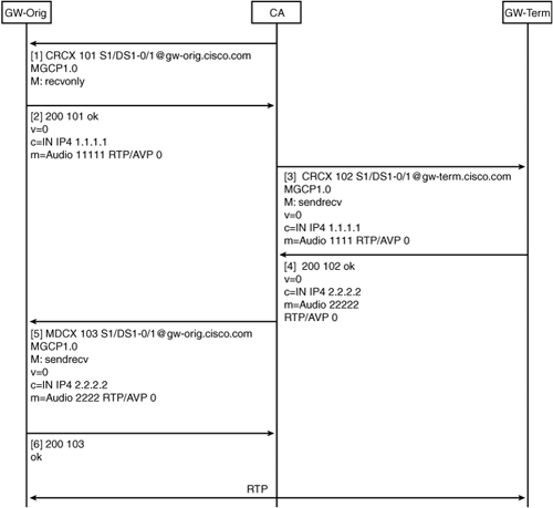
The call agent sends an initial CRCX to the GW-Orig and specifies endpoint S1/DS1-0/1. The connection mode is set to recvonly. This setting indicates to the GW-Orig that the endpoint should receive media from the IP network but not send media to the IP network. This is necessary because the call agent has not set up the connection on GW-Term and hence does not know the session description at that end.
GW-Orig responds with a 200/OK indicating that the connection was created successfully and providing a local session description (encoded per SDP specification). This session description includes the local IP and port (1.1.1.1 and 11111) that the gateway has opened to receive RTP streams. SDP also indicates that the codec being used is G.711µ-law (denoted by RTP/AVP 0).
The call agent then sends a CRCX to endpoint S1/DS1-0/1 on GW-Term. The session description received from GW-Orig is included in the RemoteConnectionDescriptor of this CRCX, and the mode is set to sendrecv.
GW-Term responds with a 200/OK and includes its own session description in the response.
The call agent passes the SDP of GW-Term to GW-Orig in a MDCX command and changes the connection mode to sendrecv.
After GW-Orig executes the MDCX command and responds with 200/OK, call setup is complete and RTP streams flow between GW-Orig and GW-Term.
The call flow discussed in the preceding section showed you that setting up connections using MGCP is fairly straightforward. However, the call flow does not tell you how and why the call agent decided to set up the connection between those two endpoints. In real life, the call agent learns about this from external signaling. A typical example is an SS7 trunk terminating on the call agent. In such a case, the SS7 messages trigger the actions of the call agent.
Figure 13-3 shows the interaction between SS7 messages and MGCP.

An initial address message (IAM) [1] comes in to the call agent on an SS7 trunk. This action triggers the call agent to analyze the IAM and decide how to handle it by consulting its local configuration. The local configuration (or an external database lookup) tells the call agent to set up a call between the two endpoints ep-orig and ep-term on the gateways GW-Orig and GW-Term.
The call agent sends two CreateConnection messages [2] and [4] that are similar to the call flow illustrated in Figure 13-2. After PSTN-term seizes the line, it sends an SS7 ACM [7] message to the call agent. Then the call agent sends an MDCX [8] to GW-Orig. Notice that the ConnectionMode is now set to recvonly. This is because, at this point, only the ringing tone needs to flow back to the originating side. The originating side cannot send audio yet.
After the terminating phone is picked up, PSTN-Term sends an ANM [11] message to the call agent. This triggers the call agent to send an MDCX to GW-Orig setting the mode to sendrecv. This completes the setup of gateways for two-way audio.
This section outlines some of the advanced features of MGCP, including the following:
The concept of events and signals is central to MGCP. A call agent can ask an MG (via a RQNT message) to be notified about certain events occurring in an endpoint (such as off-hook events), and a call agent can request certain signals (such as dial-tones) to be applied to an endpoint.
Events and signals are grouped in packages within which they share the same namespace. A particular endpoint might support one or more packages. Table 13-5 lists the ten basic packages defined in MGCP. Note that additional event names and packages can be defined by implementers and registered with Internet Assigned Numbers Authority (IANA).
RFC 2705 has specific recommendations for which event packages should be implemented on certain endpoint types. This is done to enable interoperability between multivendor gateways and call agents. Table 13-6 lists the basic endpoint types, their profiles, and their supported packages.
Table 13-6. Endpoint Types and Supported Packages
Gateway | Supported Packages |
|---|---|
Trunk gateway (ISUP) | G, D, T, R |
Trunk gateway (MF) | G, M, D, T, R |
Network Access Server (NAS) | G, M, T, N |
NAS/VoIP gateway | G, M, D, T, N, R |
Access gateway (VoIP) | G, D, M, R |
Access gateway (VoIP, NAS) | G, D, M, R |
Residential gateway | G, D, L, R |
Announcement server | A, R |
In many cases, the MGC needs to collect digit events that occur at the endpoint. Residential gateways typically use this system to collect the numbers that a user dials. Trunking gateways can use digit maps to collect access codes and other things. One approach is for the gateway to notify the MGC of dialed digits as soon as they are dialed. This digit-by-digit approach results in numerous RQNT and NTFY message exchanges between gateway and MGC.
The alternative approach to using digit maps is for the MGC to load the GW with a list of possible matches for dialed digits and to notify the MGC when a match is made. The digit map is expressed using a syntax derived from the UNIX egrep command.
You can apply only one RQNT command to a media gateway at a given time. After the event that is specified in the RQNT occurs at the endpoint, the media gateway sends a NTFY to the MGC informing it of the occurrence. Only then can the MGC send a new RQNT with a new set of Requested Events. This gives rise to the possibility of a race condition in which some of the interesting events might occur at the endpoint while the gateway has sent a NTFY for the older RQNT but has not yet received the new RQNT from the MGC.
To alleviate this problem, MGCP introduced the concept of embedded notification request. Using this construct, the MGC can embed one notification request within another. The media GW applies the embedded notification request as soon as a Requested Event occurs without waiting for further instruction from the MGC. The embedded NotificationRequest can include a new list of Requested Events, Signal Requests, and a new digit map. An embedded NotificationRequest is specified by using action code E in the Requested event list. Following is an example of an embedded NotificationRequest in a Requested Events (R) parameter line:
R: hd(E(R[0-9]))
This tells the gateway to look for the hd event. As soon as the hd event occurs, the gateway should apply [0-9] as the requested event.
MGCP is typically used when IP is the bearer network for carrying media. However, MGCP enables a connection to be established over several other types of bearer networks. This includes audio transmission over an ATM network using ATM adaptation Layer 2 (AAL2) and TDM-to-TDM connections (hairpinning) where a call originating from a PSTN network is sent back into the PSTN network.
H.248 (as it is known in the ITU world) or MEGACO (as it is known in the IETF world) is similar to MGCP in terms of architecture and purpose. This section provides a brief description of H.248 constructs without going into the details.
The main constructs in the H.248 connection model are terminations, contexts, and commands.
Termination is the source or sink of one or more media streams. A context is an association between a collection of terminations. A termination can be in only one context at any given time. A special type of context, the null context, contains all terminations that are not in another context. For instance, in an access gateway, all idle lines are represented by terminations in the null context.
You use commands to manipulate terminations and contexts. The Add command adds a termination to a context. The Subtract command removes a termination from a context and might result in the context being released if no terminations remain. The Move command moves a termination from one context to another. The Modify command changes the state of the termination.
You can see that, in MGCP, a termination resembles an endpoint and a context resembles a call. Also, the Add command is similar to the CRCX command, and the Subtract command is similar to the DLCX command.
One of the important differences is that H.248 is connection-centric, whereas MGCP is endpoint-centric.
MGCP is a vital component for a distributed architecture based on a separation of media and signaling functions. It will continue to play an important role in the transition from a legacy network, where the components are in one monolithic platform to a network whose components are distributed.
Because this is a new and evolving industry, MGCP and H.248 have to develop over time to suit industry needs.
MGCP is a fairly simple protocol at its core and will be continue to play a vital part in packet-based voice networks for many years to come.