10
Development Methodology for BSN Systems
10.1 Introduction
Designing BSN systems is a complex task and formal methods should be adopted to obtain correct, efficient, and cost‐effective solutions. The most common approach is bottom‐up: hardware components are chosen “a priori,” followed by the communication protocols, and finally, applications are programmed atop the identified underlying infrastructure. The opposite design approach is top‐down: high‐level application requirements, driving the design process, are mapped to application‐level frameworks, i.e. a set of programming abstractions and libraries; protocol stacks and hardware platforms are defined subsequently.
This chapter describes a development methodology for BSN systems, based on the SPINE framework, that follows a hybrid hardware–software codesign approach inspired to the Platform‐Based Design (PBD).
10.2 Background
PBD [1] has been originally introduced as a methodology for the design of traditional embedded systems and more recently for WSNs. This methodology defines the design as a sequence of steps that lead from the initial high‐level system description down to the actual implementation. Each step is an iterative refinement process that translates a higher level description to a lower level one that is progressively closer to the final implementation. Each refinement step is obtained by mapping all the components of the higher level description with components (or composition of components) from a lower level description. The mapping results from solving a constrained optimization problem: the choice is a mapping that satisfies the higher level description constraints while optimizing according to a cost function defined by the designer. For each layer of abstraction, these components, along with a description of their interfaces and performance, are stored in a library, called platform. The higher the initial level of abstraction, the easier is formulating functionalities and constraints, but the more difficult is to reach to a high‐quality translation due to the semantic gap between specification and implementation.
Each refinement step is performed with a hybrid approach, where application constraints are refined in a top‐down fashion, architecture performance are abstracted in a bottom‐up fashion, and a meet‐in‐the‐middle phase decides the actual implementation as discussed above.
The formalization of the PBD methodology is based on the Agent Algebra [2], which represents a formal tool to describe the refinement process. The refinement is the expression of a function in terms of the elements of a platform.
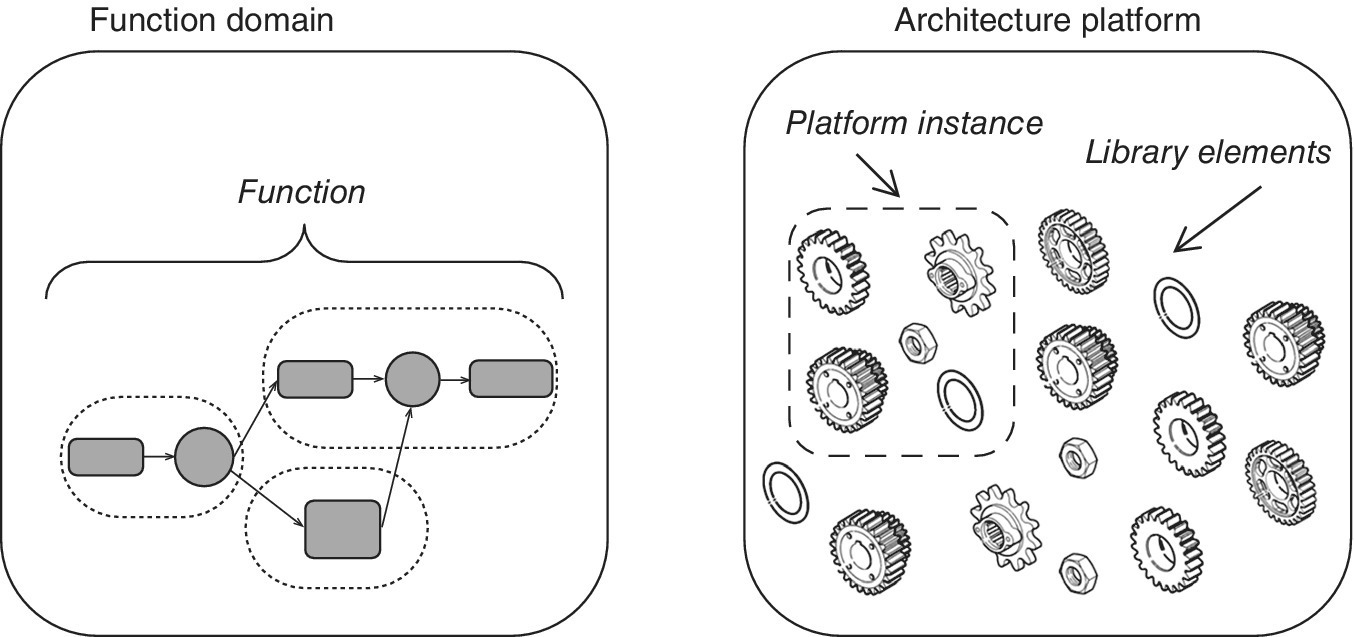
Three domains of agents are used to describe the mapping process and performance evaluation: the first two represent, respectively, the platform and the function; the third, referred to as common semantic domain (CSD), is an intermediate domain to map functions onto platform instances. A platform, depicted on the right in Figure 10.1, corresponds to the implementation search space. The function, on the left in Figure 10.1, corresponds to the specification domain. The function and the platform meet in the CSD. This domain plays the role of a common refinement and is used to combine the properties of both the platform and the specification domain that are relevant to the mapping process. The function is mapped onto the CSD as depicted in Figure 10.2. A platform instance is projected onto the CSD by considering the agents that can be implemented with that particular instance. This projection, represented by the arrows that originate from the platform in Figure 10.2, may or may not have a greatest element. If it does, the greatest element represents the nondeterministic choice of the functions that are implementable by the instance.

Figure 10.1 Architecture and function platforms.

Figure 10.2 Mapping of function and architecture.
The CSD is partitioned into different areas: the useful one contains the Admissible Refinements and is determined by the intersection between the refinements of the function and the functions that are implementable by the platform instance. Each of the admissible refinements encodes a particular mapping of the components of the function onto the services offered by the selected platform instance. The vertex of this area corresponds to the Best Admissible Refinement and the implementation choice should ideally bring to that point. After an implementation is selected at a certain level, the same refinement process is iterated so to obtain a lower level of abstraction that is hence closer to the final implementation. The PBD shows its recursive nature, as the process is repeated at increasingly more detailed levels of abstraction, terminating once the final implementation is obtained.
10.3 Motivations and Challenges
Today the choice of an architecture platform for developing BSN systems is more an art than a science. In the application perspective, the requirements that lead this choice are typically wearability, size, cost, and performance. For a particular application, we require that, for instance, the platform should be able to handle (and preprocess) a minimum sensor sampling rate, which has both computational power and memory performance involvements. Since each application requires different sets of functions, the constraints identify different (embedded) platforms, where more advanced applications yield to harder architectural constraints.
In the IC manufacturers’ perspective, production and design costs also imply adding platform constraints. The intersection of the two sets of constraints defines the architecture platforms that can be used for the final product. It is worth noting that the result can be an overdesigned platform instance for a given application; in other words, the full potential of the platform is partially unexploited. Overdesign, to some degree, is not necessarily an issue, as it can reduce design costs and time‐to‐market of new products.
So, the “design” of a BSN system should be supported by a formal methodology that is able to allow the designer exploring the possible choices looking for the most effective and efficient trade‐off solution.
10.4 SPINE‐Based Design Methodology
Through the experience gained by using SPINE for the development of several BSN applications (see Chapter 11), we identified a novel method to support rigorous BSN system design that helps the designer to obtain reliability, efficiency, and true interoperability among different systems as well as different hw/sw implementation of the same system. The SPINE‐based Design Methodology (SPINE‐based DM) is inspired by the well‐known PBD [1]. Here, however, the necessary platforms are opportunely semi‐instantiated.
Specifically, according to the PBD, and in particular following the indication of Ref. [3], three layers of abstraction and corresponding platforms have been defined: the Service Platform at the application layer, the Protocol Platform to formalize communication protocols, and the Implementation Platform to describe hardware devices. Each design integrates an instance of these layers. Specifically, at each given refinement step, the design consists of a complete instance of the BSN system under development. We identified three main refinement steps: high level, detailed design, and implementation.
However, our approach differentiates from the standard PBD methodology because, with the intent of guiding the designer during the development of a SPINE‐based efficient BSN system, some of the platforms we identified are semi‐instantiated. Specifically:
- The Service Platform is bound to the high‐level API provided by the SPINE Framework (see Chapter 3). Application requirements and functionalities can be mapped freely to the flexible SPINE API and services.
- The Implementation Platform includes many hardware. The designer has the opportunity to choose the most suitable one according to low‐level system requirements. The Implementation platform is semi‐instantiated too, as we assume, at the sensor‐node level, the use of TinyOS‐based architectures onto which the node‐side of the SPINE Framework has been deployed, and, at the coordinator level, the use of Java‐ and Android‐powered personal devices/computers that will be used as SPINE‐based BSN coordinators.
- The Protocol Platform allows choosing two protocol stacks: Bluetooth and IEEE 802.15.4. This platform is the last to be instantiated as the choice often depends on the mapping made at the Implementation Platform (particularly on the radio standard available on the target devices).
10.4.1 A Pattern‐Driven Application‐Level Design
The application‐level design of a SPINE‐based BSN application can be guided by pattern‐driven strategies. In the following, we describe two of such useful design patterns, both completely supported by SPINE:
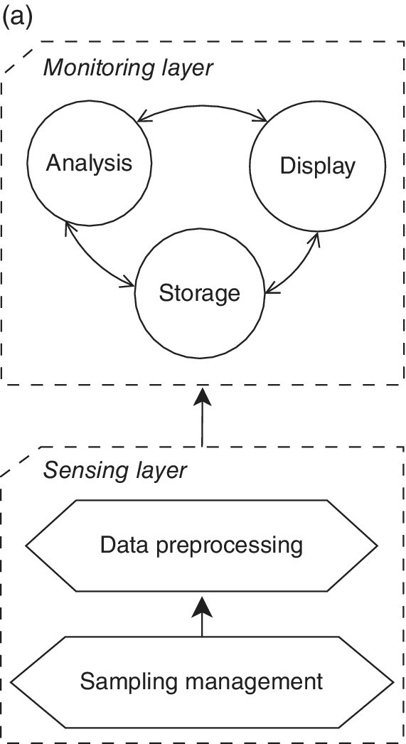
- Sensor Data Collection for Monitoring: The simplest pattern supports the development of BSN systems for data collection from a set of wearable sensors into the coordinator which, in turn, visualize, store, and/or analyze such collected data. The pattern architectural schema is depicted in Figure 10.3a. Its main components are organized in two layers:
- Sensing, in which data are collected from the sensor nodes.
- Monitoring, in which data can be visualized, analyzed, and stored.
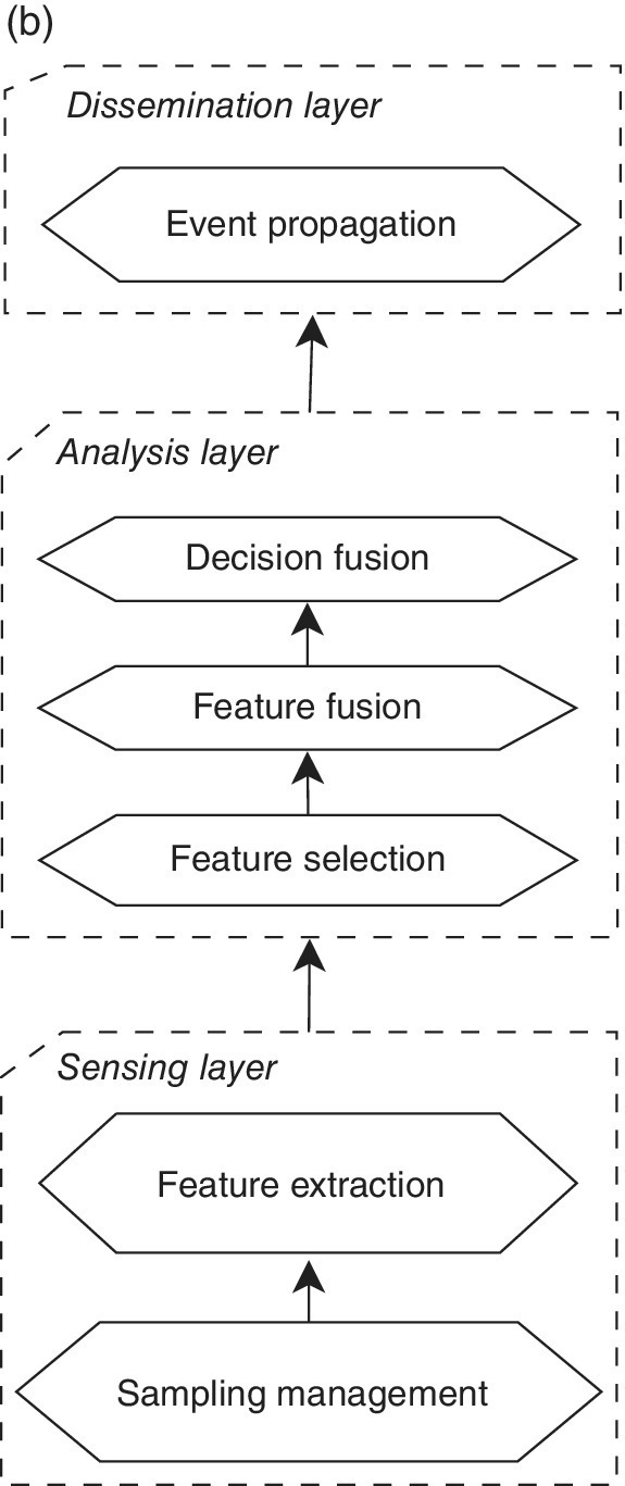
- Multisensor Data Fusion for Detection/Classification of Events: This pattern extends the previous by introducing the detection and/or classification of events of interest, such as accidental falls, physical activities, posture or gestures, mental states, and so on (see Chapter 11). Its architectural schema is depicted in Figure 10.3b. The main components are organized in three layers:
- Sensing, defined as for the previous pattern.
- Analysis, in which decisions are inferred from available sensory data.
- Dissemination, in which extracted information is provided to end‐user BSN applications.


Figure 10.3 Pattern architectural schemas: (a) Sensor Data Collection for Monitoring; (b) Multisensor Data Fusion for Detection/Classification of Events.
10.4.2 System Parameters
According to the proposed method terminology, the main parameters affecting BSN‐based applications can be classified as follows:
- Application‐level parameters: system accuracy, reliability, and responsiveness. Accuracy is application‐specific and related to pattern recognition and event classification such as activity recognition or stress detection accuracy (see also Sections 11.2and 11.3). Reliability is very relevant for life‐critical applications (e.g. early detection of cardiac attacks, epilepsy attacks, and fall detection). A fuzzy definition of responsiveness is the ability of a system to provide the necessary feedback to the user within acceptable times; it is application‐specific too, as it depends on the processing load required to perform the main operations, e.g. computation of flexion/rotation degrees in motor rehabilitation digital assistants (see also Section 11.5), or detection of a handshake in a handshake detection system (see also Section 11.4).
- Protocol‐level parameters: bandwidth and delay that depend on sensor sampling frequency, sensor‐ and application‐specific generated data, and on communication protocols themselves. It is worth noting, however, that specific network synchronization requirements can be handled by the selected protocol (e.g. by using a TDMA technique), whereas more complex synchronization constraints must be handled at the Application level.
- Device‐level parameters: energy consumption, memory, and processing capabilities requirements. The energy consumption depends on duty cycle, sensor type and sampling frequency, radio usage, and application‐specific signal processing. Memory (system and mass memory) requirements depend on (i) software platform tailoring (i.e. specific to our design method, for which TinyOS and SPINE components are needed), (ii) sampling frequency, (iii) buffering allocation parameters for sensor data storing and computation (e.g. buffer pool size, window, and shift size), and (iv) on application‐specific signal filtering and data processing. Computing power is mostly determined by application‐specific signal processing.
10.4.3 Process Schema
The SPINE‐based Platform Design [4] process schema is depicted in Figure 10.4. The process is iterative and is composed of the following steps (carried out by Modeler, Designer, and Developer roles):
- Requirements Analysis (RA): it produces a set of functional and nonfunctional requirements driving the design flow.
- High‐Level Design (HLD): it produces a high‐level design of the BSN system on the basis of the identified requirements. In our methodology, a HLD is an instance of the SPINE framework integrated with selected protocols, sensors, and platforms.
- Performance Estimation of HLD: it produces estimation measurements of the HLD performance by using available analytical/simulation methods. Although the results cannot be detailed at this refinement level, they can still provide insights on the feasibility (or convenience) to translate the available HLD into a DD. If the requirements are not satisfied, the process must step back to the HLD step.
- Detailed Design (DD): it produces the detailed design of the available HLD instance. The HLD is refined at each of the three layers of SPINE‐based DM by following the pattern‐driven design described previously.
- Performance Estimation of DD: it provides analysis of the DD by testing or estimating the DD performance through analytical and/or simulation methods and also by mapping selected DD components onto the device level for testing. The obtained results are more accurate than the Performance Estimation HLD output; they provide fine‐grained indications on the feasibility of obtaining an effective and efficient implementation of the DD instance. If the requirements are not satisfied, the process must go back to the DD or even the HLD step.
- Implementation: it produces an implementation of the DD output; the BSN system can be finally deployed, executed, and tested.
- Deployment: it defines deployment details of the BSN system.
- System Performance Evaluation: it provides detailed test cases of the BSN system and detailed performance measurements are extracted for its validation. The result of this analysis provides a full‐fledged test of the whole system. If the requirements are not satisfied, the process must go back to the DD or even the HLD step.

Figure 10.4 SPINE‐based Platform Design process schema.
10.5 Summary
This chapter has introduced a specialization of the PBD methodology for system‐level design of BSN applications. First, the PBD approach has been briefly described. Then, a PBD methodology, previously proposed for the design of WSN systems, has been specialized for the more specific BSN domain. Finally, the methodology has been concretely shown in relation to the SPINE framework.
References
- 1 Keutzer, K., Newton, A.‐R., Rabaey, J.‐M., and Sangiovanni‐Vincentelli, A. (2000). System‐level design: orthogonalization of concerns and platform‐based design. IEEE Transactions on Computer‐Aided Design of Integrated Circuits and Systems 9 (12): 1523–1543.
- 2 Passerone, R. (2004). Semantic foundations for heterogeneous systems. PhD thesis. University of California.
- 3 Bonivento, A. (2007). Platform based design for wireless sensor networks. PhD thesis. University of California.
- 4 Fortino, G., Giannantonio, R., Gravina, R. et al. (2013). Enabling effective programming and flexible management of efficient body sensor network applications. IEEE Transactions on Human‐Machine Systems 43 (1): 115–133. doi: 10.1109/TSMCC.2012.2215852.
