1
Body Sensor Networks
1.1 Introduction
This chapter provides an overview of the state‐of‐the‐art and technology in the field of wireless body sensor networks (BSNs). After introducing the motivations and the potential applications of this emerging technology, the chapter focuses on the analysis of the architecture of sensor nodes, communication techniques, and energy issues. We will then present and compare some of the programmable sensing platforms that are most commonly used in the context of wireless sensor networks (WSNs), and in particular those applied to remote monitoring of patients. The chapter also contains an analysis of relevant vital human signals and physical sensors used for their recording. Finally, the chapter presents the hardware/software characteristics that must be taken into consideration during the design stages of a healthcare monitoring system based on BSNs. For instance, important characteristics are sensor wearability, biocompatibility, energy consumption, security, and privacy of the acquired biophysical information.
1.2 Background
The widespread use of mobile applications for patient monitoring over the last few years is radically changing the approach to the health care. In today’s society, this is gaining an increasingly important role in the prevention of diseases; the convenience, for instance in terms of health‐care costs, is significant. The BSN technology makes often use of mobile applications that allow for the transmission to a coordinator node, such as a smartphone or a tablet, information about vital signs and physical activities (movements and gestures) [1, 2]. The miniaturization and the production cost reduction are leading to the realization of extremely small‐sized sensing and computing devices with high processing capacity thus giving a great impulse to the development of WSNs, and, as a direct consequence, of BSNs. Very heterogeneous information and diversified physiological signals can be transmitted, possibly after the application of sensor fusion techniques [3], by the sensor nodes to the coordinator device.
Figure 1.1 shows a number of wearable sensing devices and their typical location on the body:
- Electrocardiography (ECG): the ECG is used to record the electrical activity (including the heart rate) of the heart over a period of time using electrodes placed on the skin.
- Blood pressure meter: also known as sphygmomanometer, it is a device used to measure (typically, both diastolic and systolic) blood pressure.
- Pulse oximetry: the oximeter is a medical device that allows us to measure noninvasively the amount of hemoglobin in the blood. Since hemoglobin binds with oxygen, it is therefore possible to obtain an estimate of the amount of oxygen present in the blood.
- Electromyography (EMG): the EMG sensor is used to monitor muscle activity, using a needle electrode inserted into the muscle for high accuracy, or, more practical and noninvasive, with simple skin electrodes. It records the activity of the muscle fibers under different conditions: at rest, during voluntary contraction up to the maximum effort, and during a sustained average contraction.
- Electroencephalography (EEG): the EEG sensor uses electrodes placed on the scalp to monitor the brain activity and capture different types of brain waves.
- Motion inertial sensors (e.g. accelerometers and gyroscopes) monitor human movements and even gestures.

Figure 1.1 Common wearable sensors and their location on the human body.
BSN systems are commonly characterized by a number of hardware and software requirements:
- Interoperability: it is necessary to ensure the continuous data transfer through different standards (e.g. Bluetooth and ZigBee) to promote the exchange of information and ensure interaction between devices. In addition, it should provide an adequate level of scalability in relation to the number of sensor nodes and the workload of the BSN.
- System device: the sensors must be of low complexity, small size, lightweight, energy efficient, easy to use, and reconfigurable. In addition, patient biosignal storage, retrieval, visualization, and analysis must be facilitated.
- Security at the device and system level: particular attention must be paid to secure transmission and authenticated access to such sensible data.
- Privacy: the BSN could be considered as a “threat” to the freedom of the individual, if the purpose of the applications goes “beyond” the medical purposes. Social acceptance to these systems is the key to their wider dissemination.
- Reliability: the whole system must be reliable at hardware, network, and software levels. Reliability affects directly the quality of monitoring because, in the worst case, the failure to observe and/or successfully notify a “critical risk event” can be lethal for the patient. Because of the limitations and requirements on communication and power consumption, the reliability techniques used in traditional networks are not easily applicable in the BSN domain and, both at the design and implementation phase, this must be taken seriously.
- Validation and accuracy of sensory data: sensing devices are subject to hardware constraints that can affect the quality of the acquired data; both wired and wireless connections are not always reliable; environmental interference and limited energy availability also affect this aspect. This can cause inconsistencies in the transmitted data and might lead to critical errors in their interpretation. It is very important that all data transmitted from the sensor nodes to the coordinator are adequately “validated” either in hardware or software, trying to identify the “critical points” of the system.
- Data consistency: for large‐scale BSNs, with many and heterogeneous sensors, a single biophysical phenomenon may be “fragmented” and only partially detectable into individual signals. This aspect arises problems of information consistency, which must be addressed through appropriate synchronization strategies, data fusion techniques [3], and/or mutual exclusion in the access to data.
- Interference: wireless links used in the BSN should try to minimize the interference issues and favor the coexistence of sensor nodes with other network devices available within the radio range.
- Biological compatibility: the wearable sensors and skin electrodes must be biocompatible and stable, as they might operate on the user for a long period of time without interruptions.
In addition to the hardware and software features, we highlight some aspects that could encourage the wide diffusion and exploitation of BSN systems:
- Costs: users expect low costs for health monitoring, yet preserving high performance of the devices used.
- Different levels of monitoring: users may require different levels of monitoring, for example, to control the risk of ischemic heart disease or of falling during movements. Depending on the operating mode, the energy level required for the power supply of the devices can also vary.
- Noninvasive easy‐to‐use devices: the devices must be wearable, lightweight, and noninvasive. They should not hinder users in their daily activities; their operation must be “transparent” to users who should ignore the details of the monitoring task.
- Consistent performance: sensors must be calibrated and accurate, and they should provide consistent measurements even if the BSN is stopped and restarted several times. Wireless links should be as robust as possible and be able to operate correctly in different (noisy) working environments.
1.3 Typical m‐Health System Architecture
Figure 1.2 shows the typical architecture of an m‐Health system based on BSN technology. It usually consists of three different tiers communicating through wireless (or sometimes wired) channels [4].
Figure 1.2 A three‐tier hierarchical BSN architecture: (1) body sensor tier, (2) personal area network tier, and (3) global network tier.
Tier 1 represents the Body Sensor Tier and includes a set of wireless wearable medical sensor nodes composing the BSN. Each node is able to detect, sample, and process one or more physiological signals. For example, a motion sensor for discriminating postures, gestures, and activities; an electrocardiogram (ECG) sensor can be used for monitoring cardiac activity; and an electroencephalogram (EEG) sensor for monitoring cerebral electrical activity, and so on.
Tier 2 is the Personal Area Network Tier and contains the personal coordinator device (often a smartphone or a tablet, but possibly a PC) running an end‐user application. This tier is responsible for a number of functions providing a transparent interface to the BSN, to the user, and to the upper tier. The interface to the BSN provides functionalities to configure and manage the network, such as sensor discovery and activation, sensory data recording and processing, and establishment of a secure communication with both Tier 1 and Tier 3. When the BSN has been configured, the end‐user monitoring application starts providing feedback through a user‐friendly graphical and/or audio interface. Finally, if there is an active channel of communication with the upper tier, it can report raw and processed data for off‐line analysis and long‐term storage. Conversely, if Internet connectivity is temporary unavailable, the coordinator device should be able to store the data locally and perform the data transfer as soon as the connectivity is restored.
Tier 3 is the Global Network Tier and comprises one or more remote medical servers or a Cloud computing platform. Tier 3 usually provides services to medical personnel for off‐line analysis of a patient’s health status, real‐time notification of life‐critical events and abnormal conditions, and scientific and medical visualization of collected data. In addition, this tier can provide a web interface for the patient itself and/or relatives too.
1.4 Hardware Architecture of a Sensor Node
A typical sensor node architecture is shown in Figure 1.3 and consists of the following main components:
- Sensing unit, each node usually includes one or multiple built‐in sensors and an expansion bus through which it is possible to attach further sensors that might be necessary for specific applications. A sensor is generally composed of a transducer and an analog‐to‐digital converter (see next bullet point). The transducers are realized by exploiting the characteristics of some materials that vary their “electrical properties” to varying environmental conditions. Many transducers used on wireless sensor nodes are based on MEMS (Micro‐ElectroMechanical Systems) technology. MEMS sensors are more efficient and require less power consumption with respect to piezoelectric sensors; furthermore, MEMS sensors are characterized by low production costs, although this could lead to less precision if compared with piezoelectric sensors.
- Analog‐to‐Digital Converter (ADC) converts the voltage value of a transducer into a digital value, which will then be used for post‐processing.
- Processing unit, the Micro‐Controller Unit (MCU) of a sensor node is usually associated with a built‐in limited memory unit to improve the processing speed and enable local online sensory data processing. The sensor node is, therefore, able to perform signal processing such as “background noise” filtering, data fusion and aggregation, and feature extraction (e.g. mean, variance, maximum/minimum value, entropy, and signal amplitude/energy). The MCU is also responsible for the management of the other hardware resources.
- Transceiver unit is the component that connects the node to the network. It can be an optical or a radio frequency (RF) device. It is also possible, and actually very useful, to use the radio with a low duty‐cycle, to help reducing the power consumption.
- External memory is needed to store the binary code of the program running on the sensor node. Some sensor platforms also include a further memory (usually a microSD flash memory) as a mass storage unit for sensory data recording.
- Power supply is the scarcest resource of a sensor node and must be preserved as much as possible to prolong its lifetime; it could be notably supported by a unit for energy harvesting (e.g. from solar light, heat, or vibration).
Figure 1.3 Typical hardware architecture of a sensor node.
1.5 Communication Medium
In a multi‐hop sensor network the nodes can interact with each other via a wireless communication medium. One choice is to use the ISM (industrial, scientific, and medical) radio spectrum [5], i.e. a predefined set of frequency bands that can be used freely in many countries. Most of the sensors currently on the market do in fact make use of a RF circuit. Another option is given by infrared (IR) communication. On the one hand, the IR communication does not require permits or licenses, it is protected from interference, and IR transceivers are very cheap and easy to realize. On the other hand, however, IR requires line‐of‐sight between the transmitter and the receiver, which makes it hardly usable for WSNs and BSNs as nodes very often cannot be deployed in such a way.
1.6 Power Consumption Considerations
A sensor node is normally equipped with a very limited energy source. The lifecycle of a sensor node heavily depends on the battery dimensions and on the processing and communication duty‐cycling. For these reasons, many research efforts are focusing on the design of power‐aware communication protocols and algorithms, with the aim of optimizing energy consumption. While in traditional mobile networks and ad‐hoc networks energy consumption is not the most important constraint, in the WSN domain it is a crucial aspect. This is true even in the specific subdomain of the BSNs. Although it is generally easier to recharge or replace the batteries of the wearable nodes, due to wearability reasons, the battery dimension (and hence its capacity) is generally much smaller than in other WSN scenarios.
In a sensor node, the energy consumption is mainly due to three tasks:
- Communication: it is the most affecting factor. Low‐power radios, strict radio duty‐cycling, power‐aware WSN‐specific communication protocols and standards, and on‐node data fusion and aggregation techniques are critical design choices for reducing the activation of the transceiver module as much as possible. It is worth noting that both transmission and listening/reception time must be optimized.
- Sensing: the power required to carry out the sampling depends on the nature of the application and, as a consequence, on the type of the physical transducers involved.
- Data processing: it must be taken into account, even though the energy consumed for processing a given amount of data is very small compared to the energy requirements for transmitting the same amount of data. Experimental studies showed that the energy cost for transmitting 1 kB of data is about the same that would be obtained by performing 3–100 million instructions on the sensor node microcontroller [6].
1.7 Communication Standards
The aforementioned requirements impose very tight restrictions on the type of network protocols that can be used in WSNs. The short‐range wireless technologies are a prerequisite, given the limited power budget available for each node. The implementation of a wireless network communication protocol that must be robust, fault tolerant, and capable of self‐configuration even in hostile environments represents a considerable technological challenge, which required (and still requires) the efforts of several standardization bodies, such as IEEE and IETF.
The IEEE 802.15.4 [7] is to date the most widely adopted standard in the WSN domain. Indeed, it is intended to offer the fundamental lower network layers (physical and MAC) of Wireless Personal Area Networks (WPANs) focusing on low‐cost, low‐speed ubiquitous communication between devices. The emphasis is on very low‐cost communication of nearby devices with little to no underlying infrastructure. The basic protocol conceives a 10 m communication range with a transfer rate of 250 kbit/s. Tradeoffs are possible to favor more radically embedded devices with even lower power requirements, through the definition of several physical layers. Lower transfer rates of 20 and 40 kbit/s were initially defined, with the 100 kbit/s rate being added later. Even lower rates can be considered with the resulting effect on power consumption. The main identifying feature of 802.15.4 is the importance of achieving extremely low manufacturing and operation costs, and technological simplicity, without sacrificing flexibility or generality. Important features include real‐time suitability by reservation of guaranteed time slots, collision avoidance through CSMA/CA, and integrated support for secure communications. It operates on one of three possible unlicensed frequency bands:
- 868.0–868.6 MHz: Europe, allows 1 communication channel.
- 902–928 MHz: North America, up to 30 channels.
- 2400–2483.5 MHz: Worldwide use, up to 16 channels.
To complete the IEEE 802.15.4 standard, the ZigBee [8] protocol has been realized. ZigBee is a low‐cost, low‐power, wireless mesh network standard built upon the physical layer and medium access control defined in the 802.15.4. It is intended to be simpler and less expensive than, for instance, Bluetooth. ZigBee chip vendors typically sell integrated radios and microcontrollers with 60 to 256 kB flash memory. The ZigBee network layer natively supports both star and tree networks, and generic mesh networks. Every network must have one coordinator device. In particular, within star networks, the coordinator must be the central node. Specifically, the ZigBee specification completes the 802.15.4 standard by adding four main components:
- Network layer, which enables the correct use of the MAC sublayer and provides a suitable interface for the application layer.
- Application layer is the highest‐level layer defined by ZigBee and represents the interface to the end users.
- ZigBee device object (ZDO) is the protocol responsible for overall device management, security keys, and policies. It is responsible for defining the role of a device (i.e. coordinator or end device).
- Manufacturer‐defined application objects, which allow for customization and favor total integration.
Bluetooth [9] is a proprietary open wireless technology standard for exchanging data over short distances (using short wavelength radio transmissions in the ISM band from 2400 to 2480 MHz) from fixed and mobile devices, creating WPANs with high levels of security. Bluetooth uses a radio technology called frequency‐hopping spread spectrum, splitting the data being sent into portions and transmitting the portions on up to 79 bands (1 MHz each). Bluetooth is a packet‐based protocol with a master–slave structure. One master may communicate with up to seven slaves in a so‐called piconet; all devices share the master’s clock. Packet exchange is based on the basic clock, defined by the master. The specification also provides for the connection of two or more piconets to form a scatternet, in which certain devices simultaneously play the master role in one piconet and the slave role in another. Although being designed for WPANs, the first versions of Bluetooth are actually suitable only for BSN systems that do not require long battery life before recharging. This is because the Bluetooth power consumption profile is significantly higher compared with 802.15.4. Other factors limiting the use of Bluetooth in the BSN domain are the high communication latency (typically around 100 ms) and the long setup time (that, due to the discovery procedure, can take several seconds).
To overcome these limitations, Bluetooth released the 4.0 version that has been called Bluetooth Low Energy (BLE) [10]. One of the BLE design driving factors is the specific support for applications such as health care, sport, and fitness. The promoter for such applications is the Bluetooth Special Interest Group in cooperation with the Continua Health Alliance. BLE operates in the same spectrum range (2400–2480 MHz) as classic Bluetooth but uses a different set of channels. Instead of 79 1‐MHz wide channels, BLE uses 40 2‐MHz wide channels. BLE is designed with two implementation alternatives: Single mode and dual mode. Small devices like watches and sport sensors based on a single‐mode BLE implementation will take advantage of the low power consumption and low production costs. However, pure BLE is not backward compatible with the classic Bluetooth protocol. In dual‐mode implementations, instead, the new low‐energy functionality is integrated into classic Bluetooth circuitry. The architecture will share classic Bluetooth technology radio and antenna, enhancing current chips with the new low‐energy stack.
ANT [11] is an ultra‐low‐power wireless communications protocol stack operating in the 2.4 GHz band. A typical ANT protocol transceiver comes preloaded with the protocol software and must be controlled by an application processor. It is characterized by a low computational overhead and high efficiency, resulting in low power consumption by the radios supporting the protocol. Similar to BLE, ANT has been targeted for sport, wellness, and home health monitoring, among other WSN application scenarios. To date, indeed, ANT has been adopted in a number of commercial wrist‐mounted instrumentation, heart rate monitoring, speed and distance monitoring, bike computers, and health and wellness monitoring devices.
The IEEE 802.15 WPAN Task Group 6 (BAN) [12] is developing a communication standard specifically optimized for low‐power devices operating on, in, or around the human body to serve a variety of applications including medical, consumer electronics, personal entertainment, and others. Compared to IEEE 802.15.4, IEEE 802.15.6 focuses specifically on BSNs, addressing their identifying characteristics such as shorter communication range (the standard supports a range of 2–5 m) and larger data rate (up to 10 Mbps), which help in decreasing power consumption and meeting safety and biofriendly requirements.
1.8 Network Topologies
The most common network topologies adopted in the BSN domain are the following:
- peer‐to‐peer
- star
- mesh
- clustered
The peer‐to‐peer (P2P) topology (see Figure 1.4) reflects BSN systems that do not rely on a coordinator station to operate. It is worth noting that a pure P2P topology is never used in practice today. Even for systems where the sensor nodes adopt a decentralized communication paradigm to reach a certain common goal, there is at least one node that interfaces with the user to receive commands and provide some sort of feedback for the events generated by the BSN.
Figure 1.4 Peer‐to‐peer topology.
The most common network topology for a BSN system is actually the star (see Figure 1.5). Here, the coordinator device acts as the center of the star and it is in charge of configuring the remote sensor nodes (which do not communicate among each other directly), and gathering the sensory information.

Figure 1.5 Star topology.
The P2P and star topologies are used for personal BSN applications (e.g. health monitoring, wellness, or sport) that do not need to interact with other BSNs.
The mesh topology (see Figure 1.6) is an extension of the star, where multiple BSNs may interact, and even collaborate, through the existence of an underlying infrastructure consisting of gateway nodes necessary to enable the communication among BSNs.

Figure 1.6 Mesh topology.
Somewhat similar to the mesh is the clustered topology (see Figure 1.7). Here, however, different BSNs may communicate without necessarily relying on a fixed infrastructure. In other words, the BSNs are able to communicate directly, typically in a P2P fashion.

Figure 1.7 Clustered topology.
Mesh and clustered topologies are adopted in complex systems, which involve different BSNs to communicate among each other. Depending on the specific application, they are often referred to as Collaborative BSNs [13] (see Chapter 7).
1.9 Commercial Sensor Node Platforms
A comprehensive analysis on commercial sensor platforms for BSN applications is out of the scope of this section. However, to provide a overview on their current status, a brief list is summarized in Table 1.1. An interesting survey on sensor network platforms can be found in Ref. [14].
Table 1.1 List of commercial sensor node platforms.
| Sensor platform | MCU | Transceiver | Code/data memory | External memory | Programming language |
| BTNode | ATmega 128L 8 MHz | 802.15.4 (CC1000), Bluetooth | 180/64 kB | 128 kB | C, nesC/TinyOS |
| Epic mote | TI MSP430 8 MHz | 802.15.4 (CC2420) | 48/10 kB | 2 MB Flash | nesC/TinyOS |
| MicaZ | ATMega 128 16 MHz | 802.15.4 (CC2420) | 128/4 kB | 512 kB | nesC/TinyOS |
| Shimmer3 | TI MSP430 24 MHz | Bluetooth | 256/16 kB | 2 GB microSD | C, nesC/TinyOS |
| SunSPOT | ARM920T 180 MHz | 802.15.4 (CC2420) | 512 kB | 4 MB Flash | JavaME |
| TelosB | TI MSP430 8 MHz | 802.15.4 (CC2420) | 48/10 kB | 1 MB Flash | C, nesC/TinyOS |
| Waspmote | ATMega 1281 8 MHz | ZigBee or Bluetooth or Wifi | 128/8 kB | 2 GB microSD | C |
| Intel Mote | XScale PXA270 13–416 MHz | 802.15.4 (CC2420), Bluetooth, 802.11b | 32 MB/32 MB | — | C, TinyOS |
In the following, we just briefly describe the main technical specifications of some of the most popular sensor node architectures.
The Intel Mote [15] is among the first wireless sensor node platforms; built on a motherboard of 3 × 3 cm and equipped with an Intel XScale PXA270 processor with 32 MB of flash memory and 32 MB of SDRAM, it allows for high‐performance computing. It integrates an 802.15.4 radio, while additional wireless standards, such as Bluetooth and 802.11b, are supported by means of attachable boards.
The Mica Mote [16] (see Figure 1.8), developed at the University of California at Berkeley, is used for research and development of networks with low‐power consumption requirements. It is equipped with an Atmel ATMEGA128 microcontroller at 4–16 MHz (on the MicaZ) with 128 kB of Flash and 4 kB of SRAM. The radio module is based on an RF transmitter at 916.5 MHz on the Mica, while on the CC2420 at 2.4 GHz on the MicaZ. The platform is distinguished by the high number of additional plug‐in sensor boards.
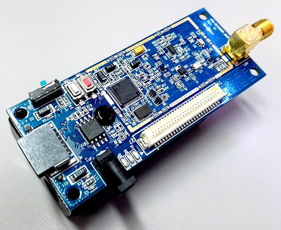
Figure 1.8 Mica Mote.
The TelosB (also known as Tmote Sky) [17] (see Figure 1.9) is an open‐source low‐power wireless sensor node platform designed by the University of California, Berkeley, for pervasive monitoring applications and for rapid prototyping of WSN systems. It integrates an 8 MHz Texas Instruments MSP430 microcontroller, humidity, temperature and light sensors, and an IEEE 802.15.4 compliant Chipcon CC2420 radio module.

Figure 1.9 TelosB Tmote Sky.
The Shimmer nodes [18] (see Figure 1.10) are specifically designed to support wearable medical applications and provide a highly extensible platform, by means of plug‐in sensor boards, for real‐time detection of movements and changes in physiological parameters. They are among the smaller nodes on the market and have a plastic cover that protects the internal electronics and the battery. Furthermore, the size and the wide availability of elastic straps (e.g. for arms, chest, wrist, waist, and ankle) makes this platform probably the most appropriate for developing BSN‐based m‐Health systems. Currently, there are four commercial revisions of the platform: Shimmer, Shimmer2, Shimmer2R, and Shimmer3. All of them have the same MCU (TI MSP430) and the same radio chipset (CC2420), support local storage media microSD, are powered by a rechargeable lithium battery, and support Bluetooth communication, thanks to a second dedicated radio module. The Shimmer3 revision is slightly different as it uses a more powerful 24 MHz MSP430 microcontroller and includes natively only the Bluetooth radio, while offering an expansion interface for connecting an additional radio or a coprocessor. The Bluetooth support is an important aspect of this platform as it strengthens the motivation for its use in market‐ready m‐Health systems, since current smartphones and tablets do have Bluetooth connectivity, but do not support the IEEE 802.15.4 standard.
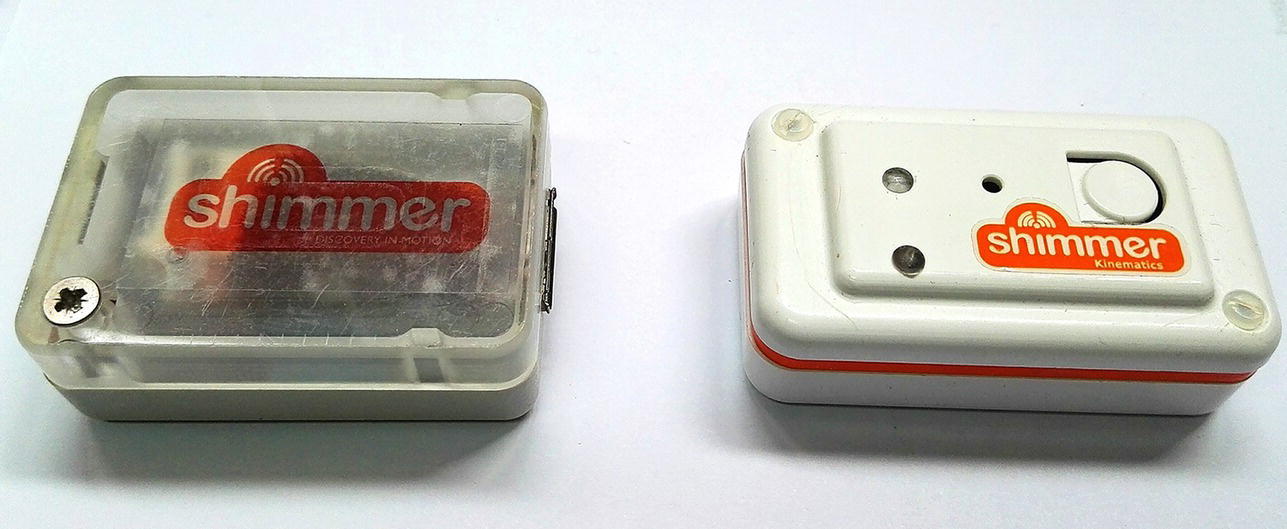
Figure 1.10 Different revisions of the Shimmer platform.
1.10 Biophysiological Signals and Sensors
There exist several and very different vital signs and biophysiological parameters. Some of them are very useful for realizing effective smart‐Health systems. Among the main parameters of interest, there are:
- blood pressure
- blood oxygenation
- blood glucose concentration
- body temperature
- brain activity
- thoracic impedance
- breathing rate
- breathing volume
- cardiac electric activity
- heart rate
- skin conductivity
- muscle activity
- posture and physical activities
There exist wearable noninvasive sensors that can be used to measure, directly or indirectly, each of the aforementioned parameters. One or multiple sensors are typically included in the basic sensor platforms and additional sensors may be integrated through expansion interfaces. In particular, the following physical sensors have been commonly used in research and industrial m‐Health systems:
- Accelerometers for measuring body movements and gestures. In recent years, the importance of these sensors increased significantly, as they perfectly fit for several medical, sport, fitness, and wellness applications. The operating principle is based on the detection of the inertia of a mass when subjected to acceleration [19]. Popular accelerometer sensors are today able to detect accelerations over the three axes, although there are also two‐axis and one‐axis accelerometers.
- Gyroscopes for measuring angular velocity. Three‐axis, two‐axis, and one‐axis gyros are commonly available. Gyroscopes are relatively immune to environmental interferences and, therefore, have been widely accepted in medical devices [20].
- Thermal sensors, a family of sensors that are used to measure temperatures or heat fluxes [19].
- Electrodes for monitoring cardiac activity (ECG), brain activity (EEG), respiratory activity (electrical impedance plethysmogram – EIP), muscle activity (electromyogram – EMG), and emotions (galvanik skin response – GSR). They must be applied directly on the skin, typically with disposable adhesive leads that contain a drop of conductive gel.
- Photoplethysmography (PPG) sensors, they are used as an indirect method to measure cardiovascular parameters such as pulse rate, blood oxygenation, and blood pressure [21]. They are realized as clips with a light emitting diode (LED) and a photosensible sensor placed at the two terminals. The clip is usually attached to the earlobe or the finger. The operating principle is based on the fact that the blood absorbs or reflects part of the emitted light and the variation of the blood volume caused by heart beats modulates the amount of transmitted or reflected light.
1.11 BSN Application Domains
Comprehensive overviews of several BSN applications can be found in Refs. [22–24]. A few surveys on wearable sensor‐based systems have been published to date. For example, in Ref. [22] the focus of the survey is on the functional perspective of the analyzed systems (i.e. what kind of applications they target). In this work, systems are divided into commercial products and research projects, and also grouped on the basis of hardware characteristics: Wired electrode‐based, smart textiles, wireless mote‐based, and based on sensors found in commercial smartphones. In another frequently cited survey work [23], the attention is focused on the hardware components and the application scenarios. Analyzed projects are classified into (i) in‐body (implantable), (ii) on‐body medical, and (iii) on‐body nonmedical systems.
Hence, to provide a different point of view, in the following, we will introduce a categorization on the main application domains in which the BSN technology can play a critical role. Moreover, a summary of some literature BSN systems is reported in Table 1.2.
Table 1.2 Summary of representative BSN systems.
| Project title | Application domain | Sensors involved | Hardware description | Node platform | Communication protocol | OS/programming language |
| Real‐time Arousal Monitor [25] | Emotion recognition | ECG, respiration, temp., GSR | Chest‐belt, skin electrodes, wearable monitor station, USB dongle | Custom | Sensors connected through wires | n/a/C‐like |
| LifeGuard [26] | Medical monitoring in space and extreme environments | ECG, blood pressure, respiration, temp., accelerometer, SpO2 | Custom microcontroller device, commercial biosensors | XPod signal conditioning unit | Bluetooth | n/a |
| Fitbit® [27] | Physical activity, sleep quality, heart monitoring | Accelerometer, heart rate | Waist/wrist‐worn device, PC USB dongle | Fitbit® node | RF proprietary | n/a |
| VitalSense® [28] | In‐ and on‐body temperature, physical activity, heart monitoring | Temp., ECG, respiration, accelerometer | Custom wearable monitor station, wireless sensors, skin electrodes, ingestible capsule | VitalSense® monitor | RF proprietary | Windows mobile |
| LiveNet [29] | Parkinson symptom, epilepsy seizure detection | ECG, Blood pressure, respiration, temp., EMG, GSR, SpO2 | PDA, microcontroller board | Custom physiological sensing board | Wires, 2.4 GHz radio, GPRS | Linux (on PDA) |
| AMON [30] | Cardiac‐respiratory diseases | ECG, blood pressure, temp., accelerometer, SpO2 | Wrist‐worn device | Custom wrist‐worn device | Sensors connected through wires –GSM/UMTS | C‐like/JAVA (on the server station) |
| MyHeart [31] | Prevention and detection of cardio vascular diseases | ECG, respiration, accelerometer | PDA, textile sensors, chest‐belt | Proprietary monitoring station | Conductive yarns, Bluetooth, GSM | Windows mobile (on the PDA) |
| Human++ [32] | General health monitoring | ECG, EMG, EEG | Low‐power BSN nodes | ASIC | 2.4 GHz radio/UWB modulation | n/a |
| HealthGear [33] | Sleep apnea detection | Heart rate, SpO2 | Custom sensing board, commercial sensors, cell phone | Custom wearable station (includes XPod signal conditioning unit) | Bluetooth | Windows mobile (on the mobile phone) |
| TeleMuse® [34] | Medical care and research | ECG, EMG, GSR | ZigBee wireless motes | Proprietary | IEEE 802.15.4/ZigBee | C‐like |
| Polar® Heart Rate Monitor [35] | Fitness and exercise | Heart rate, altimeter | Wireless chest‐belt, watch monitor | Proprietary watch monitor | Polar OwnCode® (5 kHz) – coded transmission | n/a |
As aforementioned, BSNs enable a very wide range of application scenarios. We can categorize them into different application domains:
- e‐Health
- e‐Emergency
- e‐Entertainment
- e‐Sport
- e‐Factory
- e‐Sociality
e‐Health applications include physical activity recognition, gait analysis, post‐trauma rehabilitation after surgeries, cardiac and respiratory diseases prevention and early detection, remote elderly assistance and monitoring, sleep quality monitoring and sleep apnea detection, and even emotion recognition [36].
e‐Emergency refers to applications, e.g. for supporting firefighters and response teams in large‐scale disasters due to earthquakes, landslides, and terrorist attacks [37].
e‐Entertainment domain refers to human–computer interaction systems typically based on BSNs for real‐time motion and gesture recognition, eye tracking, and, more recently, mood and emotion recognition [38, 39].
e‐Sport applications are related to the e‐Health domain, although they have a nonmedical focus. They include personal e‐fitness applications for amateur and professional athletes as well as enterprise systems for professional fitness clubs and sport teams offering advanced performance monitoring services for their athletes [40].
e‐Factory is a slowly emerging domain involving industrial process management and monitoring, and workers’ safety and collaboration support [41].
Finally, the e‐Sociality domain involves the recognition of human emotions and cognitive states to enable new forms of social interactions. An interesting example is a system for tracking interactions between two meeting people by detecting, in a collaborative fashion, handshakes and, subsequently, monitoring their social and emotional interactions [42].
1.12 Summary
This chapter has provided an overview of the current state‐of‐the‐art of the BSN domain. We have first introduced the motivations for the BSN technology. We then provided a description of the most important hardware and software requirements of BSN systems, typical m‐Health system architecture and, more in detail, the common schematic architecture of a wireless sensor node. In addition, most popular BSN network topologies, communication protocols and standards, and commercial sensor platforms have been introduced. Furthermore, particular attention has been given to the main biophysiological signals and the corresponding physical sensors for their acquisition. Finally, the chapter has provided a categorization of the most relevant BSN application domains and summarized a number of related commercial products and research projects.
References
- 1 Movassaghi, S., Abolhasan, M., Lipman, J. et al. (2014). Wireless body area networks: a survey. IEEE Communications Surveys & Tutorials 16 (3): 1658–1686.
- 2 Yang, G.Z. ed. (2006). Body Sensor Networks. Springer‐Verlag.
- 3 Gravina, R., Alinia, P., Ghasemzadeh, H., and Fortino, G. (2017). Multi‐sensor fusion in body sensor networks: state‐of‐the‐art and research challenges. Information Fusion 35: 68–80.
- 4 Kuryloski, P., Giani, A., Giannantonio, R. et al. (2009). DexterNet: an open platform for heterogeneous body sensor networks and its applications. Proceedings of the Int’l Conference on Body Sensor Networks (BSN 2009), Berkeley, CA (3–5 June 2009).
- 5 International Telecommunication Union (1992). “ARTICLE 1 – Terms and Definitions” – “Industrial, scientific and medical (ISM) applications (of radio frequency energy): operation of equipment or appliances designed to generate and use locally radio frequency energy for industrial, scientific, medical, domestic or similar purposes, excluding applications in the field of telecommunications”. http://life.itu.int/radioclub/rr/art1.pdf (accessed 10 June 2017).
- 6 Venkatesh, C. and Anandamurugan, S. (2010). Increasing the lifetime of wireless sensor networks by using AR (aggregation routing) algorithm. IJCA Special Issue on MANETs (4): 180–186.
- 7 IEEE 802.15.4 Website. http://www.ieee802.org/15/pub/tg4.html (accessed 5 June 2017).
- 8 ZigBee Website. www.zigbee.org (accessed 5 June 2017).
- 9 Bluetooth Website. www.bluetooth.com (accessed 10 June 2017).
- 10 Bluetooth Low Energy Website. https://www.bluetooth.com/what‐is‐bluetooth‐technology/how‐it‐works/le‐p2p (accessed 5 June 2017).
- 11 ANT Website. www.thisisant.com (accessed 7 June 2017).
- 12 IEEE 802.15 WPAN Task Group 6 Website. http://www.ieee802.org/15/pub/TG6.html (accessed 8 June 2017).
- 13 Augimeri, A., Fortino, G., Galzarano, S., and Gravina, R. (2011). Collaborative body sensor networks. Proceedings of the IEEE International Conference on Systems, Man and Cybertnetics (SMC2011), Anchorage, AL (9–12 October 2011).
- 14 Narayanan, R., Sarath, T., and Vineeth, V. (2016). Survey on motes used in wireless sensor networks: performance & parametric analysis. Wireless Sensor Network 8: 51–60.
- 15 Levis, P., Gay, D., and Culler, D. (2004). Bridging the Gap: Programming Sensor Networks with Application Specific Virtual Machines. UC Berkeley Tech Rep. UCB//CSD‐04‐1343.
- 16 Mica2 Datasheet. https://www.eol.ucar.edu/isf/facilities/isa/internal/CrossBow/DataSheets/mica2.pdf (accessed 10 October 2016).
- 17 TelosB Datasheet. http://www.memsic.com/userfiles/files/Datasheets/WSN/telosb_datasheet.pdf (accessed 5 June 2017).
- 18 Shimmer Platform Website. www.shimmersensing.com (accessed 11 June 2017).
- 19 Lewis, F.L. (2004). Wireless sensor networks in smart environments: technologies, protocols, applications. In: Smart Environments: Technologies, Protocols, Applications (ed. D.J. Cook and S.K. Das). Wiley Blackwell.
- 20 Madni, A.M., Wan, L.A., and Hammons, S. (1996). A microelectromechanical quartz rotational rate sensor for inertial applications. Proceedings of the IEEE Aerospatial Applications Conference, Aspen, CO (3–10 February 1996).
- 21 Fortino, G. and Giampà, V. (2010). PPG‐based methods for non invasive and continuous blood pressure measurement: an overview and development issues in body sensor networks. 2010 IEEE International Workshop on Medical Measurements and Applications, MeMeA 2010 – Proceedings, Ottawa, ON (30 April to 1 May 2010), Art. No. 5480201, pp. 10–13.
- 22 Pantelopoulos, A. and Bourbakis Nikolaos, G. (2010). A survey on wearable sensor‐based systems for health monitoring and prognosis. IEEE Transactions on Systems, Man and Cybernetics 40 (1): 1–12.
- 23 Ullah, S., Khan, P., Ullah, N. et al. (2009). A review of wireless body area networks for medical applications. International Journal of Communications, Network and System Sciences 2 (8): 797–803.
- 24 Hao, Y. and Foster, R. (2008). Wireless body sensor networks for health‐monitoring applications. Physiological Measurement 29: 27–56.
- 25 Grundlehner, B., Brown, L., Penders, J., and Gyselinckx, G. (2009). The design and analysis of a real‐time, continuous arousal monitor. Sixth International Workshop on Wearable and Implantable Body Sensor Networks, Berkeley, CA (3–5 June 2009), pp. 156–161.
- 26 Mundt, C.W., Montgomery, K.N., Udoh, U.E. et al. (2005). A multiparameter wearable physiological monitoring system for space and terrestrial applications. IEEE Transactions on Information Technology in Biomedicine 9 (3): 382–391.
- 27 Fitbit Website. www.fitbit.com (accessed 15 June 2017).
- 28 VitalSense Integrated Physiological Monitor Website. http://www.actigraphy.com/solutions/vitalsense (accessed 8 June 2017).
- 29 Sung, M., Marci, C., and Pentland, A. (2005). Wearable feedback systems for rehabilitation. Journal of NeuroEngineering and Rehabilitation 2: 17.
- 30 Anliker, U., Ward, J.A., Lukowicz, P. et al. (2004). AMON: a wearable multiparameter medical monitoring and alert system. IEEE Transactions on Information Technology in Biomedicine 8 (4): 415–427.
- 31 Luprano, J., Sola, J., Dasen, S. et al. (2006). Combination of body sensor networks and on‐body signal processing algorithms: the practical case of MyHeart project. Proceedings of the International Workshop Wearable Implantable Body Sensor Networks, Cambridge, MA (3–5 April 2006), pp. 76–79.
- 32 Gyselinckx, B., Van Hoof, C., Ryckaert, J. et al. (2005). Human++: autonomous wireless sensors for body area networks. Proceedings of the IEEE Custom Integrated Circuits Conference, San Jose, CA (18–21 September 2005), pp. 13–19.
- 33 Oliver, N. and Flores‐Mangas, F. (2006). HealthGear: a real‐time wearable system for monitoring and analyzing physiological signals. Microsoft Research. Tech. Rep. MSR‐TR‐2005‐182.
- 34 Biocontrol Systems Website. www.biocontrol.com (accessed 12 June 2017).
- 35 Polar Electro Website. www.polar.com (accessed 12 June 2017).
- 36 Gravina, R., Andreoli, A., Salmeri, A. et al. (2010). Enabling multiple BSN applications using the SPINE framework. Proceedings of the International Conference on Body Sensor Networks, BSN 2010, Singapore, pp. 228–233 (7–9 June 2010). IEEE Computer Society.
- 37 Lorincz, K., Malan, D.‐J., Fulford‐Jones, T. et al. (2004). Sensor networks for emergency response: challenges and opportunities. IEEE Pervasive Computing 3 (4): 16–23.
- 38 Terada, T. and Tanaka, K. (2010). A framework for constructing entertainment contents using flash and wearable sensors. Proceedings of the 9th International Conference on Entertainment computing, ICEC'10, Seoul, Korea (8–11 September 2010), pp. 334–341. Springer‐Verlag.
- 39 Gravina, R. and Fortino, G. (2016). Automatic methods for the detection of accelerative cardiac defense response. IEEE Transactions on Affective Computing 7 (3): 286–298.
- 40 Coyle, S., Morris, D., Lau, K. et al. (2009). Textile‐based wearable sensors for assisting sports performance. Proceedings of the International Conference on Body Sensor Networks, BSN 2009, Berkeley, CA, USA (3‐5 June 2009), pp. 228–233. IEEE Computer Society.
- 41 Huang, J.‐Y. and Tsai, C.‐H. (2007). A wearable computing environment for the security of a large‐scale factory. Proceedings of the 12th International Conference on Human‐Computer Interaction: Interaction Platforms and Techniques, HCI’07, Beijing, China (22–27 July 2007), pp. 1113–1122. Springer‐Verlag.
- 42 Augimeri, A., Fortino, G., Rege, M. et al. (2010). A cooperative approach for handshake detection based on body sensor networks. Proceedings of the IEEE International Conference on Systems, Man, and Cybernetics, SMC 2010, Istanbul, Turkey (10–13 October 2010), pp. 281–288. IEEE Press.