
Chapter 4
Power Electronics
4.1 Introduction
Power electronics is the application of solid-state electronics for the control and conversion of electric power. Power electronic converters can be found wherever there is a need to modify a form of electrical energy (i.e., change its voltage, current, or frequency). Variable-speed wind generator systems need a power electronic interface between the generator and the grid. Even for fixed-speed wind generator systems, when the energy storage system is connected to the grid power electronics devices are essential. This chapter provides a brief overview and basic understanding of various power electronics devices: rectifiers, inverters, direct current (DC)-to-DC choppers, cycloconverters, pulse width modulation (PWM)-based voltage source converters (VSCs), and current source inverters (CSIs). For detailed study, readers are referred to books of power electronics [1–5].
4.2 Power Devices
Power semiconductor devices are semiconductor devices used as switches in power electronic circuits (e.g., switch-mode power supplies). They are also called power devices or, when used in integrated circuits (ICs), power ICs. Most power semiconductor devices are used only in commutation mode (i.e., either on or off) and are therefore optimized for this. Most of them should not be used in linear operation [1].
Power semiconductor devices first appeared in 1952 with the introduction of the power diode by R. N. Hall. It was made of germanium and had a voltage capability of 200 volts and a current rating of 35 amperes. The thyristor appeared in 1957. Thyristors are able to withstand very high reverse breakdown voltage and are also capable of carrying high current. One disadvantage of the thyristor for switching circuits is that once it is “latched on” in the conducting state it cannot be turned off by external control. The thyristor turn-off is passive; that is, the power must be disconnected from the device. The first bipolar transistors devices with substantial power handling capabilities were introduced in the 1960s. These components overcame some limitations of the thyristors because they can be turned on or off with an applied signal. With the improvements brought about by metal–oxide–semiconductor technology (initially developed to produce integrated circuits), power metal–oxide–semiconductor field-effect transistors (MOSFETs) became available in the late 1970s. International Rectifier introduced a 25 A, 400 V power MOSFET in 1978. These devices allow operation at higher frequency than bipolar transistors but are limited to low-voltage applications. The insulated gate bipolar transistor (IGBT) developed in the 1980s became widely available in the 1990s. This component has the power handling capability of the bipolar transistor, with the advantages of the isolated gate drive of the power MOSFET.
Some common power devices are the power diode, thyristor, power MOSFET, and IGBT. A power diode or MOSFET operates on similar principles to its low-power counterpart but is able to carry a larger amount of current and typically is able to support a larger reverse-bias voltage in the off state. Structural changes are often made in power devices to accommodate the higher current density, higher power dissipation, or higher reverse breakdown voltage. The vast majority of discrete (i.e., non-integrated) power devices are built using a vertical structure, whereas small-signal devices employ a lateral structure. With the vertical structure, the current rating of the device is proportional to its area, and the voltage-blocking capability is achieved in the height of the die. With this structure, one of the connections of the device is located on the bottom of the semiconductor die.
4.3 Rectifier
A rectifier is an electrical device that converts alternating current (AC), which periodically reverses direction, to direct current, which is in only one direction, a process known as rectification. Rectifiers have many uses including as components of power supplies and as detectors of radio signals. Rectifiers may be made of solid-state diodes, vacuum tube diodes, mercury arc valves, and other components. When only one diode is used to rectify AC (by blocking the negative or positive portion of the waveform), the difference between the term diode and the term rectifier is merely one of usage—that is, the term rectifier describes a diode that is being used to convert AC to DC. Almost all rectifiers comprise a number of diodes in a specific arrangement for more efficiently converting AC to DC than is possible with only one diode. Before the development of silicon semiconductor rectifiers, vacuum tube diodes and copper(I) oxide or selenium rectifier stacks were used. Figures 4.1, 4.2, and 4.3 show ordinary thyristor-based basic half-wave rectifier, full-wave rectifier, and six-pulse rectifier circuits and their associated output voltage waveforms, respectively.
4.4 Inverter
An inverter is an electrical device that converts DC to AC; the converted AC can be at any required voltage and frequency with the use of appropriate transformers, switching, and control circuits. Solid-state inverters have no moving parts and are used in a wide range of applications, from small switching power supplies in computers to large electric utility high-voltage direct current applications that transport bulk power. Inverters are commonly used to supply AC power from DC sources such as solar panels or batteries.

Figure 4.1 Half-wave rectifier circuit and output waveforms.
There are two main types of inverters. The output of a modified sine wave inverter is similar to a square wave output except that the output goes to zero volts for a time before switching positive or negative. It is simple and low cost and is compatible with most electronic devices, except for sensitive or specialized equipment, for example, certain laser printers. A pure sine wave inverter produces a nearly perfect sine wave output (<3% total harmonic distortion) that is essentially the same as utility-supplied grid power. Thus, it is compatible with all AC electronic devices. This is the type used in grid-tie inverters. Its design is more complex and costs 5 to 10 times more per unit power. The electrical inverter is a high-power electronic oscillator. It is so named because early mechanical AC-to-DC converters were made to work in reverse and thus were “inverted” to convert DC to AC. Figure 4.4 shows a basic inverter circuit.

Figure 4.2 Full-wave rectifier circuit and output waveforms.

Figure 4.3 Six-pulse rectifier circuit and output waveforms.

Figure 4.4 Basic inverter circuit.
4.5 Chopper
A DC-to-DC converter is an electronic circuit that converts a source of DC from one voltage level to another. The variable DC voltage is controlled by chopping the input voltage by varying the on and off times (duty cycle) of a converter, and the type of the converter capable of such a function is known as a chopper. A schematic diagram of the chopper is shown in Figure 4.5. The control voltage to its gate is vc. The chopper is on for a time ton, and its off time is toff . Its frequency of operation is
and its duty cycle is defined as
The output voltage across the load during the on time of the switch is equal to the difference between the source voltage Vs and the voltage drop across the power switch. Assuming that the switch is ideal, with zero voltage drop, the average output voltage Vdc is given as
where Vs is the source voltage.

Figure 4.5 Chopper schematic and its waveforms.
Varying the duty cycle changes the output voltage. Note that the output voltage follows the control voltage, as shown in Figure 4.5, signifying that the chopper is the voltage amplifier. The duty cycle d can be changed in two ways [2]:
By keeping the switching or chopping frequency constant and varying the on time to get a changing duty cycle.
Keeping the on time constant and varying the chopping frequency to obtain various values of the duty cycle.
A constant switching frequency has the advantages of predetermined switching losses of the chopper, enabling optimal design of the cooling for the power circuit, and predetermined harmonic contents, leading to an optimal input filter. Both of these advantages are lost by varying the switching frequency of the chopper; hence, this technique for chopper control is not prevalent in practice.
DC-to-DC converters are important in portable electronic devices such as cellular phones and laptop computers, which are supplied primarily with battery power. Such electronic devices often contain several sub-circuits, each with its own voltage level requirement different from that supplied by the battery or an external supply (sometimes higher or lower than the supply voltage). Additionally, the battery voltage declines as its stored power is drained. Switched DC-to-DC converters offer a method to increase voltage from a partially lowered battery voltage, thereby saving space instead of using multiple batteries to accomplish the same thing.
Most DC-to-DC converters also regulate the output voltage. Some exceptions include high-efficiency light-emitting diode (LED) power sources, which are a kind of DC-to-DC converter that regulates the current through the LEDs, and simple charge pumps, which double or triple the input voltage. Electronic switch-mode DC-to-DC converters convert one DC voltage level to another by storing the input energy temporarily and then releasing that energy to the output at a different voltage. The storage may be in either magnetic field storage components (inductors, transformers) or electric field storage components (capacitors). This conversion method is more power efficient (often 75 to 98%) than linear voltage regulation (which dissipates unwanted power as heat). This efficiency is beneficial to increasing the running time of battery-operated devices. The efficiency has increased since the late 1980s due to the use of power field-effect transistors (FETs), which are able to switch at high frequency more efficiently than power bipolar transistors, which incur more switching losses and require a more complicated drive circuit. Another important innovation in DC-to-DC converters is the use of synchronous rectification replacing the flywheel diode with a power FET with low “on” resistance, thereby reducing switching losses.
Most DC-to-DC converters are designed to move power in only one direction: from the input to the output. However, all switching regulator topologies can be made bidirectional by replacing all diodes with independently controlled active rectification. A bidirectional converter can move power in either direction, which is useful in applications requiring regenerative braking. Drawbacks of switching converters include complexity, electronic noise (i.e., electromagnetic interference [EMI] or radio frequency interference [RFI]), and to some extent cost, although this has come down with advances in chip design.
DC-to-DC converters are now available as integrated circuits needing minimal additional components and also as a complete hybrid circuit component, ready for use within an electronic assembly. A converter where output voltage is lower than the input voltage is called a buck converter. A converter that outputs a voltage higher than the input voltage is called a boost converter. A buck–boost converter provides an output voltage that may be less than or greater than the input voltage (hence the name buck–boost); the output voltage polarity is opposite to that of the input voltage. Similar to the buck–boost converter, the cuk converter provides an output voltage that is less than or greater than the input voltage, but the output voltage polarity is opposite to that of the input voltage. Figure 4.6 shows various chopper circuits.
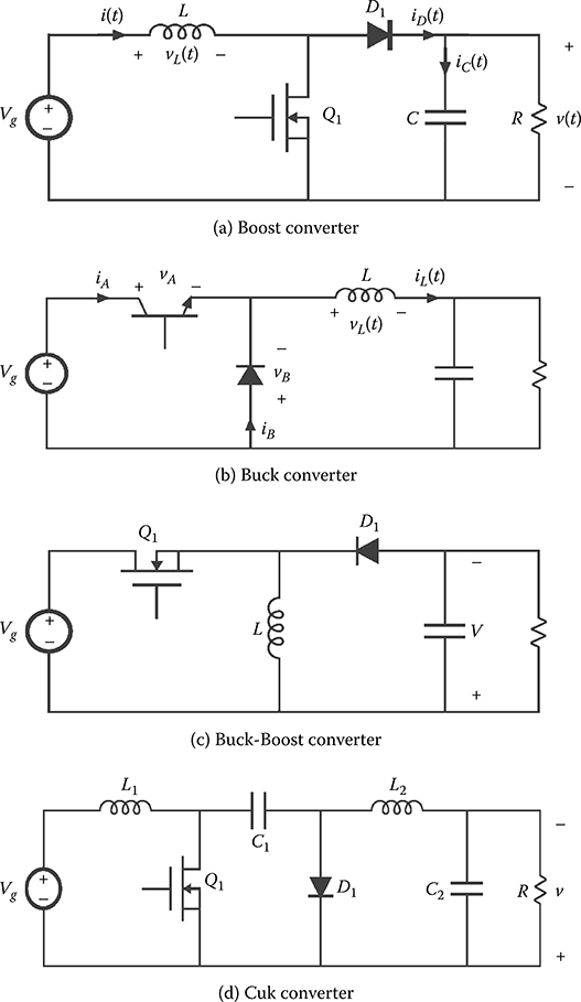
Figure 4.6 DC–DC converters.
4.6 Cycloconverter
A cycloconverter or a cycloinverter converts an AC waveform, such as the mains supply, to another AC waveform of a lower frequency, synthesizing the output waveform from segments of the AC supply without an intermediate direct-current link. They are most commonly used in three-phase applications. In most power systems, the amplitude and the frequency of input voltage to a cycloconverter tend to be fixed values, whereas both the amplitude and the frequency of output voltage of a cycloconverter tend to be variable. The output frequency of a three-phase cycloconverter must be less than about one-third to one-half the input frequency [1]. The quality of the output waveform improves if more switching devices are used (a higher pulse number). Cycloverters are used in very large variable frequency drives, with ratings of several megawatts. Figure 4.7 shows the connection of the thyristors in a cycloconverter.
Typical applications of a cycloconverter include to control the speed of an AC traction motor and to start a synchronous motor. Most of these cycloconverters have a high power output—on the order of a few megawatts—and silicon-controlled rectifiers (SCRs) are used in these circuits. By contrast, low-cost, low-power cycloconverters for low-power AC motors are also in use, and many such circuits tend to use TRIACs in place of SCRs. Unlike an SCR, which conducts in only one direction, a TRIAC is capable of conducting in either direction, but it is also a three-terminal device. The use of a cycloconverter is not as common as that of an inverter, and a cycloinverter is rarely used. However, it is common in very high-power applications such as for ball mills in ore processing, cement kilns, and azimuth thrusters in large ships.
The switching of the AC waveform creates noise, or harmonics, in the system that depends mostly on the frequency of the input waveform. These harmonics can damage sensitive electronic equipment. If the relative difference between the input and output waveforms is small, then the converter can produce subharmonics. Subharmonic noise occurs at a frequency below the output frequency and cannot be filtered by load inductance. This limits the output frequency relative to the input. These limitations make cycloconverters often inferior to a DC link converter system for most applications.
4.7 Pulse Width Modulation Scheme
PWM is a commonly used technique for controlling power to inertial electrical devices, made practical by modern electronic power switches. The average value of voltage (and current) fed to the load is controlled by turning the switch between supply and load on and off at a fast pace. The longer the switch is on compared with the off periods, the higher the power supplied to the load is. The PWM switching frequency has to be much faster than what would affect the load, i.e., the device that uses the power. Typically switchings have to be done several times a minute in an electric stove, 120 Hz in a lamp dimmer, from a few kilohertz (kHz) to tens of kHz for a motor drive, and well into the tens or hundreds of kHz in audio amplifiers and computer power supplies. The term duty cycle describes the proportion of on time to the regular interval or period of time; a low duty cycle corresponds to low power, because the power is off for most of the time. Duty cycle is expressed in percent, 100% being fully on. Figure 4.8 shows a figure representing a pulse width modulation scheme.
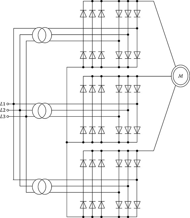
Figure 4.7 Connection of the thyristors in a cycloconverter.
There are various PWM schemes. Well known among these are sinusoidal PWM, hysteresis PWM, space vector modulation (SVM), and “optimal” PWM techniques based on the optimization of certain performance criteria, such as selective harmonic elimination, increasing efficiency, and minimization of torque pulsation. While sinusoidal and hysteresis PWM can be implemented using analog techniques, the remaining PWM techniques require the use of a microprocessor [1–5].
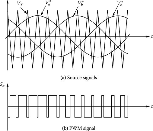
Figure 4.8 Pulse-width modulation scheme.
A modulation scheme especially developed for drives is the direct flux and torque control (DTC). A two-level hysteresis controller is used to define the error of the stator flux. The torque is compared with its reference value and is fed into a three-level hysteresis comparator. The phase angle of the instantaneous stator flux linkage space phasor together with the torque and flux error state is used in a switching table for the selection of an appropriate voltage state applied to the motor. Usually, there is no fixed pattern modulation in process or fixed voltage-to-frequency relation in the DTC. The DTC approach is similar to the Field Oriented Control (FOC) with hysteresis PWM. However, it takes the interaction among the three phases into account.
The main advantage of PWM is that power loss in the switching devices is very low. When a switch is off there is practically no current, and when it is on there is almost no voltage drop across the switch. Power loss, being the product of voltage and current, is thus close to zero in both cases. PWM also works well with digital controls, which because of their on–off nature can easily set the needed duty cycle. PWM has also been used in certain communication systems where its duty cycle has been used to convey information over a communications channel.
Usually, the on and off states of the power switches in one inverter leg are always opposite. Therefore, the inverter circuit can be simplified into three two-position switches. Either the positive or the negative DC bus voltage is applied to one of the motor phases for a short time. PWM is a method whereby the switched voltage pulses are produced for different output frequencies and voltages. A typical modulator produces an average voltage value equal to the reference voltage within each PWM period. Considering a very short PWM period, the reference voltage is reflected by the fundamental of the switched pulse pattern.
Apart from the fundamental wave, the voltage spectrum at the motor terminals consists of many higher harmonics. The interaction between the fundamental motor flux wave and the fifth and seventh harmonic currents produces a pulsating torque six times that of the fundamental supply frequency. Similarly, the eleventh and thirteenth harmonics produce a pulsating torque twelve times that of the fundamental supply frequency. Furthermore, harmonic currents and skin effect increase copper losses, which leads to motor derating. However, the motor reactance acts as a low-pass filter and substantially reduces high-frequency current harmonics. Therefore, the motor flux (Induction Motor [IM] & Permanent Magnet Synchronous Motor [PMSM]) is in good approximation sinusoidal and the contribution of harmonics to the developed torque is negligible. To minimize the effect of harmonics on the motor performance, the PWM frequency should be as high as possible. However, the PWM frequency is restricted by the control unit (resolution) and the switching device capabilities, for example, due to switching losses and dead time distorting the output voltage.
4.8 PWM VSC
The PWM VSC provides a power electronic interface between the AC power system and superconducting coil. In the PWM generator, the sinusoidal reference signal is phase modulated by means of the phase angle, a, of the VSC output AC voltage. The modulated sinusoidal reference signal is compared with the triangular carrier signal to generate the gate signals for the IGBTs. Figure 4.9 shows a basic PWM-based voltage source converter circuit consisting of a Wye-Delta transformer, a six-pulse PWM rectifier/inverter using an IGBT, and a DC link capacitor [6].
107
4.9 Current Source Inverter
With the availability of modern gate turn-off switching devices at increasing power levels and the introduction of advanced multilevel power converter topologies, the classical CSI topology has been virtually replaced by the voltage source inverter (VSI), even in applications up to several MW. However, SCR-based CSI systems are still being used for very high-power synchronous motor drives and utility power systems due to various performance advantages [5].

Figure 4.9 Basic configuration of PWM voltage source converter (VSC).
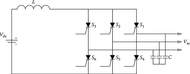
Figure 4.10 Schematic of a classical SCR-based CSI.
CSI topologies have certain performance advantages in terms of ruggedness and their ability to feed capacitive and low-impedance loads with ease. As high-power permanent magnet motors with extremely low armature winding inductance are becoming more common and the electrolytic capacitor of a VSI becoming notorious as the largest and least reliable among inverter components, a renewed interest in CSI systems may be expected to follow.
The classical CSI based on SCRs (Figure 4.10) has several disadvantages, stemming simply from the fact that SCRs cannot be turned off from the gate. Hence, their operation has been typically limited to six-step switching and application to active loads capable of operation at leading power factor. Six-step switching leads to a large amount of harmonics in the load voltage and current. Thus, they have been naturally bucked by the trend of increasing demands of performance. Furthermore, they are not well suited to drive induction motors, which must operate at a lagging power factor. These reasons have generally impeded their widespread application. Replacement of the SCR with a GTO device would allow turn-off capability and will result in the extension of operation to loads with wider power factor and even PWM capability. However, due the limited switching speeds of GTOs this approach has seen limited application. More commonly, GTO devices have been adapted to operate in multilevel VSI systems. Switching throws in a CSI realized using bidirectional voltage blocking and unidirectional current carrying devices have been well known. Figure 4.11 illustrates such a realization using IGBT devices in series with diodes. This topology is plagued with low efficiency due to current flow through the series connection of two semiconductors per throw.
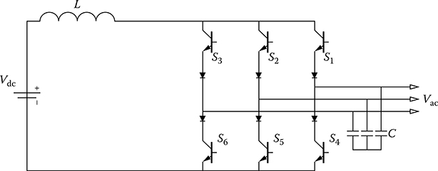
Figure 4.11 Schematic of a CSI using IGBT and series diodes.
The three-phase PWM CSI is composed of a bridge with six reverse blocking switches (S1–S6), which each has a transistor and a series diode. The DC link contains an inductor as the main energy storage component, and, at the output, a C (capacitor) filter smoothens the pulsed phase currents from the DC link. The topology is capable of operating at moderate maximum power point (MPP) voltages (ca. 200–400 V) due to its inherent voltage-boost characteristic. However, to keep the volt–second balance across the DC inductor, there is an upper DC voltage limit, which is defined as the absolute minimum of the rectified phase-to-phase voltage.
CSIs, typically supplied from controlled rectifiers with closed-loop current control, can transfer the electric power in both directions and are characterized by a fast response to the phase command for the vector of output current. Operated in the square-wave mode, CSIs are more efficient than the PWM VSIs. Also, the power circuit of the CSI is simpler and more robust than that of the VSI, thanks to the absence of freewheeling diodes and, because of the large DC–link inductance and current control in the rectifier, the inherent protection from overcurrents. On the other hand, the same inductance slows down the response to current magnitude control commands and can cause a dangerous overvoltage if the current path is broken. The square-wave output current waveforms, rich in low-order harmonics, are the most obvious disadvantage of CSIs. In addition, the same waveforms produce voltage spikes in the stator leakage inductance of the supplied motor, potentially dangerous for the winding insulation. PWM CSIs, equipped with output capacitors that shunt ripple currents, offer a partial solution to these problems. However, PWM CSIs have their weaknesses too, such as the increased size and cost, reduced efficiency associated with the PWM operation, greater complexity of the control algorithm, and susceptibility to resonance between the output capacitors and load inductances.
4.10 Chapter Summary
This chapter provides a brief overview of power electronics devices—such as rectifiers, inverters, DC-to-DC choppers, cycloconverters, PWM-based voltage source converters, and current source inverters—which are essential components of grid-connected wind generator systems. In the case of a variable-speed wind generator system, power electronics interface is used between the terminal of the wind generator and the grid point. Again, in the case of the fixed-speed wind generator system, power electronics interface is necessary for the energy storage system. Thus, the basic understanding of the operations and characteristic of the power electronics devices are essential. These concepts will be fully used in Chapters 5, 7, 8, and 9.
References
1. M. H. Rashid, Power electronics, 3d ed., Prentice Hall, 2004.
2. R. Krishnan, Electric motor drives: Modeling, analysis, and control, Prentice Hall, 2001.
3. N. Mohan, Electric drives: An integrative approach, MNPERE, 2000.
4. V. Subrahmanyam, Electric drives: Concepts and applications, McGraw-Hill, 1994.
5. B. Wu, High-power converters and AC drives, IEEE Press, 2006.
6. M. H. Ali, J. Tamura, and B. Wu, “SMES strategy to minimize frequency fluctuations of wind generator system,” Proceedings of the 34th annual conference of the IEEE Industrial Electronics Society (IECON 2008), November 10–13, 2008, Orlando, FL, pp. 3382–3387.
7. V. Blasko and V. Kaura, “A new mathematical model and control of a three-phase AC-DC voltage source converter,” IEEE Trans. Power Electron., vol. 12, no. 1, pp. 116–123, January 1997.
8. J. W. Choi and S. K. Sul, “Fast current controller in three-phase AC/DC boost converter using d-q axis cross-coupling,” IEEE Trans. Power Electronics, vol. 13, no. 1, pp. 179–185, January 1998.
9. R. Wu, S. B. Dewan, and G. R. Slemon, “Analysis of an AC-to-DC voltage source converter using PWM with fixed switching frequency,” IEEE Trans. Ind. Appl., vol. 27, no. 2, pp. 355–364, March–April 1991.
10. T. Noguchi, H. Tomiki, S. Kondo, and I. Takahashi, “Direct power control of PWM converter without power-source voltage sensor,” IEEE Trans. Ind. Appl., vol. 34, no. 3, pp. 473–479, May–June 1998.
11. M. Malinowski, M. P. Kazmierkowski, S. Hansen, F. Blaabjerg, and G. D. Marques, “Virtual-flux-based direct power control of three-phase PWM rectifier,” IEEE Trans. Ind. Appl., vol. 37, no. 4, pp. 1019–1027, July–August 2001.
12. T. Ohnuki, O. Miyashita, P. Lataire, and G. Maggetto, “Control of a three-phase PWM rectifier using estimated AC-side and DC-side voltages,” IEEE Trans. Power Electron., vol. 14, no. 2, pp. 222–226, March 1999.
13. J. Rodríguez, S. Bernet, B. Wu, J. Pontt, and S. Kouro, “Multilevel voltage-source-converter topologies for industrial medium-voltage drives,” IEEE Trans. Ind. Electron., vol. 54, no. 6, pp. 2930–2945, December 2007.
14. M. Salo and H. Tuusa, “A vector-controlled PWM current-source-inverter fed induction motor drive with a new stator current control method,” IEEE Trans. Ind. Electron., vol. 52, no. 2, pp. 523–531, April 2005.
15. P. Cancelliere, V. D. Colli, R. Di Stefano, and F. Marignetti, “Modeling and control of a zero-current-switching DC/AC current-source inverter,” IEEE Trans. Ind. Electron., vol. 54, no. 4, pp. 2106–2119, August 2007.
16. M. Hombu, S. Ueda, and A. Ueda, “A current source GTO inverter with sinusoidal inputs and outputs,” IEEE Trans. Ind. Appl., vol. IA-23, no. 2, pp. 247–255, March 1987.
17. N. R. Zargari, S. C. Rizzo et al., “A new current-source converter using a symmetric gate-commutated thyristor (SGCT),” IEEE Trans. Ind. Appl., vol. 37, no. 3, pp. 896–903, May–June 2001.
18. S. Rees, “New cascaded control system for current-source rectifiers,” IEEE Trans. Ind. Electron., vol. 52, no. 3, pp. 774–784, June 2005.
19. B. M. Han and S. I. Moon, “Static reactive-power compensator using soft switching current-source inverter,” IEEE Trans. Ind. Electron., vol. 48, no. 6, pp. 1158–1165, December 2001.
20. M. Salo and H. Tuusa, “A new control system with a control delay compensation for a current-source active power filter,” IEEE Trans. Ind. Electron., vol. 52, no. 6, pp. 1616–1624, December 2005.
21. J. R. Espinoza, G. Joos, J. I. Guzman, L. A. Moran, and R. P. Burgos, “Selective harmonic elimination and current/voltage control in current/voltage-source topologies: A unified approach,” IEEE Trans. Ind. Electron., vol. 48, no. 1, pp. 71–81, February 2001.
22. J. Ma, B. Wu, and S. Rizzo, “A space vector modulated CSI-based AC drive for multimotor applications,” IEEE Trans. Power Electron., vol. 16, no. 4, pp. 535–544, July 2001.
23. Y. Suh, J. K. Steinke, and P. K. Steimer, “Efficiency comparison of voltage-source and current-source drive systems for medium-voltage applications,” IEEE Trans. Ind. Electron., vol. 54, no. 5, pp. 2521–2531, October 2007.
24. J. Rodríguez, L. Moran, J. Pontt, R. Osorio, and S. Kouro, “Modeling and analysis of common-mode voltages generated in medium voltage PWMCSI drives,” IEEE Trans. Power Electron., vol. 18, no. 3, pp. 873–879, May 2003.
25. R. Emery and J. Eugene, “Harmonic losses in LCI-fed synchronous motors,” IEEE Trans. Ind. Appl., vol. 38, no. 4, pp. 948–954, July–August 2002.
26. R. Bhatia, H. Krattiger, A. Bonanini, D. Schafer, J. T. Inge, and G. H. Sydnor, “Adjustable speed drive using a single 135,000 HP synchronous motor,” IEEE Trans. Energy Conversion, vol. 14, no. 3, pp. 571–576, September 1999.
27. S. Kwak and H. A. Toliyat, “Current-source-rectifier topologies for sinusoidal supply current: Theoretical studies and analyses,” IEEE Trans. Ind. Electron., vol. 53, no. 3, pp. 984–987, June 2006.
28. P. Syam, G. Bandyopadhyay, P. K. Nandi, and A. K. Chattopadhyay, “Simulation and experimental study of interharmonic performance of a cycloconverter-fed synchronous motor drive,” IEEE Trans. Energy. Conversion, vol. 19, no. 2, pp. 325–332, June 2004.
29. Y. Liu, G. T. Heydt, and R. F. Chu, “The power quality impact of cycloconverter control strategies,” IEEE Trans. Power Del., vol. 20, no. 2, pp. 1711– 1718, April 2005.
30. Z. Wang and Y. Liu, “Modeling and simulation of a cycloconverter drive system for harmonic studies,” IEEE Trans. Ind. Electron., vol. 47, no. 3, pp. 533–541, June 2000.
31. F. Zhang, L. Du, F. Z. Peng, and Z. Qian, “A new design method for high-power high-efficiency switched-capacitor DCDC converters,” IEEE Trans. Power Electron., vol. 23, pp. 832–840, March 2008.
32. J. Pinheiro and I. Barbi, “The three-level ZVS-PWM DC-to-DC converter,” IEEE Trans. Power Electron., vol. 8., pp. 486–492, October 1993.
33. H. Wu and X. He, “Single phase three-level power factor correction circuit with passive lossless snubber,” IEEE Trans. Power Electron., vol. 17, pp. 946–953, 2002.
34. J. P. Rodrigues, S. A. Mussa, I. Barbi, and A. J. Perin, “Three-level zero-voltage switching pulse-width modulation DCDC boost converter with active clamping,” IET Power Electronics, vol. 3, pp. 345–354, 2010.
35. J. C. Rosas-Caro, J. M. Ramirez, F. Z. Peng, and A. Valderrabano, “A DC-DC multilevel boost converter,” IET Power Electronics, vol. 3, pp. 129–137, 2010.
36. M. Shen, F. Z. Peng, and L. M. Tolbert, “Multilevel DC–DC power conversion system with multiple DC sources,” IEEE Trans. Power Electron., vol. 23, pp. 420–426, January 2008.
37. F. H. Khan and L.M. Tolbert, “Multiple-load-source integration in a multilevel modular capacitor-clamped DC–DC converter featuring fault tolerant capability,” IEEE Trans. Power Electron., vol. 24, pp. 14–24, January 2009.
38. X. Yuan and I. Barbi, “Fundamentals of a new diode clamping multilevel inverter,” IEEE Trans. Power Electron., vol. 15, pp. 711–718, July 2000.
39. F. Z. Peng, “A generalized multilevel inverter topology with self voltage balancing,” IEEE Trans. Ind. Application, vol. 37, pp. 611–618, March–April 2001.
40. G. P. Adam, S. J. Finney, A. M. Massoud, and B. W. Williams, “Capacitor balance issues of the diode-clamped multilevel inverter operated in a quasi two-state mode,” IEEE Trans. Ind. Electron., vol. 55, pp. 3088–3099, 2008.
41. S. Busquets-Monge, S. Alepuz, J. Bordonau, and J. Peracaula, “Voltage balancing control of diode-clamped multilevel converters with passive front-ends,” IEEE Trans. Power Electron., vol. 23, pp. 1751–1758, 2008.
42. N. Rouger and J.-C. Crebier, “Toward generic fully integrated gate driver power supplies,” IEEE Trans. Power Electron., vol. 23, pp. 2106–2114, July 2008.