
Chapter 10
Management, diagnostics, and tracing
This chapter describes fundamental mechanisms in the Microsoft Windows operating system that are critical to its management and configuration. In particular, we describe the Windows registry, services, the Unified Background process manager, and Windows Management Instrumentation (WMI). The chapter also presents some fundamental components used for diagnosis and tracing purposes like Event Tracing for Windows (ETW), Windows Notification Facility (WNF), and Windows Error Reporting (WER). A discussion on the Windows Global flags and a brief introduction on the kernel and User Shim Engine conclude the chapter.
The registry
The registry plays a key role in the configuration and control of Windows systems. It is the repository for both systemwide and per-user settings. Although most people think of the registry as static data stored on the hard disk, as you’ll see in this section, the registry is also a window into various in-memory structures maintained by the Windows executive and kernel.
We’re starting by providing you with an overview of the registry structure, a discussion of the data types it supports, and a brief tour of the key information Windows maintains in the registry. Then we look inside the internals of the configuration manager, the executive component responsible for implementing the registry database. Among the topics we cover are the internal on-disk structure of the registry, how Windows retrieves configuration information when an application requests it, and what measures are employed to protect this critical system database.
Viewing and changing the registry
In general, you should never have to edit the registry directly. Application and system settings stored in the registry that require changes should have a corresponding user interface to control their modification. However, as we mention several times in this book, some advanced and debug settings have no editing user interface. Therefore, both graphical user interface (GUI) and command-line tools are included with Windows to enable you to view and modify the registry.
Windows comes with one main GUI tool for editing the registry—Regedit.exe—and several command-line registry tools. Reg.exe, for instance, has the ability to import, export, back up, and restore keys, as well as to compare, modify, and delete keys and values. It can also set or query flags used in UAC virtualization. Regini.exe, on the other hand, allows you to import registry data based on text files that contain ASCII or Unicode configuration data.
The Windows Driver Kit (WDK) also supplies a redistributable component, Offregs.dll, which hosts the Offline Registry Library. This library allows loading registry hive files (covered in the “Hives” section later in the chapter) in their binary format and applying operations on the files themselves, bypassing the usual logical loading and mapping that Windows requires for registry operations. Its use is primarily to assist in offline registry access, such as for purposes of integrity checking and validation. It can also provide performance benefits if the underlying data is not meant to be visible by the system because the access is done through local file I/O instead of registry system calls.
Registry usage
There are four principal times at which configuration data is read:
■ During the initial boot process, the boot loader reads configuration data and the list of boot device drivers to load into memory before initializing the kernel. Because the Boot Configuration Database (BCD) is really stored in a registry hive, one could argue that registry access happens even earlier, when the Boot Manager displays the list of operating systems.
■ During the kernel boot process, the kernel reads settings that specify which device drivers to load and how various system elements—such as the memory manager and process manager—configure themselves and tune system behavior.
■ During logon, Explorer and other Windows components read per-user preferences from the registry, including network drive-letter mappings, desktop wallpaper, screen saver, menu behavior, icon placement, and, perhaps most importantly, which startup programs to launch and which files were most recently accessed.
■ During their startup, applications read systemwide settings, such as a list of optionally installed components and licensing data, as well as per-user settings that might include menu and toolbar placement and a list of most-recently accessed documents.
However, the registry can be read at other times as well, such as in response to a modification of a registry value or key. Although the registry provides asynchronous callbacks that are the preferred way to receive change notifications, some applications constantly monitor their configuration settings in the registry through polling and automatically take updated settings into account. In general, however, on an idle system there should be no registry activity and such applications violate best practices. (Process Monitor, from Sysinternals, is a great tool for tracking down such activity and the applications at fault.)
The registry is commonly modified in the following cases:
■ Although not a modification, the registry’s initial structure and many default settings are defined by a prototype version of the registry that ships on the Windows setup media that is copied onto a new installation.
■ Application setup utilities create default application settings and settings that reflect installation configuration choices.
■ During the installation of a device driver, the Plug and Play system creates settings in the registry that tell the I/O manager how to start the driver and creates other settings that configure the driver’s operation. (See Chapter 6, “I/O system,” in Part 1 for more information on how device drivers are installed.)
■ When you change application or system settings through user interfaces, the changes are often stored in the registry.
Registry data types
The registry is a database whose structure is similar to that of a disk volume. The registry contains keys, which are similar to a disk’s directories, and values, which are comparable to files on a disk. A key is a container that can consist of other keys (subkeys) or values. Values, on the other hand, store data. Top-level keys are root keys. Throughout this section, we’ll use the words subkey and key interchangeably.
Both keys and values borrow their naming convention from the file system. Thus, you can uniquely identify a value with the name mark, which is stored in a key called trade, with the name trademark. One exception to this naming scheme is each key’s unnamed value. Regedit displays the unnamed value as (Default).
Values store different kinds of data and can be one of the 12 types listed in Table 10-1. The majority of registry values are REG_DWORD, REG_BINARY, or REG_SZ. Values of type REG_DWORD can store numbers or Booleans (true/false values); REG_BINARY values can store numbers larger than 32 bits or raw data such as encrypted passwords; REG_SZ values store strings (Unicode, of course) that can represent elements such as names, file names, paths, and types.
Table 10-1 Registry value types
Value Type |
Description |
|---|---|
REG_NONE |
No value type |
REG_SZ |
Fixed-length Unicode string |
REG_EXPAND_SZ |
Variable-length Unicode string that can have embedded environment variables |
REG_BINARY |
Arbitrary-length binary data |
REG_DWORD |
32-bit number |
REG_DWORD_BIG_ENDIAN |
32-bit number, with high byte first |
REG_LINK |
Unicode symbolic link |
REG_MULTI_SZ |
Array of Unicode NULL-terminated strings |
REG_RESOURCE_LIST |
Hardware resource description |
REG_FULL_RESOURCE_DESCRIPTOR |
Hardware resource description |
REG_RESOURCE_REQUIREMENTS_LIST |
Resource requirements |
REG_QWORD |
64-bit number |
The REG_LINK type is particularly interesting because it lets a key transparently point to another key. When you traverse the registry through a link, the path searching continues at the target of the link. For example, if Root1Link has a REG_LINK value of Root2RegKey and RegKey contains the value RegValue, two paths identify RegValue: Root1LinkRegValue and Root2RegKeyRegValue. As explained in the next section, Windows prominently uses registry links: three of the six registry root keys are just links to subkeys within the three nonlink root keys.
Registry logical structure
You can chart the organization of the registry via the data stored within it. There are nine root keys (and you can’t add new root keys or delete existing ones) that store information, as shown in Table 10-2.
Table 10-2 The nine root keys
Root Key |
Description |
|---|---|
HKEY_CURRENT_USER |
Stores data associated with the currently logged-on user |
HKEY_CURRENT_USER_LOCAL_SETTINGS |
Stores data associated with the currently logged-on user that are local to the machine and are excluded from a roaming user profile |
HKEY_USERS |
Stores information about all the accounts on the machine |
HKEY_CLASSES_ROOT |
Stores file association and Component Object Model (COM) object registration information |
HKEY_LOCAL_MACHINE |
Stores system-related information |
HKEY_PERFORMANCE_DATA |
Stores performance information |
HKEY_PERFORMANCE_NLSTEXT |
Stores text strings that describe performance counters in the local language of the area in which the computer system is running |
HKEY_PERFORMANCE_TEXT |
Stores text strings that describe performance counters in US English. |
HKEY_CURRENT_CONFIG |
Stores some information about the current hardware profile (deprecated) |
Why do root-key names begin with an H? Because the root-key names represent Windows handles (H) to keys (KEY). As mentioned in Chapter 1, “Concepts and tools” of Part 1, HKLM is an abbreviation used for HKEY_LOCAL_MACHINE. Table 10-3 lists all the root keys and their abbreviations. The following sections explain in detail the contents and purpose of each of these root keys.
Table 10-3 Registry root keys
Root Key |
Abbreviation |
Description |
Link |
|---|---|---|---|
HKEY_CURRENT_USER |
HKCU |
Points to the user profile of the currently logged-on user |
Subkey under HKEY_USERS corresponding to currently logged-on user |
HKEY_CURRENT_USER_LOCAL_SETTINGS |
HKCULS |
Points to the local settings of the currently logged-on user |
Link to HKCUSoftwareClassesLocal Settings |
HKEY_USERS |
HKU |
Contains subkeys for all loaded user profiles |
Not a link |
HKEY_CLASSES_ROOT |
HKCR |
Contains file association and COM registration information |
Not a direct link, but rather a merged view of HKLMSOFTWAREClasses and HKEY_USERS<SID>SOFTWAREClasses |
HKEY_LOCAL_MACHINE |
HKLM |
Global settings for the machine |
Not a link |
HKEY_CURRENT_CONFIG |
HKCC |
Current hardware profile |
HKLMSYSTEMCurrentControlSetHardware ProfilesCurrent |
HKEY_PERFORMANCE_DATA |
HKPD |
Performance counters |
Not a link |
HKEY_PERFORMANCE_NLSTEXT |
HKPNT |
Performance counters text strings |
Not a link |
HKEY_PERFORMANCE_TEXT |
HKPT |
Performance counters text strings in US English |
Not a link |
HKEY_CURRENT_USER
The HKCU root key contains data regarding the preferences and software configuration of the locally logged-on user. It points to the currently logged-on user’s user profile, located on the hard disk at Users<username>Ntuser.dat. (See the section “Registry internals” later in this chapter to find out how root keys are mapped to files on the hard disk.) Whenever a user profile is loaded (such as at logon time or when a service process runs under the context of a specific username), HKCU is created to map to the user’s key under HKEY_USERS (so if multiple users are logged on in the system, each user would see a different HKCU). Table 10-4 lists some of the subkeys under HKCU.
Table 10-4 HKEY_CURRENT_USER subkeys
Subkey |
Description |
|---|---|
AppEvents |
Sound/event associations |
Console |
Command window settings (for example, width, height, and colors) |
Control Panel |
Screen saver, desktop scheme, keyboard, and mouse settings, as well as accessibility and regional settings |
Environment |
Environment variable definitions |
EUDC |
Information on end-user defined characters |
Keyboard Layout |
Keyboard layout setting (for example, United States or United Kingdom) |
Network |
Network drive mappings and settings |
Printers |
Printer connection settings |
Software |
User-specific software preferences |
Volatile Environment |
Volatile environment variable definitions |
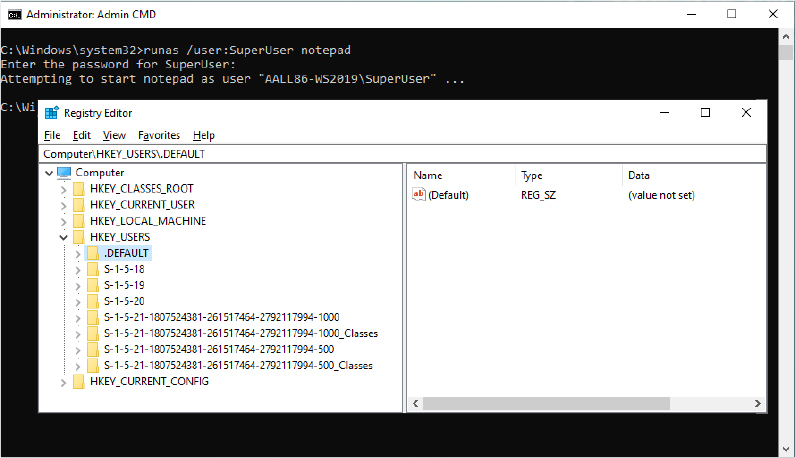
HKEY_USERS
HKU contains a subkey for each loaded user profile and user class registration database on the system. It also contains a subkey named HKU.DEFAULT that is linked to the profile for the system (which is used by processes running under the local system account and is described in more detail in the section “Services” later in this chapter). This is the profile used by Winlogon, for example, so that changes to the desktop background settings in that profile will be implemented on the logon screen. When a user logs on to a system for the first time and her account does not depend on a roaming domain profile (that is, the user’s profile is obtained from a central network location at the direction of a domain controller), the system creates a profile for her account based on the profile stored in %SystemDrive%UsersDefault.
The location under which the system stores profiles is defined by the registry value HKLMSoftwareMicrosoftWindows NTCurrentVersionProfileListProfilesDirectory, which is by default set to %SystemDrive%Users. The ProfileList key also stores the list of profiles present on a system. Information for each profile resides under a subkey that has a name reflecting the security identifier (SID) of the account to which the profile corresponds. (See Chapter 7, “Security,” of Part 1 for more information on SIDs.) Data stored in a profile’s key includes the time of the last load of the profile in the LocalProfileLoadTimeLow value, the binary representation of the account SID in the Sid value, and the path to the profile’s on-disk hive (Ntuser.dat file, described later in this chapter in the “Hives” section) in the directory given by the ProfileImagePath value. Windows shows profiles stored on a system in the User Profiles management dialog box, shown in Figure 10-1, which you access by clicking Configure Advanced User Profile Properties in the User Accounts Control Panel applet.
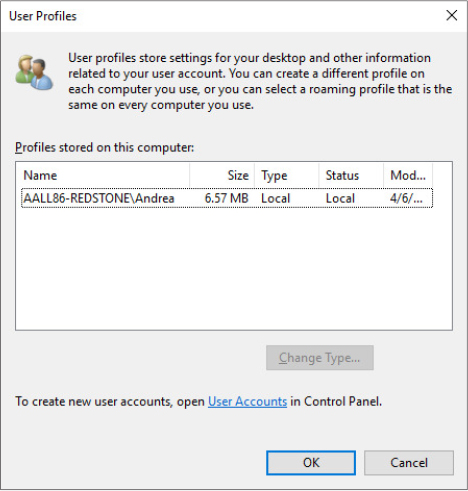
Figure 10-1 The User Profiles management dialog box.
HKEY_CLASSES_ROOT
HKCR consists of three types of information: file extension associations, COM class registrations, and the virtualized registry root for User Account Control (UAC). (See Chapter 7 of Part 1 for more information on UAC.) A key exists for every registered file name extension. Most keys contain a REG_SZ value that points to another key in HKCR containing the association information for the class of files that extension represents.
For example, HKCR.xls would point to information on Microsoft Office Excel files. For example, the default value contains “Excel.Sheet.8” that is used to instantiate the Excel COM object. Other keys contain configuration details for all COM objects registered on the system. The UAC virtualized registry is located in the VirtualStore key, which is not related to the other kinds of data stored in HKCR.
The data under HKEY_CLASSES_ROOT comes from two sources:
■ The per-user class registration data in HKCUSOFTWAREClasses (mapped to the file on hard disk Users<username>AppDataLocalMicrosoftWindowsUsrclass.dat)
■ Systemwide class registration data in HKLMSOFTWAREClasses
There is a separation of per-user registration data from systemwide registration data so that roaming profiles can contain customizations. Nonprivileged users and applications can read systemwide data and can add new keys and values to systemwide data (which are mirrored in their per-user data), but they can only modify existing keys and values in their private data. It also closes a security hole: a nonprivileged user cannot change or delete keys in the systemwide version HKEY_CLASSES_ROOT; thus, it cannot affect the operation of applications on the system.
HKEY_LOCAL_MACHINE
HKLM is the root key that contains all the systemwide configuration subkeys: BCD00000000, COMPONENTS (loaded dynamically as needed), HARDWARE, SAM, SECURITY, SOFTWARE, and SYSTEM.
The HKLMBCD00000000 subkey contains the Boot Configuration Database (BCD) information loaded as a registry hive. This database replaces the Boot.ini file that was used before Windows Vista and adds greater flexibility and isolation of per-installation boot configuration data. The BCD00000000 subkey is backed by the hidden BCD file, which, on UEFI systems, is located in EFIMicrosoftBoot. (For more information on the BCD, see Chapter 12, "Startup and shutdown”).
Each entry in the BCD, such as a Windows installation or the command-line settings for the installation, is stored in the Objects subkey, either as an object referenced by a GUID (in the case of a boot entry) or as a numeric subkey called an element. Most of these raw elements are documented in the BCD reference in Microsoft Docs and define various command-line settings or boot parameters. The value associated with each element subkey corresponds to the value for its respective command-line flag or boot parameter.
The BCDEdit command-line utility allows you to modify the BCD using symbolic names for the elements and objects. It also provides extensive help for all the boot options available. A registry hive can be opened remotely as well as imported from a hive file: you can modify or read the BCD of a remote computer by using the Registry Editor. The following experiment shows you how to enable kernel debugging by using the Registry Editor.
Open the Registry Editor and then navigate to the HKLMBCD00000000 key. Expand every subkey so that the numerical identifiers of each Elements key are fully visible.
Identify the boot entry for your Windows installation by locating the Description with a Type value of 0x10200003, and then select the 12000004 key in the Elements tree. In the Element value of that subkey, you should find the name of your version of Windows, such as Windows 10. In recent systems, you may have more than one Windows installation or various boot applications, like the Windows Recovery Environment or Windows Resume Application. In those cases, you may need to check the 22000002 Elements subkey, which contains the path, such as Windows.
Now that you’ve found the correct GUID for your Windows installation, create a new subkey under the Elements subkey for that GUID and name it 0x260000a0. If this subkey already exists, simply navigate to it. The found GUID should correspond to the identifier value under the Windows Boot Loader section shown by the bcdedit /v command (you can use the /store command-line option to inspect an offline store file).
If you had to create the subkey, now create a binary value called Element inside it.
Edit the value and set it to 1. This will enable kernel-mode debugging. Here’s what these changes should look like:

![]() Note
Note
The 0x12000004 ID corresponds to BcdLibraryString_ApplicationPath, whereas the 0x22000002 ID corresponds to BcdOSLoaderString_SystemRoot. Finally, the ID you added, 0x260000a0, corresponds to BcdOSLoaderBoolean_KernelDebuggerEnabled. These values are documented in the BCD reference in Microsoft Docs.
The HKLMCOMPONENTS subkey contains information pertinent to the Component Based Servicing (CBS) stack. This stack contains various files and resources that are part of a Windows installation image (used by the Automated Installation Kit or the OEM Preinstallation Kit) or an active installation. The CBS APIs that exist for servicing purposes use the information located in this key to identify installed components and their configuration information. This information is used whenever components are installed, updated, or removed either individually (called units) or in groups (called packages). To optimize system resources, because this key can get quite large, it is only dynamically loaded and unloaded as needed if the CBS stack is servicing a request. This key is backed by the COMPONENTS hive file located in Windowssystem32config.
The HKLMHARDWARE subkey maintains descriptions of the system’s legacy hardware and some hardware device-to-driver mappings. On a modern system, only a few peripherals—such as keyboard, mouse, and ACPI BIOS data—are likely to be found here. The Device Manager tool lets you view registry hardware information that it obtains by simply reading values out of the HARDWARE key (although it primarily uses the HKLMSYSTEMCurrentControlSetEnum tree).
HKLMSAM holds local account and group information, such as user passwords, group definitions, and domain associations. Windows Server systems operating as domain controllers store domain accounts and groups in Active Directory, a database that stores domainwide settings and information. (Active Directory isn’t described in this book.) By default, the security descriptor on the SAM key is configured so that even the administrator account doesn’t have access.
HKLMSECURITY stores systemwide security policies and user-rights assignments. HKLMSAM is linked into the SECURITY subkey under HKLMSECURITYSAM. By default, you can’t view the contents of HKLMSECURITY or HKLMSAM because the security settings of those keys allow access only by the System account. (System accounts are discussed in greater detail later in this chapter.) You can change the security descriptor to allow read access to administrators, or you can use PsExec to run Regedit in the local system account if you want to peer inside. However, that glimpse won’t be very revealing because the data is undocumented and the passwords are encrypted with one-way mapping—that is, you can’t determine a password from its encrypted form. The SAM and SECURITY subkeys are backed by the SAM and SECURITY hive files located in the Windowssystem32config path of the boot partition.
HKLMSOFTWARE is where Windows stores systemwide configuration information not needed to boot the system. Also, third-party applications store their systemwide settings here, such as paths to application files and directories and licensing and expiration date information.
HKLMSYSTEM contains the systemwide configuration information needed to boot the system, such as which device drivers to load and which services to start. The key is backed by the SYSTEM hive file located in Windowssystem32config. The Windows Loader uses registry services provided by the Boot Library for being able to read and navigate through the SYSTEM hive.
HKEY_CURRENT_CONFIG
HKEY_CURRENT_CONFIG is just a link to the current hardware profile, stored under HKLMSYSTEMCurrentControlSetHardware ProfilesCurrent. Hardware profiles are no longer supported in Windows, but the key still exists to support legacy applications that might depend on its presence.
HKEY_PERFORMANCE_DATA and HKEY_PERFORMANCE_TEXT
The registry is the mechanism used to access performance counter values on Windows, whether those are from operating system components or server applications. One of the side benefits of providing access to the performance counters via the registry is that remote performance monitoring works “for free” because the registry is easily accessible remotely through the normal registry APIs.
You can access the registry performance counter information directly by opening a special key named HKEY_PERFORMANCE_DATA and querying values beneath it. You won’t find this key by looking in the Registry Editor; this key is available only programmatically through the Windows registry functions, such as RegQueryValueEx. Performance information isn’t actually stored in the registry; the registry functions redirect access under this key to live performance information obtained from performance data providers.
The HKEY_PERFORMANCE_TEXT is another special key used to obtain performance counter information (usually name and description). You can obtain the name of any performance counter by querying data from the special Counter registry value. The Help special registry value yields all the counters description instead. The information returned by the special key are in US English. The HKEY_PERFORMANCE_NLSTEXT retrieves performance counters names and descriptions in the language in which the OS runs.
You can also access performance counter information by using the Performance Data Helper (PDH) functions available through the Performance Data Helper API (Pdh.dll). Figure 10-2 shows the components involved in accessing performance counter information.
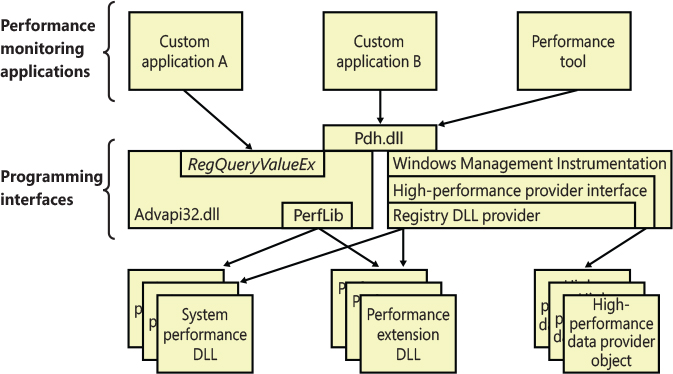
Figure 10-2 Registry performance counter architecture.
As shown in Figure 10-2, this registry key is abstracted by the Performance Library (Perflib), which is statically linked in Advapi32.dll. The Windows kernel has no knowledge about the HKEY_PERFORMANCE_DATA registry key, which explains why it is not shown in the Registry Editor.
Application hives
Applications are normally able to read and write data from the global registry. When an application opens a registry key, the Windows kernel performs an access check verification against the access token of its process (or thread in case the thread is impersonating; see Chapter 7 in Part 1 for more details) and the ACL that a particular key contains. An application is also able to load and save registry hives by using the RegSaveKeyEx and RegLoadKeyEx APIs. In those scenarios, the application operates on data that other processes running at a higher or same privilege level can interfere with. Furthermore, for loading and saving hives, the application needs to enable the Backup and Restore privileges. The two privileges are granted only to processes that run with an administrative account.
Clearly this was a limitation for most applications that want to access a private repository for storing their own settings. Windows 7 has introduced the concept of application hives. An application hive is a standard hive file (which is linked to the proper log files) that can be mounted visible only to the application that requested it. A developer can create a base hive file by using the RegSaveKeyEx API (which exports the content of a regular registry key in an hive file). The application can then mount the hive privately using the RegLoadAppKey function (specifying the REG_PROCESS_APPKEY flag prevents other applications from accessing the same hive). Internally, the function performs the following operations:
Creates a random GUID and assigns it to a private namespace, in the form of RegistryA<Random Guid>. (Registry forms the NT kernel registry namespace, described in the “The registry namespace and operation” section later in this chapter.)
Converts the DOS path of the specified hive file name in NT format and calls the NtLoadKeyEx native API with the proper set of parameters.
The NtLoadKeyEx function calls the regular registry callbacks. However, when it detects that the hive is an application hive, it uses CmLoadAppKey to load it (and its associated log files) in the private namespace, which is not enumerable by any other application and is tied to the lifetime of the calling process. (The hive and log files are still mapped in the “registry process,” though. The registry process will be described in the “Startup and registry process” section later in this chapter.) The application can use standard registry APIs to read and write its own private settings, which will be stored in the application hive. The hive will be automatically unloaded when the application exits or when the last handle to the key is closed.
Application hives are used by different Windows components, like the Application Compatibility telemetry agent (CompatTelRunner.exe) and the Modern Application Model. Universal Windows Platform (UWP) applications use application hives for storing information of WinRT classes that can be instantiated and are private for the application. The hive is stored in a file called ActivationStore.dat and is consumed primarily by the Activation Manager when an application is launched (or more precisely, is “activated”). The Background Infrastructure component of the Modern Application Model uses the data stored in the hive for storing background tasks information. In that way, when a background task timer elapses, it knows exactly in which application library the task’s code resides (and the activation type and threading model).
Furthermore, the modern application stack provides to UWP developers the concept of Application Data containers, which can be used for storing settings that can be local to the device in which the application runs (in this case, the data container is called local) or can be automatically shared between all the user’s devices that the application is installed on. Both kinds of containers are implemented in the Windows.Storage.ApplicationData.dll WinRT library, which uses an application hive, local to the application (the backing file is called settings.dat), to store the settings created by the UWP application.
Both the settings.dat and the ActivationStore.dat hive files are created by the Modern Application Model’s Deployment process (at app-installation time), which is covered extensively in Chapter 8, “System mechanisms,” (with a general discussion of packaged applications). The Application Data containers are documented at https://docs.microsoft.com/en-us/windows/uwp/get-started/settings-learning-track.
Transactional Registry (TxR)
Thanks to the Kernel Transaction Manager (KTM; for more information see the section about the KTM in Chapter 8), developers have access to a straightforward API that allows them to implement robust error-recovery capabilities when performing registry operations, which can be linked with nonregistry operations, such as file or database operations.
Three APIs support transactional modification of the registry: RegCreateKeyTransacted, RegOpenKeyTransacted, and RegDeleteKeyTransacted. These new routines take the same parameters as their nontransacted analogs except that a new transaction handle parameter is added. A developer supplies this handle after calling the KTM function CreateTransaction.
After a transacted create or open operation, all subsequent registry operations—such as creating, deleting, or modifying values inside the key—will also be transacted. However, operations on the subkeys of a transacted key will not be automatically transacted, which is why the third API, RegDeleteKeyTransacted exists. It allows the transacted deletion of subkeys, which RegDeleteKeyEx would not normally do.
Data for these transacted operations is written to log files using the common logging file system (CLFS) services, similar to other KTM operations. Until the transaction is committed or rolled back (both of which might happen programmatically or as a result of a power failure or system crash, depending on the state of the transaction), the keys, values, and other registry modifications performed with the transaction handle will not be visible to external applications through the nontransacted APIs. Also, transactions are isolated from each other; modifications made inside one transaction will not be visible from inside other transactions or outside the transaction until the transaction is committed.
![]() Note
Note
A nontransactional writer will abort a transaction in case of conflict—for example, if a value was created inside a transaction and later, while the transaction is still active, a nontransactional writer tries to create a value under the same key. The nontransactional operation will succeed, and all operations in the conflicting transaction will be aborted.
The isolation level (the “I” in ACID) implemented by TxR resource managers is read-commit, which means that changes become available to other readers (transacted or not) immediately after being committed. This mechanism is important for people who are familiar with transactions in databases, where the isolation level is predictable-reads (or cursor-stability, as it is called in database literature). With a predictable-reads isolation level, after you read a value inside a transaction, subsequent reads returns the same data. Read-commit does not make this guarantee. One of the consequences is that registry transactions can’t be used for “atomic” increment/decrement operations on a registry value.
To make permanent changes to the registry, the application that has been using the transaction handle must call the KTM function CommitTransaction. (If the application decides to undo the changes, such as during a failure path, it can call the RollbackTransaction API.) The changes are then visible through the regular registry APIs as well.
![]() Note
Note
If a transaction handle created with CreateTransaction is closed before the transaction is committed (and there are no other handles open to that transaction), the system rolls back that transaction.
Apart from using the CLFS support provided by the KTM, TxR also stores its own internal log files in the %SystemRoot%System32ConfigTxr folder on the system volume; these files have a .regtrans-ms extension and are hidden by default. There is a global registry resource manager (RM) that services all the hives mounted at boot time. For every hive that is mounted explicitly, an RM is created. For applications that use registry transactions, the creation of an RM is transparent because KTM ensures that all RMs taking part in the same transaction are coordinated in the two-phase commit/abort protocol. For the global registry RM, the CLFS log files are stored, as mentioned earlier, inside System32ConfigTxr. For other hives, they are stored alongside the hive (in the same directory). They are hidden and follow the same naming convention, ending in .regtrans-ms. The log file names are prefixed with the name of the hive to which they correspond.
Monitoring registry activity
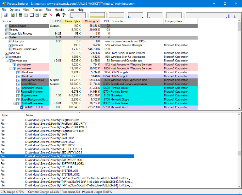
Because the system and applications depend so heavily on configuration settings to guide their behavior, system and application failures can result from changing registry data or security. When the system or an application fails to read settings that it assumes it will always be able to access, it might not function properly, display error messages that hide the root cause, or even crash. It’s virtually impossible to know what registry keys or values are misconfigured without understanding how the system or the application that’s failing is accessing the registry. In such situations, the Process Monitor utility from Windows Sysinternals (https://docs.microsoft.com/en-us/sysinternals/) might provide the answer.
Process Monitor lets you monitor registry activity as it occurs. For each registry access, Process Monitor shows you the process that performed the access; the time, type, and result of the access; and the stack of the thread at the moment of the access. This information is useful for seeing how applications and the system rely on the registry, discovering where applications and the system store configuration settings, and troubleshooting problems related to applications having missing registry keys or values. Process Monitor includes advanced filtering and highlighting so that you can zoom in on activity related to specific keys or values or to the activity of particular processes.
Process Monitor internals
Process Monitor relies on a device driver that it extracts from its executable image at runtime before starting it. Its first execution requires that the account running it has the Load Driver privilege as well as the Debug privilege; subsequent executions in the same boot session require only the Debug privilege because, once loaded, the driver remains resident.
Have Notepad save a setting you can easily search for in a Process Monitor trace. You can do this by running Notepad, setting the font to Times New Roman, and then exiting Notepad.
Run Process Monitor. Open the filter dialog box and the Process Name filter, and type notepad.exe as the string to match. Confirm by clicking the Add button. This step specifies that Process Monitor will log only activity by the notepad.exe process.
Run Notepad again, and after it has launched, stop Process Monitor’s event capture by toggling Capture Events on the Process Monitor File menu.
Scroll to the top line of the resultant log and select it.
Press Ctrl+F to open a Find dialog box, and search for times new. Process Monitor should highlight a line like the one shown in the following screen that represents Notepad reading the font value from the registry. Other operations in the immediate vicinity should relate to other Notepad settings.
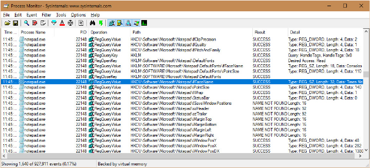
Right-click the highlighted line and click Jump To. Process Monitor starts Regedit (if it’s not already running) and causes it to navigate to and select the Notepad-referenced registry value.
Registry internals
This section describes how the configuration manager—the executive subsystem that implements the registry—organizes the registry’s on-disk files. We’ll examine how the configuration manager manages the registry as applications and other operating system components read and change registry keys and values. We’ll also discuss the mechanisms by which the configuration manager tries to ensure that the registry is always in a recoverable state, even if the system crashes while the registry is being modified.
Hives
On disk, the registry isn’t simply one large file but rather a set of discrete files called hives. Each hive contains a registry tree, which has a key that serves as the root or starting point of the tree. Subkeys and their values reside beneath the root. You might think that the root keys displayed by the Registry Editor correlate to the root keys in the hives, but such is not the case. Table 10-5 lists registry hives and their on-disk file names. The path names of all hives except for user profiles are coded into the configuration manager. As the configuration manager loads hives, including system profiles, it notes each hive’s path in the values under the HKLMSYSTEMCurrentControlSetControlHivelist subkey, removing the path if the hive is unloaded. It creates the root keys, linking these hives together to build the registry structure you’re familiar with and that the Registry Editor displays.
Table 10-5 On-disk files corresponding to paths in the registry
Hive Registry Path |
Hive File Path |
|---|---|
HKEY_LOCAL_MACHINEBCD00000000 |
EFIMicrosoftBoot |
HKEY_LOCAL_MACHINECOMPONENTS |
%SystemRoot%System32ConfigComponents |
HKEY_LOCAL_MACHINESYSTEM |
%SystemRoot%System32ConfigSystem |
HKEY_LOCAL_MACHINESAM |
%SystemRoot%System32ConfigSam |
HKEY_LOCAL_MACHINESECURITY |
%SystemRoot%System32ConfigSecurity |
HKEY_LOCAL_MACHINESOFTWARE |
%SystemRoot%System32ConfigSoftware |
HKEY_LOCAL_MACHINEHARDWARE |
Volatile hive |
HKEY_LOCAL_MACHINEWindowsAppLockerCache |
%SystemRoot%System32AppLockerAppCache.dat |
HKEY_LOCAL_MACHINEELAM |
%SystemRoot%System32ConfigElam |
HKEY_USERS<SID of local service account> |
%SystemRoot%ServiceProfilesLocalServiceNtuser.dat |
HKEY_USERS<SID of network service account> |
%SystemRoot%ServiceProfilesNetworkServiceNtUser.dat |
HKEY_USERS<SID of username> |
Users<username>Ntuser.dat |
HKEY_USERS<SID of username>_Classes |
Users<username>AppDataLocalMicrosoftWindowsUsrclass.dat |
HKEY_USERS.DEFAULT |
%SystemRoot%System32ConfigDefault |
Virtualized HKEY_LOCAL_MACHINESOFTWARE |
Different paths. Usually ProgramDataPackages<PackageFullName><UserSid>SystemAppDataHeliumCache<RandomName>.dat for Centennial |
Virtualized HKEY_CURRENT_USER |
Different paths. Usually ProgramDataPackages<PackageFullName><UserSid>SystemAppDataHeliumUser.dat for Centennial |
Virtualized HKEY_LOCAL_MACHINESOFTWAREClasses |
Different paths. Usually ProgramDataPackages<PackageFullName><UserSid>SystemAppDataHeliumUserClasses.dat for Centennial |
You’ll notice that some of the hives listed in Table 10-5 are volatile and don’t have associated files. The system creates and manages these hives entirely in memory; the hives are therefore temporary. The system creates volatile hives every time it boots. An example of a volatile hive is the HKLMHARDWARE hive, which stores information about physical devices and the devices’ assigned resources. Resource assignment and hardware detection occur every time the system boots, so not storing this data on disk is logical. You will also notice that the last three entries in the table represent virtualized hives. Starting from Windows 10 Anniversary Update, the NT kernel supports the Virtualized Registry (VReg), with the goal to provide support for Centennial packaged applications, which runs in a Helium container. Every time the user runs a centennial application (like the modern Skype, for example), the system mounts the needed package hives. Centennial applications and the Modern Application Model have been extensively discussed in Chapter 8.
Hive size limits
In some cases, hive sizes are limited. For example, Windows places a limit on the size of the HKLMSYSTEM hive. It does so because Winload reads the entire HKLMSYSTEM hive into physical memory near the start of the boot process when virtual memory paging is not enabled. Winload also loads Ntoskrnl and boot device drivers into physical memory, so it must constrain the amount of physical memory assigned to HKLMSYSTEM. (See Chapter 12 for more information on the role Winload plays during the startup process.) On 32-bit systems, Winload allows the hive to be as large as 400 MB or half the amount of physical memory on the system, whichever is lower. On x64 systems, the lower bound is 2 GB.
Startup and the registry process
Before Windows 8.1, the NT kernel was using paged pool for storing the content of every loaded hive file. Most of the hives loaded in the system remained in memory until the system shutdown (a good example is the SOFTWARE hive, which is loaded by the Session Manager after phase 1 of the System startup is completed and sometimes could be multiple hundreds of megabytes in size). Paged pool memory could be paged out by the balance set manager of the memory manager, if it is not accessed for a certain amount of time (see Chapter 5, “Memory management,” in Part 1 for more details). This implies that unused parts of a hive do not remain in the working set for a long time. Committed virtual memory is backed by the page file and requires the system Commit charge to be increased, reducing the total amount of virtual memory available for other purposes.
To overcome this problem, Windows 10 April 2018 Update (RS4) introduced support for the section-backed registry. At phase 1 of the NT kernel initialization, the Configuration manager startup routine initializes multiple components of the Registry: cache, worker threads, transactions, callbacks support, and so on. It then creates the Key object type, and, before loading the needed hives, it creates the Registry process. The Registry process is a fully-protected (same protection as the SYSTEM process: WinSystem level), minimal process, which the configuration manager uses for performing most of the I/Os on opened registry hives. At initialization time, the configuration manager maps the preloaded hives in the Registry process. The preloaded hives (SYSTEM and ELAM) continue to reside in nonpaged memory, though (which is mapped using kernel addresses). Later in the boot process, the Session Manager loads the Software hive by invoking the NtInitializeRegistry system call.
A section object backed by the “SOFTWARE” hive file is created: the configuration manager divides the file in 2-MB chunks and creates a reserved mapping in the Registry process’s user-mode address space for each of them (using the NtMapViewOfSection native API. Reserved mappings are tracked by valid VADs, but no actual pages are allocated. See Chapter 5 in Part 1 for further details). Each 2-MB view is read-only protected. When the configuration manager wants to read some data from the hive, it accesses the view’s pages and produces an access fault, which causes the shared pages to be brought into memory by the memory manager. At that time, the system working set charge is increased, but not the commit charge (the pages are backed by the hive file itself, and not by the page file).
At initialization time, the configuration manager sets the hard-working set limit to the Registry process at 64 MB. This means that in high memory pressure scenarios, it is guaranteed that no more than 64 MB of working set is consumed by the registry. Every time an application or the system uses the APIs to access the registry, the configuration manager attaches to the Registry process address space, performs the needed work, and returns the results. The configuration manager doesn’t always need to switch address spaces: when the application wants to access a registry key that is already in the cache (a Key control block already exists), the configuration manager skips the process attach and returns the cached data. The registry process is primarily used for doing I/O on the low-level hive file.
When the system writes or modifies registry keys and values stored in a hive, it performs a copy-on-write operation (by first changing the memory protection of the 2 MB view to PAGE_WRITECOPY). Writing to memory marked as copy-on-write creates new private pages and increases the system commit charge. When a registry update is requested, the system immediately writes new entries in the hive’s log, but the writing of the actual pages belonging to the primary hive file is deferred. Dirty hive’s pages, as for every normal memory page, can be paged out to disk. Those pages are written to the primary hive file when the hive is being unloaded or by the Reconciler: one of the configuration manager’s lazy writer threads that runs by default once every hour (the time period is configurable by setting the HKLMSYSTEM CurrentControlSetControlSession ManagerConfiguration ManagerRegistryLazyReconcileInterval registry value).
The Reconciler and the Incremental logging are discussed in the “Incremental logging” section later in this chapter.
Registry symbolic links
A special type of key known as a registry symbolic link makes it possible for the configuration manager to link keys to organize the registry. A symbolic link is a key that redirects the configuration manager to another key. Thus, the key HKLMSAM is a symbolic link to the key at the root of the SAM hive. Symbolic links are created by specifying the REG_CREATE_LINK parameter to RegCreateKey or RegCreateKeyEx. Internally, the configuration manager will create a REG_LINK value called SymbolicLinkValue, which contains the path to the target key. Because this value is a REG_LINK instead of a REG_SZ, it will not be visible with Regedit—it is, however, part of the on-disk registry hive.
Hive structure
The configuration manager logically divides a hive into allocation units called blocks in much the same way that a file system divides a disk into clusters. By definition, the registry block size is 4096 bytes (4 KB). When new data expands a hive, the hive always expands in block-granular increments. The first block of a hive is the base block.
The base block includes global information about the hive, including a signature—regf—that identifies the file as a hive, two updated sequence numbers, a time stamp that shows the last time a write operation was initiated on the hive, information on registry repair or recovery performed by Winload, the hive format version number, a checksum, and the hive file’s internal file name (for example, DeviceHarddiskVolume1WINDOWSSYSTEM32CONFIGSAM). We’ll clarify the significance of the two updated sequence numbers and time stamp when we describe how data is written to a hive file.
The hive format version number specifies the data format within the hive. The configuration manager uses hive format version 1.5, which supports large values (values larger than 1 MB are supported) and improved searching (instead of caching the first four characters of a name, a hash of the entire name is used to reduce collisions). Furthermore, the configuration manager supports differencing hives introduced for container support. Differencing hives uses hive format 1.6.
Windows organizes the registry data that a hive stores in containers called cells. A cell can hold a key, a value, a security descriptor, a list of subkeys, or a list of key values. A four-byte character tag at the beginning of a cell’s data describes the data’s type as a signature. Table 10-6 describes each cell data type in detail. A cell’s header is a field that specifies the cell’s size as the 1’s complement (not present in the CM_ structures). When a cell joins a hive and the hive must expand to contain the cell, the system creates an allocation unit called a bin.
Table 10-6 Cell data types
Data Type |
Structure Type |
Description |
|---|---|---|
Key cell |
CM_KEY_NODE |
A cell that contains a registry key, also called a key node. A key cell contains a signature (kn for a key, kl for a link node), the time stamp of the most recent update to the key, the cell index of the key’s parent key cell, the cell index of the subkey-list cell that identifies the key’s subkeys, a cell index for the key’s security descriptor cell, a cell index for a string key that specifies the class name of the key, and the name of the key (for example, CurrentControlSet). It also saves cached information such as the number of subkeys under the key, as well as the size of the largest key, value name, value data, and class name of the subkeys under this key. |
Value cell |
CM_KEY_VALUE |
A cell that contains information about a key’s value. This cell includes a signature (kv), the value’s type (for example, REG_ DWORD or REG_BINARY), and the value’s name (for example, Boot-Execute). A value cell also contains the cell index of the cell that contains the value’s data. |
Big Value cell |
CM_BIG_DATA |
A cell that represents a registry value bigger than 16 kB. For this kind of cell type, the cell content is an array of cell indexes each pointing to a 16-kB cell, which contains a chunk of the registry value. |
Subkey-list cell |
CM_KEY_INDEX |
A cell composed of a list of cell indexes for key cells that are all subkeys of a common parent key. |
Value-list cell |
CM_KEY_INDEX |
A cell composed of a list of cell indexes for value cells that are all values of a common parent key. |
Security-descriptor cell |
CM_KEY_SECURITY |
A cell that contains a security descriptor. Security-descriptor cells include a signature (ks) at the head of the cell and a reference count that records the number of key nodes that share the security descriptor. Multiple key cells can share security-descriptor cells. |
A bin is the size of the new cell rounded up to the next block or page boundary, whichever is higher. The system considers any space between the end of the cell and the end of the bin to be free space that it can allocate to other cells. Bins also have headers that contain a signature, hbin, and a field that records the offset into the hive file of the bin and the bin’s size.
By using bins instead of cells, to track active parts of the registry, Windows minimizes some management chores. For example, the system usually allocates and deallocates bins less frequently than it does cells, which lets the configuration manager manage memory more efficiently. When the configuration manager reads a registry hive into memory, it reads the whole hive, including empty bins, but it can choose to discard them later. When the system adds and deletes cells in a hive, the hive can contain empty bins interspersed with active bins. This situation is similar to disk fragmentation, which occurs when the system creates and deletes files on the disk. When a bin becomes empty, the configuration manager joins to the empty bin any adjacent empty bins to form as large a contiguous empty bin as possible. The configuration manager also joins adjacent deleted cells to form larger free cells. (The configuration manager shrinks a hive only when bins at the end of the hive become free. You can compact the registry by backing it up and restoring it using the Windows RegSaveKey and RegReplaceKey functions, which are used by the Windows Backup utility. Furthermore, the system compacts the bins at hive initialization time using the Reorganization algorithm, as described later.)
The links that create the structure of a hive are called cell indexes. A cell index is the offset of a cell into the hive file minus the size of the base block. Thus, a cell index is like a pointer from one cell to another cell that the configuration manager interprets relative to the start of a hive. For example, as you saw in Table 10-6, a cell that describes a key contains a field specifying the cell index of its parent key; a cell index for a subkey specifies the cell that describes the subkeys that are subordinate to the specified subkey. A subkey-list cell contains a list of cell indexes that refer to the subkey’s key cells. Therefore, if you want to locate, for example, the key cell of subkey A whose parent is key B, you must first locate the cell containing key B’s subkey list using the subkey-list cell index in key B’s cell. Then you locate each of key B’s subkey cells by using the list of cell indexes in the subkey-list cell. For each subkey cell, you check to see whether the subkey’s name, which a key cell stores, matches the one you want to locate—in this case, subkey A.
The distinction between cells, bins, and blocks can be confusing, so let’s look at an example of a simple registry hive layout to help clarify the differences. The sample registry hive file in Figure 10-3 contains a base block and two bins. The first bin is empty, and the second bin contains several cells. Logically, the hive has only two keys: the root key Root and a subkey of Root, Sub Key. Root has two values, Val 1 and Val 2. A subkey-list cell locates the root key’s subkey, and a value-list cell locates the root key’s values. The free spaces in the second bin are empty cells. Figure 10-3 doesn’t show the security cells for the two keys, which would be present in a hive.
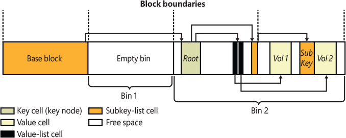
Figure 10-3 Internal structure of a registry hive.
To optimize searches for both values and subkeys, the configuration manager sorts subkey-list cells alphabetically. The configuration manager can then perform a binary search when it looks for a subkey within a list of subkeys. The configuration manager examines the subkey in the middle of the list, and if the name of the subkey the configuration manager is looking for alphabetically precedes the name of the middle subkey, the configuration manager knows that the subkey is in the first half of the subkey list; otherwise, the subkey is in the second half of the subkey list. This splitting process continues until the configuration manager locates the subkey or finds no match. Value-list cells aren’t sorted, however, so new values are always added to the end of the list.
Cell maps
If hives never grew, the configuration manager could perform all its registry management on the in-memory version of a hive as if the hive were a file. Given a cell index, the configuration manager could calculate the location in memory of a cell simply by adding the cell index, which is a hive file offset, to the base of the in-memory hive image. Early in the system boot, this process is exactly what Winload does with the SYSTEM hive: Winload reads the entire SYSTEM hive into memory as a read-only hive and adds the cell indexes to the base of the in-memory hive image to locate cells. Unfortunately, hives grow as they take on new keys and values, which means the system must allocate new reserved views and extend the hive file to store the new bins that contain added keys and values. The reserved views that keep the registry data in memory aren’t necessarily contiguous.
To deal with noncontiguous memory addresses referencing hive data in memory, the configuration manager adopts a strategy similar to what the Windows memory manager uses to map virtual memory addresses to physical memory addresses. While a cell index is only an offset in the hive file, the configuration manager employs a two-level scheme, which Figure 10-4 illustrates, when it represents the hive using the mapped views in the registry process. The scheme takes as input a cell index (that is, a hive file offset) and returns as output both the address in memory of the block the cell index resides in and the address in memory of the block the cell resides in. Remember that a bin can contain one or more blocks and that hives grow in bins, so Windows always represents a bin with a contiguous region of memory. Therefore, all blocks within a bin occur within the same 2-MB hive’s mapped view.

Figure 10-4 Structure of a cell index.
To implement the mapping, the configuration manager divides a cell index logically into fields, in the same way that the memory manager divides a virtual address into fields. Windows interprets a cell index’s first field as an index into a hive’s cell map directory. The cell map directory contains 1024 entries, each of which refers to a cell map table that contains 512 map entries. An entry in this cell map table is specified by the second field in the cell index. That entry locates the bin and block memory addresses of the cell.
In the final step of the translation process, the configuration manager interprets the last field of the cell index as an offset into the identified block to precisely locate a cell in memory. When a hive initializes, the configuration manager dynamically creates the mapping tables, designating a map entry for each block in the hive, and it adds and deletes tables from the cell directory as the changing size of the hive requires.
Hive reorganization
As for real file systems, registry hives suffer fragmentation problems: when cells in the bin are freed and it is not possible to coalescence them in a contiguous manner, fragmented little chunks of free space are created into various bins. If there is not enough available contiguous space for new cells, new bins are appended at the end of the hive file, while the fragmented ones will be rarely repurposed. To overcome this problem, starting from Windows 8.1, every time the configuration manager mounts a hive file, it checks whether a hive’s reorganization needs to be performed. The configuration manager records the time of the last reorganization in the hive’s basic block. If the hive has valid log files, is not volatile, and if the time passed after the previous reorganization is greater than seven days, the reorganization operation is started. The reorganization is an operation that has two main goals: shrink the hive file and optimize it. It starts by creating a new empty hive that is identical to the original one but does not contains any cells in it. The created clone is used to copy the root key of the original hive, with all its values (but no subkeys). A complex algorithm analyzes all the child keys: indeed, during its normal activity, the configuration manager records whether a particular key is accessed, and, if so, stores an index representing the current runtime phase of the operating system (Boot or normal) in its key cell.
The reorganization algorithm first copies the keys accessed during the normal execution of the OS, then the ones accessed during the boot phase, and finally the keys that have not been accessed at all (since the last reorganization). This operation groups all the different keys in contiguous bins of the hive file. The copy operation, by definition, produces a nonfragmented hive file (each cell is stored sequentially in the bin, and new bin are always appended at the end of the file). Furthermore, the new hive has the characteristic to contain hot and cold classes of keys stored in big contiguous chunks. This result renders the boot and runtime phase of the operating system much quicker when reading data from the registry.
The reorganization algorithm resets the access state of all the new copied cells. In this way, the system can track the hive’s keys usage by restarting from a neutral state. The new usage statistics will be consumed by the next reorganization, which will start after seven days. The configuration manager stores the results of a reorganization cycle in the HKLMSYSTEMCurrentControlSetControlSession ManagerConfiguration ManagerDefrag registry key, as shown in Figure 10-5. In the sample screenshot, the last reorganization was run on April 10, 2019 and saved 10 MB of fragmented hive space.

Figure 10-5 Registry reorganization data.
The registry namespace and operation
The configuration manager defines a key object type to integrate the registry’s namespace with the kernel’s general namespace. The configuration manager inserts a key object named Registry into the root of the Windows namespace, which serves as the entry point to the registry. Regedit shows key names in the form HKEY_LOCAL_MACHINESYSTEMCurrentControlSet, but the Windows subsystem translates such names into their object namespace form (for example, RegistryMachineSystemCurrentControlSet). When the Windows object manager parses this name, it encounters the key object by the name of Registry first and hands the rest of the name to the configuration manager. The configuration manager takes over the name parsing, looking through its internal hive tree to find the desired key or value. Before we describe the flow of control for a typical registry operation, we need to discuss key objects and key control blocks. Whenever an application opens or creates a registry key, the object manager gives a handle with which to reference the key to the application. The handle corresponds to a key object that the configuration manager allocates with the help of the object manager. By using the object manager’s object support, the configuration manager takes advantage of the security and reference-counting functionality that the object manager provides.
For each open registry key, the configuration manager also allocates a key control block. A key control block stores the name of the key, includes the cell index of the key node that the control block refers to, and contains a flag that notes whether the configuration manager needs to delete the key cell that the key control block refers to when the last handle for the key closes. Windows places all key control blocks into a hash table to enable quick searches for existing key control blocks by name. A key object points to its corresponding key control block, so if two applications open the same registry key, each receives a key object, and both key objects point to a common key control block.
When an application opens an existing registry key, the flow of control starts with the application specifying the name of the key in a registry API that invokes the object manager’s name-parsing routine. The object manager, upon encountering the configuration manager’s registry key object in the namespace, hands the path name to the configuration manager. The configuration manager performs a lookup on the key control block hash table. If the related key control block is found there, there’s no need for any further work (no registry process attach is needed); otherwise, the lookup provides the configuration manager with the closest key control block to the searched key, and the lookup continues by attaching to the registry process and using the in-memory hive data structures to search through keys and subkeys to find the specified key. If the configuration manager finds the key cell, the configuration manager searches the key control block tree to determine whether the key is open (by the same application or another one). The search routine is optimized to always start from the closest ancestor with a key control block already opened. For example, if an application opens RegistryMachineKey1Subkey2, and RegistryMachine is already open, the parse routine uses the key control block of RegistryMachine as a starting point. If the key is open, the configuration manager increments the existing key control block’s reference count. If the key isn’t open, the configuration manager allocates a new key control block and inserts it into the tree. Then the configuration manager allocates a key object, points the key object at the key control block, detaches from the Registry process, and returns control to the object manager, which returns a handle to the application.
When an application creates a new registry key, the configuration manager first finds the key cell for the new key’s parent. The configuration manager then searches the list of free cells for the hive in which the new key will reside to determine whether cells exist that are large enough to hold the new key cell. If there aren’t any free cells large enough, the configuration manager allocates a new bin and uses it for the cell, placing any space at the end of the bin on the free cell list. The new key cell fills with pertinent information—including the key’s name—and the configuration manager adds the key cell to the subkey list of the parent key’s subkey-list cell. Finally, the system stores the cell index of the parent cell in the new subkey’s key cell.
The configuration manager uses a key control block’s reference count to determine when to delete the key control block. When all the handles that refer to a key in a key control block close, the reference count becomes 0, which denotes that the key control block is no longer necessary. If an application that calls an API to delete the key sets the delete flag, the configuration manager can delete the associated key from the key’s hive because it knows that no application is keeping the key open.
Stable storage
To make sure that a nonvolatile registry hive (one with an on-disk file) is always in a recoverable state, the configuration manager uses log hives. Each nonvolatile hive has an associated log hive, which is a hidden file with the same base name as the hive and a logN extension. To ensure forward progress, the configuration manager uses a dual-logging scheme. There are potentially two log files: .log1 and .log2. If, for any reason, .log1 was written but a failure occurred while writing dirty data to the primary log file, the next time a flush happens, a switch to .log2 occurs with the cumulative dirty data. If that fails as well, the cumulative dirty data (the data in .log1 and the data that was dirtied in between) is saved in .log2. As a consequence, .log1 will be used again next time around, until a successful write operation is done to the primary log file. If no failure occurs, only .log1 is used.
For example, if you look in your %SystemRoot%System32Config directory (and you have the Show Hidden Files And Folders folder option selected and Hide Protected Operating System Files unselected; otherwise, you won’t see any file), you’ll see System.log1, Sam.log1, and other .log1 and .log2 files. When a hive initializes, the configuration manager allocates a bit array in which each bit represents a 512-byte portion, or sector, of the hive. This array is called the dirty sector array because a bit set in the array means that the system has modified the corresponding sector in the hive in memory and must write the sector back to the hive file. (A bit not set means that the corresponding sector is up to date with the in-memory hive’s contents.)
When the creation of a new key or value or the modification of an existing key or value takes place, the configuration manager notes the sectors of the primary hive that change and writes them in the hive’s dirty sectors array in memory. Then the configuration manager schedules a lazy flush operation, or a log sync. The hive lazy writer system thread wakes up one minute after the request to synchronize the hive’s log. It generates new log entries from the in-memory hive sectors referenced by valid bits of the dirty sectors array and writes them to the hive log files on disk. At the same time, the system flushes all the registry modifications that take place between the time a hive sync is requested and the time the hive sync occurs. The lazy writer uses low priority I/Os and writes dirty sectors to the log file on disk (and not to the primary hive). When a hive sync takes place, the next hive sync occurs no sooner than one minute later.
If the lazy writer simply wrote all a hive’s dirty sectors to the hive file and the system crashed in mid-operation, the hive file would be in an inconsistent (corrupted) and unrecoverable state. To prevent such an occurrence, the lazy writer first dumps the hive’s dirty sector array and all the dirty sectors to the hive’s log file, increasing the log file’s size if necessary. A hive’s basic block contains two sequence numbers. After the first flush operation (and not in the subsequent flushes), the configuration manager updates one of the sequence number, which become bigger than the second one. Thus, if the system crashes during the write operations to the hive, at the next reboot the configuration manager notices that the two sequence numbers in the hive’s base block don’t match. The configuration manager can update the hive with the dirty sectors in the hive’s log file to roll the hive forward. The hive is then up to date and consistent.
After writing log entries in the hive’s log, the lazy flusher clears the corresponding valid bits in the dirty sector array but inserts those bits in another important vector: the unreconciled array. The latter is used by the configuration manager to understand which log entries to write in the primary hive. Thanks to the new incremental logging support (discussed later), the primary hive file is rarely written during the runtime execution of the operating system. The hive’s sync protocol (not to be confused by the log sync) is the algorithm used to write all the in-memory and in-log registry’s modifications to the primary hive file and to set the two sequence numbers in the hive. It is indeed an expensive multistage operation that is described later.
The Reconciler, which is another type of lazy writer system thread, wakes up once every hour, freezes up the log, and writes all the dirty log entries in the primary hive file. The reconciliation algorithm knows which parts of the in-memory hive to write to the primary file thanks to both the dirty sectors and unreconciled array. Reconciliation happens rarely, though. If a system crashes, the configuration manager has all the information needed to reconstruct a hive, thanks to the log entries that have been already written in the log files. Performing registry reconciliation only once per hour (or when the size of the log is behind a threshold, which depends on the size of the volume in which the hive reside) is a big performance improvement. The only possible time window in which some data loss could happen in the hive is between log flushes.
Note that the Reconciliation still does not update the second sequence number in the main hive file. The two sequence numbers will be updated with an equal value only in the “validation” phase (another form of hive flushing), which happens only at the hive’s unload time (when an application calls the RegUnloadKey API), when the system shuts down, or when the hive is first loaded. This means that in most of the lifetime of the operating system, the main registry hive is in a dirty state and needs its log file to be correctly read.
The Windows Boot Loader also contains some code related to registry reliability. For example, it can parse the System.log file before the kernel is loaded and do repairs to fix consistency. Additionally, in certain cases of hive corruption (such as if a base block, bin, or cell contains data that fails consistency checks), the configuration manager can reinitialize corrupted data structures, possibly deleting subkeys in the process, and continue normal operation. If it must resort to a self-healing operation, it pops up a system error dialog box notifying the user.
Incremental logging
As mentioned in the previous section, Windows 8.1 introduced a big improvement on the performance of the hive sync algorithm thanks to incremental logging. Normally, cells in a hive file can be in four different states:
■ Clean The cell’s data is in the hive’s primary file and has not been modified.
■ Dirty The cell’s data has been modified but resides only in memory.
■ Unreconciled The cell’s data has been modified and correctly written to a log file but isn’t in the primary file yet.
■ Dirty and Unreconciled After the cell has been written to the log file, it has been modified again. Only the first modification is on the log file, whereas the last one resides in memory only.
The original pre-Windows 8.1 synchronization algorithm was executing five seconds after one or more cells were modified. The algorithm can be summarized in four steps:
The configuration manager writes all the modified cells signaled by the dirty vector in a single entry in the log file.
It invalidates the hive’s base block (by setting only one sequence number with an incremented value than the other one).
It writes all the modified data on the primary hive’s file.
It performs the validation of the primary hive (the validation sets the two sequence numbers with an identical value in the primary hive file).
To maintain the integrity and the recoverability of the hive, the algorithm should emit a flush operation to the file system driver after each phase; otherwise, corruption could happen. Flush operations on random access data can be very expensive (especially on standard rotation disks).
Incremental logging solved the performance problem. In the legacy algorithm, one single log entry was written containing all the dirty data between multiple hive validations; the incremental model broke this assumption. The new synchronization algorithm writes a single log entry every time the lazy flusher executes, which, as discussed previously, invalidates the primary hive’s base block only in the first time it executes. Subsequent flushes continue to write new log entries without touching the hive’s primary file. Every hour, or if the space in the log exhausts, the Reconciler writes all the data stored in the log entries to the primary hive’s file without performing the validation phase. In this way, space in the log file is reclaimed while maintaining the recoverability of the hive. If the system crashes at this stage, the log contains original entries that will be reapplied at hive loading time; otherwise, new entries are reapplied at the beginning of the log, and, in case the system crashes later, at hive load time only the new entries in the log are applied.
Figure 10-6 shows the possible crash situations and how they are managed by the incremental logging scheme. In case A, the system has written new data to the hive in memory, and the lazy flusher has written the corresponding entries in the log (but no reconciliation happened). When the system restarts, the recovery procedure applies all the log entries to the primary hive and validates the hive file again. In case B, the reconciler has already written the data stored in the log entries to the primary hive before the crash (no hive validation happened). At system reboot, the recovery procedure reapplies the existing log entries, but no modification in the primary hive file are made. Case C shows a similar situation of case B but where a new entry has been written to the log after the reconciliation. In this case, the recovery procedure writes only the last modification that is not in the primary file.
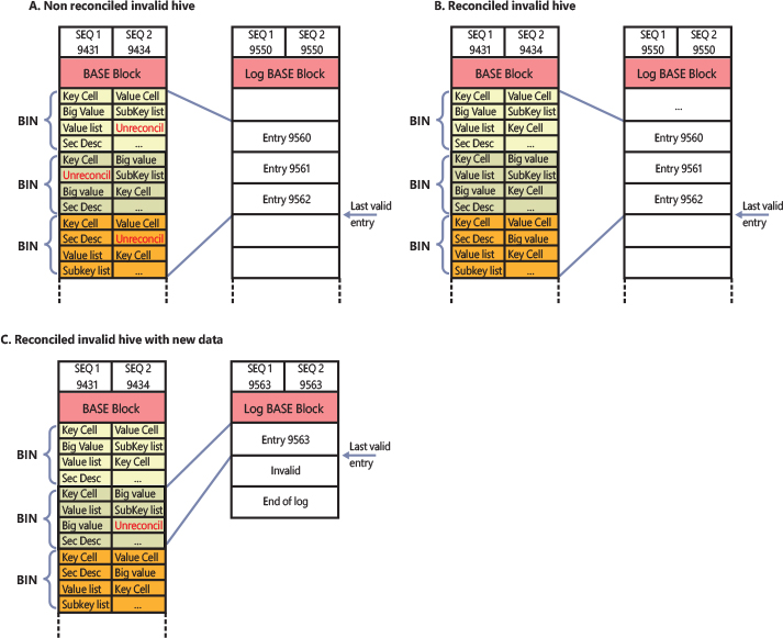
Figure 10-6 Consequences of possible system crashes in different times.
The hive’s validation is performed only in certain (rare) cases. When a hive is unloaded, the system performs reconciliation and then validates the hive’s primary file. At the end of the validation, it sets the two sequence numbers of the hive’s primary file to a new identical value and emits the last file system flush request before unloading the hive from memory. When the system restarts, the hive load’s code detects that the hive primary is in a clean state (thanks to the two sequence numbers having the same value) and does not start any form of the hive’s recovery procedure. Thanks to the new incremental synchronization protocol, the operating system does not suffer any longer for the performance penalties brought by the old legacy logging protocol.
![]() Note
Note
Loading a hive created by Windows 8.1 or a newer operating system in older machines is problematic in case the hive’s primary file is in a non-clean state. The old OS (Windows 7, for example) has no idea how to process the new log files. For this reason, Microsoft created the RegHiveRecovery minifilter driver, which is distributed through the Windows Assessment and Deployment Kit (ADK). The RegHiveRecovery driver uses Registry callbacks, which intercept “hive load” requests from the system and determine whether the hive’s primary file needs recovery and uses incremental logs. If so, it performs the recovery and fixes the hive’s primary file before the system has a chance to read it.
Registry filtering
The configuration manager in the Windows kernel implements a powerful model of registry filtering, which allows for monitoring of registry activity by tools such as Process Monitor. When a driver uses the callback mechanism, it registers a callback function with the configuration manager. The configuration manager executes the driver’s callback function before and after the execution of registry system services so that the driver has full visibility and control over registry accesses. Antivirus products that scan registry data for viruses or prevent unauthorized processes from modifying the registry are other users of the callback mechanism.
Registry callbacks are also associated with the concept of altitudes. Altitudes are a way for different vendors to register a “height” on the registry filtering stack so that the order in which the system calls each callback routine can be deterministic and correct. This avoids a scenario in which an antivirus product would scan encrypted keys before an encryption product would run its own callback to decrypt them. With the Windows registry callback model, both types of tools are assigned a base altitude corresponding to the type of filtering they are doing—in this case, encryption versus scanning. Secondly, companies that create these types of tools must register with Microsoft so that within their own group, they will not collide with similar or competing products.
The filtering model also includes the ability to either completely take over the processing of the registry operation (bypassing the configuration manager and preventing it from handling the request) or redirect the operation to a different operation (such as WoW64’s registry redirection). Additionally, it is also possible to modify the output parameters as well as the return value of a registry operation.
Finally, drivers can assign and tag per-key or per-operation driver-defined information for their own purposes. A driver can create and assign this context data during a create or open operation, which the configuration manager remembers and returns during each subsequent operation on the key.
Registry virtualization
Windows 10 Anniversary Update (RS1) introduced registry virtualization for Argon and Helium containers and the possibility to load differencing hives, which adhere to the new hive version 1.6. Registry virtualization is provided by both the configuration manager and the VReg driver (integrated in the Windows kernel). The two components provide the following services:
■ Namespace redirection An application can redirect the content of a virtual key to a real one in the host. The application can also redirect a virtual key to a key belonging to a differencing hive, which is merged to a root key in the host.
■ Registry merging Differencing hives are interpreted as a set of differences from a base hive. The base hive represents the Base Layer, which contains the Immutable registry view. Keys in a differencing hive can be an addition to the base one or a subtraction. The latter are called thumbstone keys.
The configuration manager, at phase 1 of the OS initialization, creates the VRegDriver device object (with a proper security descriptor that allows only SYSTEM and Administrator access) and the VRegConfigurationContext object type, which represents the Silo context used for tracking the namespace redirection and hive merging, which belongs to the container. Server silos have been covered already in Chapter 3, “Processes and jobs,” of Part 1.
Namespace redirection
Registry namespace redirection can be enabled only in a Silo container (both Server and applications silos). An application, after it has created the silo (but before starting it), sends an initialization IOCTL to the VReg device object, passing the handle to the silo. The VReg driver creates an empty configuration context and attaches it to the Silo object. It then creates a single namespace node, which remaps the RegistryWC root key of the container to the host key because all containers share the same view of it. The RegistryWC root key is created for mounting all the hives that are virtualized for the silo containers.
The VReg driver is a registry filter driver that uses the registry callbacks mechanism for properly implementing the namespace redirection. At the first time an application initializes a namespace redirection, the VReg driver registers its main RegistryCallback notification routine (through an internal API similar to CmRegisterCallbackEx). To properly add namespace redirection to a root key, the application sends a Create Namespace Node IOCTL to the VReg’s device and specifies the virtual key path (which will be seen by the container), the real host key path, and the container’s job handle. As a response, the VReg driver creates a new namespace node (a small data structure that contains the key’s data and some flags) and adds it to the silo’s configuration context.
After the application has finished configuring all the registry redirections for the container, it attaches its own process (or a new spawned process) to the silo object (using AssignProcessToJobObject—see Chapter 3 in Part 1 for more details). From this point forward, each registry I/O emitted by the containerized process will be intercepted by the VReg registry minifilter. Let’s illustrate how namespace redirection works through an example.
Let’s assume that the modern application framework has set multiple registry namespace redirections for a Centennial application. In particular, one of the redirection nodes redirect keys from HKCU to the host RegistryWC a20834ea-8f46-c05f-46e2-a1b71f9f2f9cuser_sid key. At a certain point in time, the Centennial application wants to create a new key named AppA in the HKCUSoftwareMicrosoft parent key. When the process calls the RegCreateKeyEx API, the Vreg registry callback intercepts the request and gets the job’s configuration context. It then searches in the context the closest namespace node to the key’s path specified by the caller. If it does not find anything, it returns an object not found error: Operating on nonvirtualized paths is not allowed for a container. Assuming that a namespace node describing the root HKCU key exists in the context, and the node is a parent of the HKCUSoftwareMicrosoft subkey, the VReg driver replaces the relative path of the original virtual key with the parent host key name and forwards the request to the configuration manager. So, in this case the configuration manager really sees a request to create RegistryWCa20834ea-8f46-c05f-46e2-a1b71f9f2f9cuser_sidSoftwareMicrosoft AppA and succeeds. The containerized application does not really detect any difference. From the application side, the registry key is in the host HKCU.
Differencing hives
While namespace redirection is implemented in the VReg driver and is available only in containerized environments, registry merging can also work globally and is implemented mainly in the configuration manager itself. (However, the VReg driver is still used as an entry-point, allowing the mounting of differencing hives to base keys.) As stated in the previous section, differencing hives use hive version 1.6, which is very similar to version 1.5 but supports metadata for the differencing keys. Increasing the hive version also prevents the possibility of mounting the hive in systems that do not support registry virtualization.
An application can create a differencing hive and mount it globally in the system or in a silo container by sending IOCTLs to the VReg device. The Backup and Restore privileges are needed, though, so only administrative applications can manage differencing hives. To mount a differencing hive, the application fills a data structure with the name of the base key (called the base layer; a base layer is the root key from which all the subkeys and values contained in the differencing hive applies), the path of the differencing hive, and a mount point. It then sends the data structure to the VReg driver through the VR_LOAD_DIFFERENCING_HIVE control code. The mount point contains a merge of the data contained in the differencing hive and the data contained in the base layer.
The VReg driver maintains a list of all the loaded differencing hives in a hash table. This allows the VReg driver to mount a differencing hive in multiple mount points. As introduced previously, the Modern Application Model uses random GUIDs in the RegistryWC root key with the goal to mount independent Centennial applications’ differencing hives. After an entry in the hash table is created, the VReg driver simply forwards the request to the CmLoadDifferencingKey internal configuration manager’s function. The latter performs the majority of the work. It calls the registry callbacks and loads the differencing hive. The creation of the hive proceeds in a similar way as for a normal hive. After the hive is created by the lower layer of the configuration manager, a key control block data structure is also created. The new key control block is linked to the base layer key control block.
When a request is directed to open or read values located in the key used as a mount point, or in a child of it, the configuration manager knows that the associated key control block represents a differencing hive. So, the parsing procedure starts from the differencing hive. If the configuration manager encounters a subkey in the differencing hive, it stops the parsing procedure and yields the keys and data stored in the differencing hive. Otherwise, in case no data is found in the differencing hive, the configuration manager restarts the parsing procedure from the base hive. Another case verifies whether a thumbstone key is found in the differencing hive: the configuration manager hides the searched key and returns no data (or an error). Thumb stones are indeed used to mark a key as deleted in the base hive.
The system supports three kinds of differencing hives:
■ Mutable hives can be written and updated. All the write requests directed to the mount point (or to its children keys) are stored in the differencing hive.
■ Immutable hives can’t be modified. This means that all the modifications requested on a key that is located in the differencing hive will fail.
■ Write-through hives represent differencing hives that are immutable, but write requests directed to the mount point (or its children keys) are redirected to the base layer (which is not immutable anymore).
The NT kernel and applications can also mount a differencing hive and then apply namespace redirection on the top of its mount point, which allows the implementation of complex virtualized configurations like the one employed for Centennial applications (shown in Figure 10-7). The Modern Application Model and the architecture of Centennial applications are covered in Chapter 8.

Figure 10-7 Registry virtualization of the software hive in the Modern Application Model for Centennial applications.
Registry optimizations
The configuration manager makes a few noteworthy performance optimizations. First, virtually every registry key has a security descriptor that protects access to the key. However, storing a unique security descriptor copy for every key in a hive would be highly inefficient because the same security settings often apply to entire subtrees of the registry. When the system applies security to a key, the configuration manager checks a pool of the unique security descriptors used within the same hive as the key to which new security is being applied, and it shares any existing descriptor for the key, ensuring that there is at most one copy of every unique security descriptor in a hive.
The configuration manager also optimizes the way it stores key and value names in a hive. Although the registry is fully Unicode-capable and specifies all names using the Unicode convention, if a name contains only ASCII characters, the configuration manager stores the name in ASCII form in the hive. When the configuration manager reads the name (such as when performing name lookups), it converts the name into Unicode form in memory. Storing the name in ASCII form can significantly reduce the size of a hive.
To minimize memory usage, key control blocks don’t store full key registry path names. Instead, they reference only a key’s name. For example, a key control block that refers to RegistrySystemControl would refer to the name Control rather than to the full path. A further memory optimization is that the configuration manager uses key name control blocks to store key names, and all key control blocks for keys with the same name share the same key name control block. To optimize performance, the configuration manager stores the key control block names in a hash table for quick lookups.
To provide fast access to key control blocks, the configuration manager stores frequently accessed key control blocks in the cache table, which is configured as a hash table. When the configuration manager needs to look up a key control block, it first checks the cache table. Finally, the configuration manager has another cache, the delayed close table, that stores key control blocks that applications close so that an application can quickly reopen a key it has recently closed. To optimize lookups, these cache tables are stored for each hive. The configuration manager removes the oldest key control blocks from the delayed close table because it adds the most recently closed blocks to the table.
Windows services
Almost every operating system has a mechanism to start processes at system startup time not tied to an interactive user. In Windows, such processes are called services or Windows services. Services are similar to UNIX daemon processes and often implement the server side of client/server applications. An example of a Windows service might be a web server because it must be running regardless of whether anyone is logged on to the computer, and it must start running when the system starts so that an administrator doesn’t have to remember, or even be present, to start it.
Windows services consist of three components: a service application, a service control program (SCP), and the Service Control Manager (SCM). First, we describe service applications, service accounts, user and packaged services, and all the operations of the SCM. Then we explain how autostart services are started during the system boot. We also cover the steps the SCM takes when a service fails during its startup and the way the SCM shuts down services. We end with the description of the Shared service process and how protected services are managed by the system.
Service applications
Service applications, such as web servers, consist of at least one executable that runs as a Windows service. A user who wants to start, stop, or configure a service uses a SCP. Although Windows supplies built-in SCPs (the most common are the command-line tool sc.exe and the user interface provided by the services.msc MMC snap-in) that provide generic start, stop, pause, and continue functionality, some service applications include their own SCP that allows administrators to specify configuration settings particular to the service they manage.
Service applications are simply Windows executables (GUI or console) with additional code to receive commands from the SCM as well as to communicate the application’s status back to the SCM. Because most services don’t have a user interface, they are built as console programs.
When you install an application that includes a service, the application’s setup program (which usually acts as an SCP too) must register the service with the system. To register the service, the setup program calls the Windows CreateService function, a services-related function exported in Advapi32.dll (%SystemRoot%System32 Advapi32.dll). Advapi32, the Advanced API DLL, implements only a small portion of the client-side SCM APIs. All the most important SCM client APIs are implemented in another DLL, Sechost.dll, which is the host library for SCM and LSA client APIs. All the SCM APIs not implemented in Advapi32.dll are simply forwarded to Sechost.dll. Most of the SCM client APIs communicate with the Service Control Manager through RPC. SCM is implemented in the Services.exe binary. More details are described later in the “Service Control Manager” section.
When a setup program registers a service by calling CreateService, an RPC call is made to the SCM instance running on the target machine. The SCM then creates a registry key for the service under HKLMSYSTEMCurrentControlSetServices. The Services key is the nonvolatile representation of the SCM’s database. The individual keys for each service define the path of the executable image that contains the service as well as parameters and configuration options.
After creating a service, an installation or management application can start the service via the StartService function. Because some service-based applications also must initialize during the boot process to function, it’s not unusual for a setup program to register a service as an autostart service, ask the user to reboot the system to complete an installation, and let the SCM start the service as the system boots.
When a program calls CreateService, it must specify a number of parameters describing the service’s characteristics. The characteristics include the service’s type (whether it’s a service that runs in its own process rather than a service that shares a process with other services), the location of the service’s executable image file, an optional display name, an optional account name and password used to start the service in a particular account’s security context, a start type that indicates whether the service starts automatically when the system boots or manually under the direction of an SCP, an error code that indicates how the system should react if the service detects an error when starting, and, if the service starts automatically, optional information that specifies when the service starts relative to other services. While delay-loaded services are supported since Windows Vista, Windows 7 introduced support for Triggered services, which are started or stopped when one or more specific events are verified. An SCP can specify trigger event information through the ChangeServiceConfig2 API.
A service application runs in a service process. A service process can host one or more service applications. When the SCM starts a service process, the process must immediately invoke the StartServiceCtrlDispatcher function (before a well-defined timeout expires—see the “Service logon” section for more details). StartServiceCtrlDispatcher accepts a list of entry points into services, with one entry point for each service in the process. Each entry point is identified by the name of the service the entry point corresponds to. After making a local RPC (ALPC) communications connection to the SCM (which acts as a pipe), StartServiceCtrlDispatcher waits in a loop for commands to come through the pipe from the SCM. Note that the handle of the connection is saved by the SCM in an internal list, which is used for sending and receiving service commands to the right process. The SCM sends a service-start command each time it starts a service the process owns. For each start command it receives, the StartServiceCtrlDispatcher function creates a thread, called a service thread, to invoke the starting service’s entry point (Service Main) and implement the command loop for the service. StartServiceCtrlDispatcher waits indefinitely for commands from the SCM and returns control to the process’s main function only when all the process’s services have stopped, allowing the service process to clean up resources before exiting.
A service entry point’s (ServiceMain) first action is to call the RegisterServiceCtrlHandler function. This function receives and stores a pointer to a function, called the control handler, which the service implements to handle various commands it receives from the SCM. RegisterServiceCtrlHandler doesn’t communicate with the SCM, but it stores the function in local process memory for the StartServiceCtrlDispatcher function. The service entry point continues initializing the service, which can include allocating memory, creating communications end points, and reading private configuration data from the registry. As explained earlier, a convention most services follow is to store their parameters under a subkey of their service registry key, named Parameters.
While the entry point is initializing the service, it must periodically send status messages, using the SetServiceStatus function, to the SCM indicating how the service’s startup is progressing. After the entry point finishes initialization (the service indicates this to the SCM through the SERVICE_RUNNING status), a service thread usually sits in a loop waiting for requests from client applications. For example, a web server would initialize a TCP listen socket and wait for inbound HTTP connection requests.
A service process’s main thread, which executes in the StartServiceCtrlDispatcher function, receives SCM commands directed at services in the process and invokes the target service’s control handler function (stored by RegisterServiceCtrlHandler). SCM commands include stop, pause, resume, interrogate, and shutdown or application-defined commands. Figure 10-8 shows the internal organization of a service process—the main thread and the service thread that make up a process hosting one service.
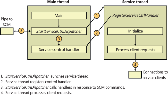
Figure 10-8 Inside a service process.
Service characteristics
The SCM stores each characteristic as a value in the service’s registry key. Figure 10-9 shows an example of a service registry key.
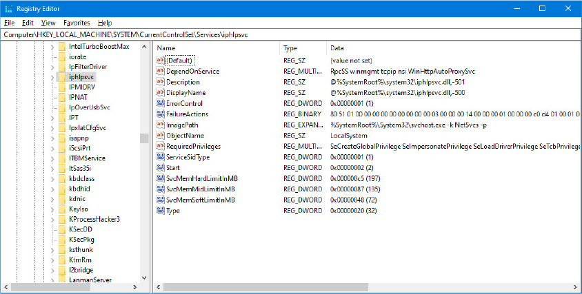
Figure 10-9 Example of a service registry key.
Table 10-7 lists all the service characteristics, many of which also apply to device drivers. (Not every characteristic applies to every type of service or device driver.)
Table 10-7 Service and Driver Registry Parameters
Value Setting |
Value Name |
Value Setting Description |
|---|---|---|
Start |
SERVICE_BOOT_START (0x0) |
Winload preloads the driver so that it is in memory during the boot. These drivers are initialized just prior to SERVICE_SYSTEM_START drivers. |
SERVICE_SYSTEM_START (0x1) |
The driver loads and initializes during kernel initialization after SERVICE_BOOT_START drivers have initialized. |
|
SERVICE_AUTO_START (0x2) |
The SCM starts the driver or service after the SCM process, Services.exe, starts. |
|
SERVICE_DEMAND_START (0x3) |
The SCM starts the driver or service on demand (when a client calls StartService on it, it is trigger started, or when another starting service is dependent on it.) |
|
SERVICE_DISABLED (0x4) |
The driver or service cannot be loaded or initialized. |
|
ErrorControl |
SERVICE_ERROR_IGNORE (0x0) |
Any error the driver or service returns is ignored, and no warning is logged or displayed. |
SERVICE_ERROR_NORMAL (0x1) |
If the driver or service reports an error, an event log message is written. |
|
SERVICE_ERROR_SEVERE (0x2) |
If the driver or service returns an error and last known good isn’t being used, reboot into last known good; otherwise, log an event message. |
|
SERVICE_ERROR_CRITICAL (0x3) |
If the driver or service returns an error and last known good isn’t being used, reboot into last known good; otherwise, log an event message. |
|
Type |
SERVICE_KERNEL_DRIVER (0x1) |
Device driver. |
SERVICE_FILE_SYSTEM_DRIVER (0x2) |
Kernel-mode file system driver. |
|
SERVICE_ADAPTER (0x4) |
Obsolete. |
|
SERVICE_RECOGNIZER_DRIVER (0x8) |
File system recognizer driver. |
|
SERVICE_WIN32_OWN_PROCESS (0x10) |
The service runs in a process that hosts only one service. |
|
SERVICE_WIN32_SHARE_PROCESS (0x20) |
The service runs in a process that hosts multiple services. |
|
SERVICE_USER_OWN_PROCESS (0x50) |
The service runs with the security token of the logged-in user in its own process. |
|
SERVICE_USER_SHARE_PROCESS (0x60) |
The service runs with the security token of the logged-in user in a process that hosts multiple services. |
|
SERVICE_INTERACTIVE_PROCESS (0x100) |
The service is allowed to display windows on the console and receive user input, but only on the console session (0) to prevent interacting with user/console applications on other sessions. This option is deprecated. |
|
Group |
Group name |
The driver or service initializes when its group is initialized. |
Tag |
Tag number |
The specified location in a group initialization order. This parameter doesn’t apply to services. |
ImagePath |
Path to the service or driver executable file |
If ImagePath isn’t specified, the I/O manager looks for drivers in %SystemRoot%System32Drivers. Required for Windows services. |
DependOnGroup |
Group name |
The driver or service won’t load unless a driver or service from the specified group loads. |
DependOnService |
Service name |
The service won’t load until after the specified service loads. This parameter doesn’t apply to device drivers or services with a start type different than SERVICE_AUTO_START or SERVICE_DEMAND_START. |
ObjectName |
Usually LocalSystem, but it can be an account name, such as .Administrator |
Specifies the account in which the service will run. If ObjectName isn’t specified, LocalSystem is the account used. This parameter doesn’t apply to device drivers. |
DisplayName |
Name of the service |
The service application shows services by this name. If no name is specified, the name of the service’s registry key becomes its name. |
DeleteFlag |
0 or 1 (TRUE or FALSE) |
Temporary flag set by the SCM when a service is marked to be deleted. |
Description |
Description of service |
Up to 32,767-byte description of the service. |
FailureActions |
Description of actions the SCM should take when the service process exits unexpectedly |
Failure actions include restarting the service process, rebooting the system, and running a specified program. This value doesn’t apply to drivers. |
FailureCommand |
Program command line |
The SCM reads this value only if FailureActions specifies that a program should execute upon service failure. This value doesn’t apply to drivers. |
DelayedAutoStart |
0 or 1 (TRUE or FALSE) |
Tells the SCM to start this service after a certain delay has passed since the SCM was started. This reduces the number of services starting simultaneously during startup. |
PreshutdownTimeout |
Timeout in milliseconds |
This value allows services to override the default preshutdown notification timeout of 180 seconds. After this timeout, the SCM performs shutdown actions on the service if it has not yet responded. |
ServiceSidType |
SERVICE_SID_TYPE_NONE (0x0) |
Backward-compatibility setting. |
SERVICE_SID_TYPE_UNRESTRICTED (0x1) |
The SCM adds the service SID as a group owner to the service process’s token when it is created. |
|
SERVICE_SID_TYPE_RESTRICTED (0x3) |
The SCM runs the service with a write-restricted token, adding the service SID to the restricted SID list of the service process, along with the world, logon, and write-restricted SIDs. |
|
Alias |
String |
Name of the service’s alias. |
RequiredPrivileges |
List of privileges |
This value contains the list of privileges that the service requires to function. The SCM computes their union when creating the token for the shared process related to this service, if any. |
Security |
Security descriptor |
This value contains the optional security descriptor that defines who has what access to the service object created internally by the SCM. If this value is omitted, the SCM applies a default security descriptor. |
LaunchProtected |
SERVICE_LAUNCH_PROTECTED_NONE (0x0) |
The SCM launches the service unprotected (default value). |
SERVICE_LAUNCH_PROTECTED_WINDOWS (0x1) |
The SCM launches the service in a Windows protected process. |
|
SERVICE_LAUNCH_PROTECTED_WINDOWS_ LIGHT (0x2) |
The SCM launches the service in a Windows protected process light. |
|
SERVICE_LAUNCH_PROTECTED_ANTIMALWARE_LIGHT (0x3) |
The SCM launches the service in an Antimalware protected process light. |
|
SERVICE_LAUNCH_PROTECTED_APP_LIGHT (0x4) |
The SCM launches the service in an App protected process light (internal only). |
|
UserServiceFlags |
USER_SERVICE_FLAG_DSMA_ALLOW (0x1) |
Allow the default user to start the user service. |
USER_SERVICE_FLAG_NONDSMA_ ALLOW (0x2) |
Do not allow the default user to start the service. |
|
SvcHostSplitDisable |
0 or 1 (TRUE or FALSE) |
When set to, 1 prohibits the SCM to enable Svchost splitting. This value applies only to shared services. |
PackageFullName |
String |
Package full name of a packaged service. |
AppUserModelId |
String |
Application user model ID (AUMID) of a packaged service. |
PackageOrigin |
PACKAGE_ORIGIN_UNSIGNED (0x1) PACKAGE_ORIGIN_INBOX (0x2) PACKAGE_ORIGIN_STORE (0x3) PACKAGE_ORIGIN_DEVELOPER_UNSIGNED (0x4) PACKAGE_ORIGIN_DEVELOPER_SIGNED (0x5) |
These values identify the origin of the AppX package (the entity that has created it). |
![]() Note
Note
The SCM does not access a service’s Parameters subkey until the service is deleted, at which time the SCM deletes the service’s entire key, including subkeys like Parameters.
Notice that Type values include three that apply to device drivers: device driver, file system driver, and file system recognizer. These are used by Windows device drivers, which also store their parameters as registry data in the Services registry key. The SCM is responsible for starting non-PNP drivers with a Start value of SERVICE_AUTO_START or SERVICE_DEMAND_START, so it’s natural for the SCM database to include drivers. Services use the other types, SERVICE_WIN32_OWN_PROCESS and SERVICE_WIN32_SHARE_PROCESS, which are mutually exclusive.
An executable that hosts just one service uses the SERVICE_WIN32_OWN_PROCESS type. In a similar way, an executable that hosts multiple services specifies the SERVICE_WIN32_SHARE_PROCESS. Hosting multiple services in a single process saves system resources that would otherwise be consumed as overhead when launching multiple service processes. A potential disadvantage is that if one of the services of a collection running in the same process causes an error that terminates the process, all the services of that process terminate. Also, another limitation is that all the services must run under the same account (however, if a service takes advantage of service security hardening mechanisms, it can limit some of its exposure to malicious attacks). The SERVICE_USER_SERVICE flag is added to denote a user service, which is a type of service that runs with the identity of the currently logged-on user
Trigger information is normally stored by the SCM under another subkey named TriggerInfo. Each trigger event is stored in a child key named as the event index, starting from 0 (for example, the third trigger event is stored in the “TriggerInfo2” subkey). Table 10-8 lists all the possible registry values that compose the trigger information.
Table 10-8 Triggered services registry parameters
Value Setting |
Value Name |
Value Setting Description |
|---|---|---|
Action |
SERVICE_TRIGGER_ACTION_SERVICE_ START (0x1) |
Start the service when the trigger event occurs. |
SERVICE_TRIGGER_ACTION_SERVICE_ STOP (0x2) |
Stop the service when the trigger event occurs. |
|
Type |
SERVICE_TRIGGER_TYPE_DEVICE_ INTERFACE_ARRIVAL (0x1) |
Specifies an event triggered when a device of the specified device interface class arrives or is present when the system starts. |
SERVICE_TRIGGER_TYPE_IP_ADDRESS_AVAILABILITY (0x2) |
Specifies an event triggered when an IP address becomes available or unavailable on the network stack. |
|
SERVICE_TRIGGER_TYPE_DOMAIN_JOIN (0x3) |
Specifies an event triggered when the computer joins or leaves a domain. |
|
SERVICE_TRIGGER_TYPE_FIREWALL_PORT_EVENT (0x4) |
Specifies an event triggered when a firewall port is opened or closed. |
|
SERVICE_TRIGGER_TYPE_GROUP_POLICY (0x5) |
Specifies an event triggered when a machine or user policy change occurs. |
|
SERVICE_TRIGGER_TYPE_NETWORK_ENDPOINT (0x6) |
Specifies an event triggered when a packet or request arrives on a particular network protocol. |
|
SERVICE_TRIGGER_TYPE_CUSTOM (0x14) |
Specifies a custom event generated by an ETW provider. |
|
Guid |
Trigger subtype GUID |
A GUID that identifies the trigger event subtype. The GUID depends on the Trigger type. |
Data[Index] |
Trigger-specific data |
Trigger-specific data for the service trigger event. This value depends on the trigger event type. |
DataType[Index] |
SERVICE_TRIGGER_DATA_TYPE_BINARY (0x1) |
The trigger-specific data is in binary format. |
SERVICE_TRIGGER_DATA_TYPE_STRING (0x2) |
The trigger-specific data is in string format. |
|
SERVICE_TRIGGER_DATA_TYPE_LEVEL (0x3) |
The trigger-specific data is a byte value. |
|
SERVICE_TRIGGER_DATA_TYPE_KEYWORD_ANY (0x4) |
The trigger-specific data is a 64-bit (8 bytes) unsigned integer value. |
|
SERVICE_TRIGGER_DATA_TYPE_KEYWORD_ALL (0x5) |
The trigger-specific data is a 64-bit (8 bytes) unsigned integer value. |
Service accounts
The security context of a service is an important consideration for service developers as well as for system administrators because it dictates which resource the process can access. Most built-in services run in the security context of an appropriate Service account (which has limited access rights, as described in the following subsections). When a service installation program or the system administrator creates a service, it usually specifies the security context of the local system account (displayed sometimes as SYSTEM and other times as LocalSystem), which is very powerful. Two other built-in accounts are the network service and local service accounts. These accounts have fewer capabilities than the local system account from a security standpoint. The following subsections describe the special characteristics of all the service accounts.
The local system account
The local system account is the same account in which core Windows user-mode operating system components run, including the Session Manager (%SystemRoot%System32Smss.exe), the Windows subsystem process (Csrss.exe), the Local Security Authority process (%SystemRoot%System32Lsass.exe), and the Logon process (%SystemRoot%System32Winlogon.exe). For more information on these processes, see Chapter 7 in Part 1.
From a security perspective, the local system account is extremely powerful—more powerful than any local or domain account when it comes to security ability on a local system. This account has the following characteristics:
■ It is a member of the local Administrators group. Table 10-9 shows the groups to which the local system account belongs. (See Chapter 7 in Part 1 for information on how group membership is used in object access checks.)
■ It has the right to enable all privileges (even privileges not normally granted to the local administrator account, such as creating security tokens). See Table 10-10 for the list of privileges assigned to the local system account. (Chapter 7 in Part 1 describes the use of each privilege.)
■ Most files and registry keys grant full access to the local system account. Even if they don’t grant full access, a process running under the local system account can exercise the take-ownership privilege to gain access.
■ Processes running under the local system account run with the default user profile (HKU.DEFAULT). Therefore, they can’t directly access configuration information stored in the user profiles of other accounts (unless they explicitly use the LoadUserProfile API).
■ When a system is a member of a Windows domain, the local system account includes the machine security identifier (SID) for the computer on which a service process is running. Therefore, a service running in the local system account will be automatically authenticated on other machines in the same forest by using its computer account. (A forest is a grouping of domains.)
■ Unless the machine account is specifically granted access to resources (such as network shares, named pipes, and so on), a process can access network resources that allow null sessions—that is, connections that require no credentials. You can specify the shares and pipes on a particular computer that permit null sessions in the NullSessionPipes and NullSessionShares registry values under HKLMSYSTEMCurrentControlSetServicesLanmanServerParameters.
Table 10-9 Service account group membership (and integrity level)
Local System |
Network Service |
Local Service |
Service Account |
|---|---|---|---|
Administrators Everyone Authenticated users System integrity level |
Everyone Users Authenticated users Local Network service Console logon System integrity level |
Everyone Users Authenticated users Local Local service Console logon UWP capabilities groups System integrity level |
Everyone Users Authenticated users Local Local service All services Write restricted Console logon High integrity Level |
Table 10-10 Service account privileges
Local System |
Local Service / Network Service |
Service Account |
|---|---|---|
SeAssignPrimaryTokenPrivilege SeAuditPrivilege SeBackupPrivilege SeChangeNotifyPrivilege SeCreateGlobalPrivilege SeCreatePagefilePrivilege SeCreatePermanentPrivilege SeCreateSymbolicLinkPrivilege SeCreateTokenPrivilege SeDebugPrivilege SeDelegateSessionUserImpersonatePrivilege SeImpersonatePrivilege SeIncreaseBasePriorityPrivilege SeIncreaseQuotaPrivilege SeIncreaseWorkingSetPrivilege SeLoadDriverPrivilege SeLockMemoryPrivilege SeManageVolumePrivilege SeProfileSingleProcessPrivilege SeRestorePrivilege SeSecurityPrivilege SeShutdownPrivilege SeSystemEnvironmentPrivilege SeSystemProfilePrivilege SeSystemtimePrivilege SeTakeOwnershipPrivilege SeTcbPrivilege SeTimeZonePrivilege SeTrustedCredManAccessPrivilege SeRelabelPrivilege SeUndockPrivilege (client only) |
SeAssignPrimaryTokenPrivilege SeAuditPrivilege SeChangeNotifyPrivilege SeCreateGlobalPrivilege SeImpersonatePrivilege SeIncreaseQuotaPrivilege SeIncreaseWorkingSetPrivilege SeShutdownPrivilege SeSystemtimePrivilege SeTimeZonePrivilege SeUndockPrivilege (client only) |
SeChangeNotifyPrivilege SeCreateGlobalPrivilege SeImpersonatePrivilege SeIncreaseWorkingSetPrivilege SeShutdownPrivilege SeTimeZonePrivilege SeUndockPrivilege |
The network service account
The network service account is intended for use by services that want to authenticate to other machines on the network using the computer account, as does the local system account, but do not have the need for membership in the Administrators group or the use of many of the privileges assigned to the local system account. Because the network service account does not belong to the Administrators group, services running in the network service account by default have access to far fewer registry keys, file system folders, and files than the services running in the local system account. Further, the assignment of few privileges limits the scope of a compromised network service process. For example, a process running in the network service account cannot load a device driver or open arbitrary processes.
Another difference between the network service and local system accounts is that processes running in the network service account use the network service account’s profile. The registry component of the network service profile loads under HKUS-1-5-20, and the files and directories that make up the component reside in %SystemRoot%ServiceProfilesNetworkService.
A service that runs in the network service account is the DNS client, which is responsible for resolving DNS names and for locating domain controllers.
The local service account
The local service account is virtually identical to the network service account with the important difference that it can access only network resources that allow anonymous access. Table 10-10 shows that the network service account has the same privileges as the local service account, and Table 10-9 shows that it belongs to the same groups with the exception that it belongs to the local service group instead of the network service group. The profile used by processes running in the local service loads into HKUS-1-5-19 and is stored in %SystemRoot%ServiceProfilesLocalService.
Examples of services that run in the local service account include the Remote Registry Service, which allows remote access to the local system’s registry, and the LmHosts service, which performs NetBIOS name resolution.
Running services in alternate accounts
Because of the restrictions just outlined, some services need to run with the security credentials of a user account. You can configure a service to run in an alternate account when the service is created or by specifying an account and password that the service should run under with the Windows Services MMC snap-in. In the Services snap-in, right-click a service and select Properties, click the Log On tab, and select the This Account option, as shown in Figure 10-10.
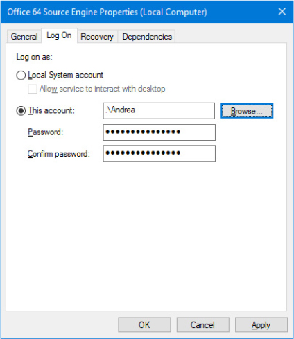
Figure 10-10 Service account settings.
Note that when required to start, a service running with an alternate account is always launched using the alternate account credentials, even though the account is not currently logged on. This means that the user profile is loaded even though the user is not logged on. User Services, which are described later in this chapter (in the “User services” section), have also been designed to overcome this problem. They are loaded only when the user logs on.
Running with least privilege
A service’s process typically is subject to an all-or-nothing model, meaning that all privileges available to the account the service process is running under are available to a service running in the process that might require only a subset of those privileges. To better conform to the principle of least privilege, in which Windows assigns services only the privileges they require, developers can specify the privileges their service requires, and the SCM creates a security token that contains only those privileges.
Service developers use the ChangeServiceConfig2 API (specifying the SERVICE_CONFIG_REQUIRED_PRIVILEGES _INFO information level) to indicate the list of privileges they desire. The API saves that information in the registry into the RequiredPrivileges value of the root service key (refer to Table 10-7). When the service starts, the SCM reads the key and adds those privileges to the token of the process in which the service is running.
If there is a RequiredPrivileges value and the service is a stand-alone service (running as a dedicated process), the SCM creates a token containing only the privileges that the service needs. For services running as part of a shared service process (as are a subset of services that are part of Windows) and specifying required privileges, the SCM computes the union of those privileges and combines them for the service-hosting process’s token. In other words, only the privileges not specified by any of the services that are hosted in the same service process will be removed. In the case in which the registry value does not exist, the SCM has no choice but to assume that the service is either incompatible with least privileges or requires all privileges to function. In this case, the full token is created, containing all privileges, and no additional security is offered by this model. To strip almost all privileges, services can specify only the Change Notify privilege.
![]() Note
Note
The privileges a service specifies must be a subset of those that are available to the service account in which it runs.
Use sc.exe to look at the required privileges specified by CryptSvc by typing the following into a command prompt:
sc qprivs cryptsvcYou should see three privileges being requested: the SeChangeNotifyPrivilege, SeCreateGlobalPrivilege, and the SeImpersonatePrivilege.
Run Process Explorer as administrator and look at the process list.
You should see multiple Svchost.exe processes that are hosting the services on your machine (in case Svchost splitting is enabled, the number of Svchost instances are even more). Process Explorer highlights these in pink.
CryptSvc is a service that runs in a shared hosting process. In Windows 10, locating the correct process instance is easily achievable through Task Manager. You do not need to know the name of the Service DLL, which is listed in the HKLMSYSTEMCurrentControlSetServicesCryptSvc Parameters registry key.
Open Task Manager and look at the Services tab. You should easily find the PID of the CryptSvc hosting process.
Return to Process Explorer and double-click the Svchost.exe process that has the same PID found by Task Manager to open the Properties dialog box.
Double check that the Services tab includes the CryptSvc service. If service splitting is enabled, it should contain only one service; otherwise, it will contain multiple services. Then click the Security tab. You should see security information similar to the following figure:
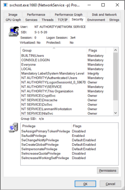
Service isolation
Although restricting the privileges that a service has access to helps lessen the ability of a compromised service process to compromise other processes, it does nothing to isolate the service from resources that the account in which it is running has access under normal conditions. As mentioned earlier, the local system account has complete access to critical system files, registry keys, and other securable objects on the system because the access control lists (ACLs) grant permissions to that account.
At times, access to some of these resources is critical to a service’s operation, whereas other objects should be secured from the service. Previously, to avoid running in the local system account to obtain access to required resources, a service would be run under a standard user account, and ACLs would be added on the system objects, which greatly increased the risk of malicious code attacking the system. Another solution was to create dedicated service accounts and set specific ACLs for each account (associated to a service), but this approach easily became an administrative hassle.
Windows now combines these two approaches into a much more manageable solution: it allows services to run in a nonprivileged account but still have access to specific privileged resources without lowering the security of those objects. Indeed, the ACLs on an object can now set permissions directly for a service, but not by requiring a dedicated account. Instead, Windows generates a service SID to represent a service, and this SID can be used to set permissions on resources such as registry keys and files.
The Service Control Manager uses service SIDs in different ways. If the service is configured to be launched using a virtual service account (in the NT SERVICE domain), a service SID is generated and assigned as the main user of the new service’s token. The token will also be part of the NT SERVICEALL SERVICES group. This group is used by the system to allow a securable object to be accessed by any service. In the case of shared services, the SCM creates the service-hosting processes (a process that contains more than one service) with a token that contains the service SIDs of all services that are part of the service group associated with the process, including services that are not yet started (there is no way to add new SIDs after a token has been created). Restricted and unrestricted services (explained later in this section) always have a service SID in the hosting process’s token.
The usefulness of having a SID for each service extends beyond the mere ability to add ACL entries and permissions for various objects on the system as a way to have fine-grained control over their access. Our discussion initially covered the case in which certain objects on the system, accessible by a given account, must be protected from a service running within that same account. As we’ve previously described, service SIDs prevent that problem only by requiring that Deny entries associated with the service SID be placed on every object that needs to be secured, which is a clearly an unmanageable approach.
To avoid requiring Deny access control entries (ACEs) as a way to prevent services from having access to resources that the user account in which they run does have access, there are two types of service SIDs: the restricted service SID (SERVICE_SID_TYPE_RESTRICTED) and the unrestricted service SID (SERVICE_SID_TYPE_UNRESTRICTED), the latter being the default and the case we’ve looked at up to now. The names are a little misleading in this case. The service SID is always generated in the same way (see the previous experiment). It is the token of the hosting process that is generated in a different way.
Unrestricted service SIDs are created as enabled-by-default, group owner SIDs, and the process token is also given a new ACE that provides full permission to the service logon SID, which allows the service to continue communicating with the SCM. (A primary use of this would be to enable or disable service SIDs inside the process during service startup or shutdown.) A service running with the SYSTEM account launched with an unrestricted token is even more powerful than a standard SYSTEM service.
A restricted service SID, on the other hand, turns the service-hosting process’s token into a write-restricted token. Restricted tokens (see Chapter 7 of Part 1 for more information on tokens) generally require the system to perform two access checks while accessing securable objects: one using the standard token’s enabled group SIDs list, and another using the list of restricted SIDs. For a standard restricted token, access is granted only if both access checks allow the requested access rights. On the other hand, write-restricted tokens (which are usually created by specifying the WRITE_RESTRICTED flag to the CreateRestrictedToken API) perform the double access checks only for write requests: read-only access requests raise just one access check on the token’s enabled group SIDs as for regular tokens.
The service host process running with a write-restricted token can write only to objects granting explicit write access to the service SID (and the following three supplemental SIDs added for compatibility), regardless of the account it’s running. Because of this, all services running inside that process (part of the same service group) must have the restricted SID type; otherwise, services with the restricted SID type fail to start. Once the token becomes write-restricted, three more SIDs are added for compatibility reasons:
■ The world SID is added to allow write access to objects that are normally accessible by anyone anyway, most importantly certain DLLs in the load path.
■ The service logon SID is added to allow the service to communicate with the SCM.
■ The write-restricted SID is added to allow objects to explicitly allow any write-restricted service write access to them. For example, ETW uses this SID on its objects to allow any write-restricted service to generate events.
Figure 10-11 shows an example of a service-hosting process containing services that have been marked as having restricted service SIDs. For example, the Base Filtering Engine (BFE), which is responsible for applying Windows Firewall filtering rules, is part of this hosting process because these rules are stored in registry keys that must be protected from malicious write access should a service be compromised. (This could allow a service exploit to disable the outgoing traffic firewall rules, enabling bidirectional communication with an attacker, for example.)
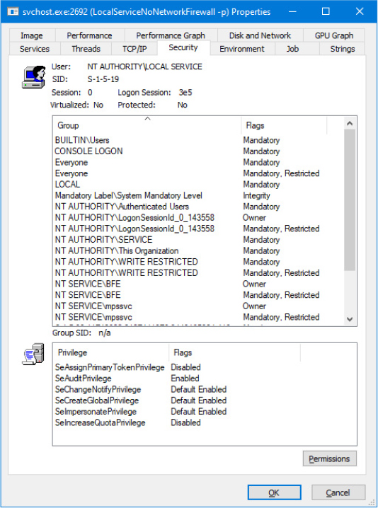
Figure 10-11 Service with restricted SIDs.
By blocking write access to objects that would otherwise be writable by the service (through inheriting the permissions of the account it is running as), restricted service SIDs solve the other side of the problem we initially presented because users do not need to do anything to prevent a service running in a privileged account from having write access to critical system files, registry keys, or other objects, limiting the attack exposure of any such service that might have been compromised.
Windows also allows for firewall rules that reference service SIDs linked to one of the three behaviors described in Table 10-11.
Table 10-11 Network restriction rules
Scenario |
Example |
Restrictions |
|---|---|---|
Network access blocked |
The shell hardware detection service (ShellHWDetection). |
All network communications are blocked (both incoming and outgoing). |
Network access statically port-restricted |
The RPC service (Rpcss) operates on port 135 (TCP and UDP). |
Network communications are restricted to specific TCP or UDP ports. |
Network access dynamically port-restricted |
The DNS service (Dns) listens on variable ports (UDP). |
Network communications are restricted to configurable TCP or UDP ports. |
The virtual service account
As introduced in the previous section, a service SID also can be set as the owner of the token of a service running in the context of a virtual service account. A service running with a virtual service account has fewer privileges than the LocalService or NetworkService service types (refer to Table 10-10 for the list of privileges) and no credentials available to authenticate it through the network. The Service SID is the token’s owner, and the token is part of the Everyone, Users, Authenticated Users, and All Services groups. This means that the service can read (or write, unless the service uses a restricted SID type) objects that belong to standard users but not to high-privileged ones belonging to the Administrator or System group. Unlike the other types, a service running with a virtual service account has a private profile, which is loaded by the ProfSvc service (Profsvc.dll) during service logon, in a similar way as for regular services (more details in the “Service logon” section). The profile is initially created during the first service logon using a folder with the same name as the service located in the %SystemRoot%ServiceProfiles path. When the service’s profile is loaded, its registry hive is mounted in the HKEY_USERS root key, under a key named as the virtual service account’s human readable SID (starting with S-1-5-80 as explained in the “Understanding service SIDs” experiment).
Users can easily assign a virtual service account to a service by setting the log-on account to NT SERVICE<ServiceName>, where <ServiceName> is the name of the service. At logon time, the Service Control Manager recognizes that the log-on account is a virtual service account (thanks to the NT SERVICE logon provider) and verifies that the account’s name corresponds to the name of the service. A service can’t be started using a virtual service account that belongs to another one, and this is enforced by SCM (through the internal ScIsValidAccountName function). Services that share a host process cannot run with a virtual service account.
While operating with securable objects, users can add to the object’s ACL using the service log-on account (in the form of NT SERVICE<ServiceName>), an ACE that allows or denies access to a virtual service. As shown in Figure 10-12, the system is able to translate the virtual service account’s name to the proper SID, thus establishing fine-grained access control to the object from the service. (This also works for regular services running with a nonsystem account, as explained in the previous section.)
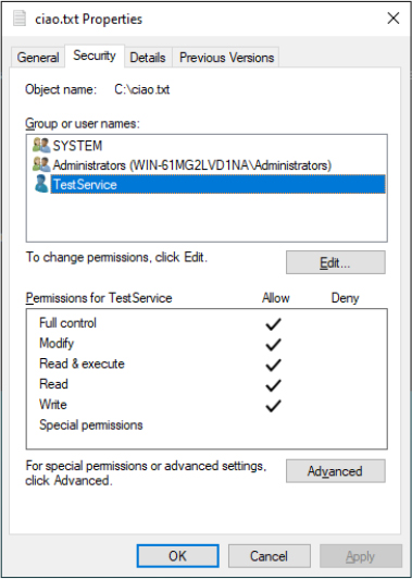
Figure 10-12 A file (securable object) with an ACE allowing full access to the TestService.
Interactive services and Session 0 Isolation
One restriction for services running under a proper service account, the local system, local service, and network service accounts that has always been present in Windows is that these services could not display dialog boxes or windows on the interactive user’s desktop. This limitation wasn’t the direct result of running under these accounts but rather a consequence of the way the Windows subsystem assigns service processes to window stations. This restriction is further enhanced by the use of sessions, in a model called Session 0 Isolation, a result of which is that services cannot directly interact with a user’s desktop.
The Windows subsystem associates every Windows process with a window station. A window station contains desktops, and desktops contain windows. Only one window station can be visible at a time and receive user mouse and keyboard input. In a Terminal Services environment, one window station per session is visible, but services all run as part of the hidden session 0. Windows names the visible window station WinSta0, and all interactive processes access WinSta0.
Unless otherwise directed, the Windows subsystem associates services running within the proper service account or the local system account with a nonvisible window station named Service-0x0-3e7$ that all noninteractive services share. The number in the name, 3e7, represents the logon session identifier that the Local Security Authority process (LSASS) assigns to the logon session the SCM uses for noninteractive services running in the local system account. In a similar way, services running in the Local service account are associated with the window station generated by the logon session 3e5, while services running in the network service account are associated with the window station generated by the logon session 3e4.
Services configured to run under a user account (that is, not the local system account) are run in a different nonvisible window station named with the LSASS logon identifier assigned for the service’s logon session. Figure 10-13 shows a sample display from the Sysinternals WinObj tool that shows the object manager directory in which Windows places window station objects. Visible are the interactive window station (WinSta0) and the three noninteractive services window stations.
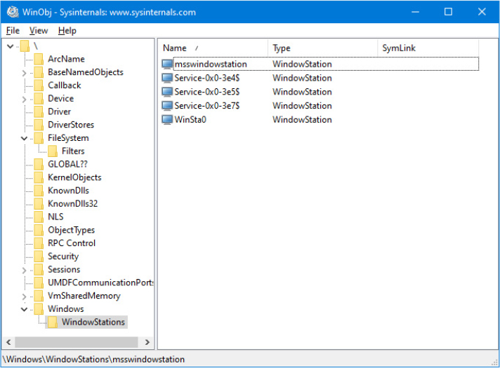
Figure 10-13 List of window stations.
Regardless of whether services are running in a user account, the local system account, or the local or network service accounts, services that aren’t running on the visible window station can’t receive input from a user or display visible windows. In fact, if a service were to pop up a modal dialog box, the service would appear hung because no user would be able to see the dialog box, which of course would prevent the user from providing keyboard or mouse input to dismiss it and allow the service to continue executing.
A service could have a valid reason to interact with the user via dialog boxes or windows. Services configured using the SERVICE_INTERACTIVE_PROCESS flag in the service’s registry key’s Type parameter are launched with a hosting process connected to the interactive WinSta0 window station. (Note that services configured to run under a user account can’t be marked as interactive.) Were user processes to run in the same session as services, this connection to WinSta0 would allow the service to display dialog boxes and windows and enable those windows to respond to user input because they would share the window station with the interactive services. However, only processes owned by the system and Windows services run in session 0; all other logon sessions, including those of console users, run in different sessions. Therefore, any window displayed by processes in session 0 is not visible to the user.
This additional boundary helps prevent shatter attacks, whereby a less-privileged application sends window messages to a window visible on the same window station to exploit a bug in a more privileged process that owns the window, which permits it to execute code in the more privileged process. In the past, Windows included the Interactive Services Detection service (UI0Detect), which notified users when a service had displayed a window on the main desktop of the WinSta0 window station of Session 0. This would allow the user to switch to the session 0’s window station, making interactive services run properly. For security purposes, this feature was first disabled; since Windows 10 April 2018 Update (RS4), it has been completely removed.
As a result, even though interactive services are still supported by the Service Control Manager (only by setting the HKLMSYSTEMCurrentControlSetControlWindowsNoInteractiveServices registry value to 0), access to session 0 is no longer possible. No service can display any window anymore (at least without some undocumented hack).
The Service Control Manager (SCM)
The SCM’s executable file is %SystemRoot%System32Services.exe, and like most service processes, it runs as a Windows console program. The Wininit process starts the SCM early during the system boot. (Refer to Chapter 12 for details on the boot process.) The SCM’s startup function, SvcCtrlMain, orchestrates the launching of services that are configured for automatic startup.
SvcCtrlMain first performs its own initialization by setting its process secure mitigations and unhandled exception filter and by creating an in-memory representation of the well-known SIDs. It then creates two synchronization events: one named SvcctrlStartEvent_A3752DX and the other named SC_AutoStartComplete. Both are initialized as nonsignaled. The first event is signaled by the SCM after all the steps necessary to receive commands from SCPs are completed. The second is signaled when the entire initialization of the SCM is completed. The event is used for preventing the system or other users from starting another instance of the Service Control Manager. The function that an SCP uses to establish a dialog with the SCM is OpenSCManager. OpenSCManager prevents an SCP from trying to contact the SCM before the SCM has initialized by waiting for SvcctrlStartEvent_A3752DX to become signaled.
Next, SvcCtrlMain gets down to business, creates a proper security descriptor, and calls ScGenerateServiceDB, the function that builds the SCM’s internal service database. ScGenerateServiceDB reads and stores the contents of HKLMSYSTEMCurrentControlSetControlServiceGroupOrderList, a REG_MULTI_SZ value that lists the names and order of the defined service groups. A service’s registry key contains an optional Group value if that service or device driver needs to control its startup ordering with respect to services from other groups. For example, the Windows networking stack is built from the bottom up, so networking services must specify Group values that place them later in the startup sequence than networking device drivers. The SCM internally creates a group list that preserves the ordering of the groups it reads from the registry. Groups include (but are not limited to) NDIS, TDI, Primary Disk, Keyboard Port, Keyboard Class, Filters, and so on. Add-on and third-party applications can even define their own groups and add them to the list. Microsoft Transaction Server, for example, adds a group named MS Transactions.
ScGenerateServiceDB then scans the contents of HKLMSYSTEMCurrentControlSetServices, creating an entry (called “service record”) in the service database for each key it encounters. A database entry includes all the service-related parameters defined for a service as well as fields that track the service’s status. The SCM adds entries for device drivers as well as for services because the SCM starts services and drivers marked as autostart and detects startup failures for drivers marked boot-start and system-start. It also provides a means for applications to query the status of drivers. The I/O manager loads drivers marked boot-start and system-start before any user-mode processes execute, and therefore any drivers having these start types load before the SCM starts.
ScGenerateServiceDB reads a service’s Group value to determine its membership in a group and associates this value with the group’s entry in the group list created earlier. The function also reads and records in the database the service’s group and service dependencies by querying its DependOnGroup and DependOnService registry values. Figure 10-14 shows how the SCM organizes the service entry and group order lists. Notice that the service list is sorted alphabetically. The reason this list is sorted alphabetically is that the SCM creates the list from the Services registry key, and Windows enumerates registry keys alphabetically.

Figure 10-14 Organization of the service database.
During service startup, the SCM calls on LSASS (for example, to log on a service in a nonlocal system account), so the SCM waits for LSASS to signal the LSA_RPC_SERVER_ACTIVE synchronization event, which it does when it finishes initializing. Wininit also starts the LSASS process, so the initialization of LSASS is concurrent with that of the SCM, and the order in which LSASS and the SCM complete initialization can vary. The SCM cleans up (from the registry, other than from the database) all the services that were marked as deleted (through the DeleteFlag registry value) and generates the dependency list for each service record in the database. This allows the SCM to know which service is dependent on a particular service record, which is the opposite dependency information compared to the one stored in the registry.
The SCM then queries whether the system is started in safe mode (from the HKLMSystemCurrentControlSet ControlSafebootOptionOptionValue registry value). This check is needed for determining later if a service should start (details are explained in the “Autostart services startup” section later in this chapter). It then creates its remote procedure call (RPC) named pipe, which is named PipeNtsvcs, and then RPC launches a thread to listen on the pipe for incoming messages from SCPs. The SCM signals its initialization-complete event, SvcctrlStartEvent_A3752DX. Registering a console application shutdown event handler and registering with the Windows subsystem process via RegisterServiceProcess prepares the SCM for system shutdown.
Before starting the autostart services, the SCM performs a few more steps. It initializes the UMDF driver manager, which is responsible in managing UMDF drivers. Since Windows 10 Fall Creators Update (RS3), it’s part of the Service Control Manager and waits for the known DLLs to be fully initialized (by waiting on the KnownDllsSmKnownDllsInitialized event that’s signaled by Session Manager).
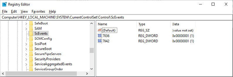
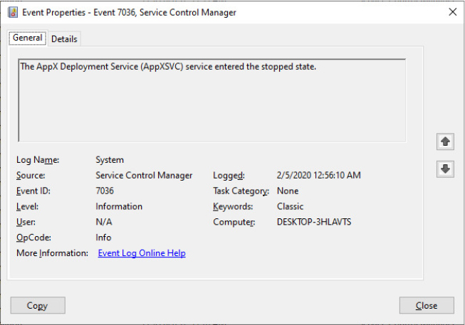
Network drive letters
In addition to its role as an interface to services, the SCM has another totally unrelated responsibility: It notifies GUI applications in a system whenever the system creates or deletes a network drive-letter connection. The SCM waits for the Multiple Provider Router (MPR) to signal a named event, BaseNamedObjectsScNetDrvMsg, which MPR signals whenever an application assigns a drive letter to a remote network share or deletes a remote-share drive-letter assignment. When MPR signals the event, the SCM calls the GetDriveType Windows function to query the list of connected network drive letters. If the list changes across the event signal, the SCM sends a Windows broadcast message of type WM_DEVICECHANGE. The SCM uses either DBT_DEVICEREMOVECOMPLETE or DBT_DEVICEARRIVAL as the message’s subtype. This message is primarily intended for Windows Explorer so that it can update any open computer windows to show the presence or absence of a network drive letter.
Service control programs
As introduced in the “Service applications” section, service control programs (SCPs) are standard Windows applications that use SCM service management functions, including CreateService, OpenService, StartService, ControlService, QueryServiceStatus, and DeleteService. To use the SCM functions, an SCP must first open a communications channel to the SCM by calling the OpenSCManager function to specify what types of actions it wants to perform. For example, if an SCP simply wants to enumerate and display the services present in the SCM’s database, it requests enumerate-service access in its call to OpenSCManager. During its initialization, the SCM creates an internal object that represents the SCM database and uses the Windows security functions to protect the object with a security descriptor that specifies what accounts can open the object with what access permissions. For example, the security descriptor indicates that the Authenticated Users group can open the SCM object with enumerate-service access. However, only administrators can open the object with the access required to create or delete a service.
As it does for the SCM database, the SCM implements security for services themselves. When an SCP creates a service by using the CreateService function, it specifies a security descriptor that the SCM associates internally with the service’s entry in the service database. The SCM stores the security descriptor in the service’s registry key as the Security value, and it reads that value when it scans the registry’s Services key during initialization so that the security settings persist across reboots. In the same way that an SCP must specify what types of access it wants to the SCM database in its call to OpenSCManager, an SCP must tell the SCM what access it wants to a service in a call to OpenService. Accesses that an SCP can request include the ability to query a service’s status and to configure, stop, and start a service.
The SCP you’re probably most familiar with is the Services MMC snap-in that’s included in Windows, which resides in %SystemRoot%System32Filemgmt.dll. Windows also includes Sc.exe (Service Controller tool), a command-line service control program that we’ve mentioned multiple times.
SCPs sometimes layer service policy on top of what the SCM implements. A good example is the timeout that the Services MMC snap-in implements when a service is started manually. The snap-in presents a progress bar that represents the progress of a service’s startup. Services indirectly interact with SCPs by setting their configuration status to reflect their progress as they respond to SCM commands such as the start command. SCPs query the status with the QueryServiceStatus function. They can tell when a service actively updates the status versus when a service appears to be hung, and the SCM can take appropriate actions in notifying a user about what the service is doing.
Autostart services startup
SvcCtrlMain invokes the SCM function ScAutoStartServices to start all services that have a Start value designating autostart (except delayed autostart and user services). ScAutoStartServices also starts autostart drivers. To avoid confusion, you should assume that the term services means services and drivers unless indicated otherwise. ScAutoStartServices begins by starting two important and basic services, named Plug and Play (implemented in the Umpnpmgr.dll library) and Power (implemented in the Umpo.dll library), which are needed by the system for managing plug-and-play hardware and power interfaces. The SCM then registers its Autostart WNF state, used to indicate the current autostart phase to the Power and other services.
Before the starting of other services can begin, the ScAutoStartService routine calls ScGetBootAnd SystemDriverState to scan the service database looking for boot-start and system-start device driver entries. ScGetBootAndSystemDriverState determines whether a driver with the start type set to Boot Start or System Start successfully started by looking up its name in the object manager namespace directory named Driver. When a device driver successfully loads, the I/O manager inserts the driver’s object in the namespace under this directory, so if its name isn’t present, it hasn’t loaded. Figure 10-15 shows WinObj displaying the contents of the Driver directory. ScGetBootAndSystemDriverState notes the names of drivers that haven’t started and that are part of the current profile in a list named ScStoppedDrivers. The list will be used later at the end of the SCM initialization for logging an event to the system event log (ID 7036), which contains the list of boot drivers that have failed to start.
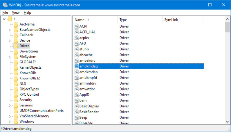
Figure 10-15 List of driver objects.
The algorithm in ScAutoStartServices for starting services in the correct order proceeds in phases, whereby a phase corresponds to a group and phases proceed in the sequence defined by the group ordering stored in the HKLMSYSTEMCurrentControlSetControlServiceGroupOrderList registry value. The List value, shown in Figure 10-16, includes the names of groups in the order that the SCM should start them. Thus, assigning a service to a group has no effect other than to fine-tune its startup with respect to other services belonging to different groups.

Figure 10-16 ServiceGroupOrder registry key.
When a phase starts, ScAutoStartServices marks all the service entries belonging to the phase’s group for startup. Then ScAutoStartServices loops through the marked services to see whether it can start each one. Part of this check includes seeing whether the service is marked as delayed autostart or a user template service; in both cases, the SCM will start it at a later stage. (Delayed autostart services must also be ungrouped. User services are discussed later in the “User services” section.) Another part of the check it makes consists of determining whether the service has a dependency on another group, as specified by the existence of the DependOnGroup value in the service’s registry key. If a dependency exists, the group on which the service is dependent must have already initialized, and at least one service of that group must have successfully started. If the service depends on a group that starts later than the service’s group in the group startup sequence, the SCM notes a “circular dependency” error for the service. If ScAutoStartServices is considering a Windows service or an autostart device driver, it next checks to see whether the service depends on one or more other services; if it is dependent, it determines whether those services have already started. Service dependencies are indicated with the DependOnService registry value in a service’s registry key. If a service depends on other services that belong to groups that come later in the ServiceGroupOrderList, the SCM also generates a “circular dependency” error and doesn’t start the service. If the service depends on any services from the same group that haven’t yet started, the service is skipped.
When the dependencies of a service have been satisfied, ScAutoStartServices makes a final check to see whether the service is part of the current boot configuration before starting the service. When the system is booted in safe mode, the SCM ensures that the service is either identified by name or by group in the appropriate safe boot registry key. There are two safe boot keys, Minimal and Network, under HKLMSYSTEMCurrentControlSetControlSafeBoot, and the one that the SCM checks depends on what safe mode the user booted. If the user chose Safe Mode or Safe Mode With Command Prompt at the modern or legacy boot menu, the SCM references the Minimal key; if the user chose Safe Mode With Networking, the SCM refers to Network. The existence of a string value named Option under the SafeBoot key indicates not only that the system booted in safe mode but also the type of safe mode the user selected. For more information about safe boots, see the section “Safe mode” in Chapter 12.
Service start
Once the SCM decides to start a service, it calls StartInternal, which takes different steps for services than for device drivers. When StartInternal starts a Windows service, it first determines the name of the file that runs the service’s process by reading the ImagePath value from the service’s registry key. If the service file corresponds to LSASS.exe, the SCM initializes a control pipe, connects to the already-running LSASS process, and waits for the LSASS process response. When the pipe is ready, the LSASS process connects to the SCM by calling the classical StartServiceCtrlDispatcher routine. As shown in Figure 10-17, some services like Credential Manager or Encrypting File System need to cooperate with the Local Security Authority Subsystem Service (LSASS)—usually for performing cryptography operation for the local system policies (like passwords, privileges, and security auditing. See Chapter 7 of Part 1 for more details).

Figure 10-17 Services hosted by the Local Security Authority Subsystem Service (LSASS) process.
The SCM then determines whether the service is critical (by analyzing the FailureAction registry value) or is running under WoW64. (If the service is a 32-bit service, the SCM should apply file system redirection. See the “WoW64” section of Chapter 8 for more details.) It also examines the service’s Type value. If the following conditions apply, the SCM initiates a search in the internal Image Record Database:
■ The service type value includes SERVICE_WINDOWS_SHARE_PROCESS (0x20).
■ The service has not been restarted after an error.
■ Svchost service splitting is not allowed for the service (see the “Svchost service splitting” section later in this chapter for further details).
An Image record is a data structure that represents a launched process hosting at least one service. If the preceding conditions apply, the SCM searches an image record that has the same process executable’s name as the new service ImagePath value.
If the SCM locates an existing image database entry with matching ImagePath data, the service can be shared, and one of the hosting processes is already running. The SCM ensures that the found hosting process is logged on using the same account as the one specified for the service being started. (This is to ensure that the service is not configured with the wrong account, such as a LocalService account, but with an image path pointing to a running Svchost, such as netsvcs, which runs as LocalSystem.) A service’s ObjectName registry value stores the user account in which the service should run. A service with no ObjectName or an ObjectName of LocalSystem runs in the local system account. A process can be logged on as only one account, so the SCM reports an error when a service specifies a different account name than another service that has already started in the same process.
If the image record exists, before the new service can be run, another final check should be performed: The SCM opens the token of the currently executing host process and checks whether the necessary service SID is located in the token (and all the required privileges are enabled). Even in this case, the SCM reports an error if the condition is not verified. Note that, as we describe in the next section (“Service logon”), for shared services, all the SIDs of the hosted services are added at token creation time. It is not possible for any user-mode component to add group SIDs in a token after the token has already been created.
If the image database doesn’t have an entry for the new service ImagePath value, the SCM creates one. When the SCM creates a new entry, it stores the logon account name used for the service and the data from the service’s ImagePath value. The SCM requires services to have an ImagePath value. If a service doesn’t have an ImagePath value, the SCM reports an error stating that it couldn’t find the service’s path and isn’t able to start the service. After the SCM creates an image record, it logs on the service account and starts the new hosting process. (The procedure is described in the next section, “Service logon.”)
After the service has been logged in, and the host process correctly started, the SCM waits for the initial “connection” message from the service. The service connects to SCM thanks to the SCM RPC pipe (PipeNtsvcs, as described in the “The Service Control Manager” section) and to a Channel Context data structure built by the LogonAndStartImage routine. When the SCM receives the first message, it proceeds to start the service by posting a SERVICE_CONTROL_START control message to the service process. Note that in the described communication protocol is always the service that connects to SCM.
The service application is able to process the message thanks to the message loop located in the StartServiceCtrlDispatcher API (see the “Service applications” section earlier in this chapter for more details). The service application enables the service group SID in its token (if needed) and creates the new service thread (which will execute the Service Main function). It then calls back into the SCM for creating a handle to the new service, storing it in an internal data structure (INTERNAL_DISPATCH_TABLE) similar to the service table specified as input to the StartServiceCtrlDispatcher API. The data structure is used for tracking the active services in the hosting process. If the service fails to respond positively to the start command within the timeout period, the SCM gives up and notes an error in the system Event Log that indicates the service failed to start in a timely manner.
If the service the SCM starts with a call to StartInternal has a Type registry value of SERVICE_KERNEL_DRIVER or SERVICE_FILE_SYSTEM_DRIVER, the service is really a device driver, so StartInternal enables the load driver security privilege for the SCM process and then invokes the kernel service NtLoadDriver, passing in the data in the ImagePath value of the driver’s registry key. Unlike services, drivers don’t need to specify an ImagePath value, and if the value is absent, the SCM builds an image path by appending the driver’s name to the string %SystemRoot%System32 Drivers.
![]() Note
Note
A device driver with the start value of SERVICE_AUTO_START or SERVICE_DEMAND_START is started by the SCM as a runtime driver, which implies that the resulting loaded image uses shared pages and has a control area that describes them. This is different than drivers with the start value of SERVICE_BOOT_START or SERVICE_SYSTEM_START, which are loaded by the Windows Loader and started by the I/O manager. Those drivers all use private pages and are neither sharable nor have an associated Control Area.
More details are available in Chapter 5 in Part 1.
ScAutoStartServices continues looping through the services belonging to a group until all the services have either started or generated dependency errors. This looping is the SCM’s way of automatically ordering services within a group according to their DependOnService dependencies. The SCM starts the services that other services depend on in earlier loops, skipping the dependent services until subsequent loops. Note that the SCM ignores Tag values for Windows services, which you might come across in subkeys under the HKLMSYSTEMCurrentControlSetServices key; the I/O manager honors Tag values to order device driver startup within a group for boot-start and system-start drivers. Once the SCM completes phases for all the groups listed in the ServiceGroupOrderList value, it performs a phase for services belonging to groups not listed in the value and then executes a final phase for services without a group.
After handling autostart services, the SCM calls ScInitDelayStart, which queues a delayed work item associated with a worker thread responsible for processing all the services that ScAutoStartServices skipped because they were marked delayed autostart (through the DelayedAutostart registry value). This worker thread will execute after the delay. The default delay is 120 seconds, but it can be overridden by the creating an AutoStartDelay value in HKLMSYSTEMCurrentControlSetControl. The SCM performs the same actions as those executed during startup of nondelayed autostart services.
When the SCM finishes starting all autostart services and drivers, as well as setting up the delayed autostart work item, the SCM signals the event BaseNamedObjectsSC_AutoStartComplete. This event is used by the Windows Setup program to gauge startup progress during installation.
Service logon
During the start procedure, if the SCM does not find any existing image record, it means that the host process needs to be created. Indeed, the new service is not shareable, it’s the first one to be executed, it has been restarted, or it’s a user service. Before starting the process, the SCM should create an access token for the service host process. The LogonAndStartImage function’s goal is to create the token and start the service’s host process. The procedure depends on the type of service that will be started.
User services (more precisely user service instances) are started by retrieving the current logged-on user token (through functions implemented in the UserMgr.dll library). In this case, the LogonAndStartImage function duplicates the user token and adds the “WIN://ScmUserService” security attribute (the attribute value is usually set to 0). This security attribute is used primarily by the Service Control Manager when receiving connection requests from the service. Although SCM can recognize a process that’s hosting a classical service through the service SID (or the System account SID if the service is running under the Local System Account), it uses the SCM security attribute for identifying a process that’s hosting a user service.
For all other type of services, the SCM reads the account under which the service will be started from the registry (from the ObjectName value) and calls ScCreateServiceSids with the goal to create a service SID for each service that will be hosted by the new process. (The SCM cycles between each service in its internal service database.) Note that if the service runs under the LocalSystem account (with no restricted nor unrestricted SID), this step is not executed.
The SCM logs on services that don’t run in the System account by calling the LSASS function LogonUserExEx. LogonUserExEx normally requires a password, but normally the SCM indicates to LSASS that the password is stored as a service’s LSASS “secret” under the key HKLMSECURITYPolicySecrets in the registry. (Keep in mind that the contents of SECURITY aren’t typically visible because its default security settings permit access only from the System account.) When the SCM calls LogonUserExEx, it specifies a service logon as the logon type, so LSASS looks up the password in the Secrets subkey that has a name in the form _SC_<Service Name>.
![]() Note
Note
Services running with a virtual service account do not need a password for having their service token created by the LSA service. For those services, the SCM does not provide any password to the LogonUserExEx API.
The SCM directs LSASS to store a logon password as a secret using the LsaStorePrivateData function when an SCP configures a service’s logon information. When a logon is successful, LogonUserEx returns a handle to an access token to the caller. The SCM adds the necessary service SIDs to the returned token, and, if the new service uses restricted SIDs, invokes the ScMakeServiceTokenWriteRestricted function, which transforms the token in a write-restricted token (adding the proper restricted SIDs). Windows uses access tokens to represent a user’s security context, and the SCM later associates the access token with the process that implements the service.
Next, the SCM creates the user environment block and security descriptor to associate with the new service process. In case the service that will be started is a packaged service, the SCM reads all the package information from the registry (package full name, origin, and application user model ID) and calls the Appinfo service, which stamps the token with the necessary AppModel security attributes and prepares the service process for the modern package activation. (See the “Packaged applications” section in Chapter 8 for more details about the AppModel.)
After a successful logon, the SCM loads the account’s profile information, if it’s not already loaded, by calling the User Profile Basic Api DLL’s (%SystemRoot%System32Profapi.dll) LoadProfileBasic function. The value HKLMSOFTWAREMicrosoftWindows NTCurrentVersionProfileList<user profile key>ProfileImagePath contains the location on disk of a registry hive that LoadUserProfile loads into the registry, making the information in the hive the HKEY_CURRENT_USER key for the service.
As its next step, LogonAndStartImage proceeds to launch the service’s process. The SCM starts the process in a suspended state with the CreateProcessAsUser Windows function. (Except for a process hosting services under a local system account, which are created through the standard CreateProcess API. The SCM already runs with a SYSTEM token, so there is no need of any other logon.)
Before the process is resumed, the SCM creates the communication data structure that allows the service application and the SCM to communicate through asynchronous RPCs. The data structure contains a control sequence, a pointer to a control and response buffer, service and hosting process data (like the PID, the service SID, and so on), a synchronization event, and a pointer to the async RPC state.
The SCM resumes the service process via the ResumeThread function and waits for the service to connect to its SCM pipe. If it exists, the registry value HKLMSYSTEMCurrentControlSetControlServicesPipeTimeout determines the length of time that the SCM waits for a service to call StartServiceCtrlDispatcher and connect before it gives up, terminates the process, and concludes that the service failed to start (note that in this case the SCM terminates the process, unlike when the service doesn’t respond to the start request, discussed previously in the “Service start” section). If ServicesPipeTimeout doesn’t exist, the SCM uses a default timeout of 30 seconds. The SCM uses the same timeout value for all its service communications.
Delayed autostart services
Delayed autostart services enable Windows to cope with the growing number of services that are being started when a user logs on, which bogs down the boot-up process and increases the time before a user is able to get responsiveness from the desktop. The design of autostart services was primarily intended for services required early in the boot process because other services depend on them, a good example being the RPC service, on which all other services depend. The other use was to allow unattended startup of a service, such as the Windows Update service. Because many autostart services fall in this second category, marking them as delayed autostart allows critical services to start faster and for the user’s desktop to be ready sooner when a user logs on immediately after booting. Additionally, these services run in background mode, which lowers their thread, I/O, and memory priority. Configuring a service for delayed autostart requires calling the ChangeServiceConfig2 API. You can check the state of the flag for a service by using the qc option of sc.exe.
![]() Note
Note
If a nondelayed autostart service has a delayed autostart service as one of its dependencies, the delayed autostart flag is ignored and the service is started immediately to satisfy the dependency.
Triggered-start services
Some services need to be started on demand, after certain system events occur. For that reason, Windows 7 introduced the concept of triggered-start service. A service control program can use the ChangeServiceConfig2 API (by specifying the SERVICE_CONFIG_TRIGGER_INFO information level) for configuring a demand-start service to be started (or stopped) after one or more system events occur. Examples of system events include the following:
■ A specific device interface is connected to the system.
■ The computer joins or leaves a domain.
■ A TCP/IP port is opened or closed in the system firewall.
■ A machine or user policy has been changed.
■ An IP address on the network TCP/IP stack becomes available or unavailable.
■ A RPC request or Named pipe packet arrives on a particular interface.
■ An ETW event has been generated in the system.
The first implementation of triggered-start services relied on the Unified Background Process Manager (see the next section for details). Windows 8.1 introduced the Broker Infrastructure, which had the main goal of managing multiple system events targeted to Modern apps. All the previously listed events have been thus begun to be managed by mainly three brokers, which are all parts of the Broker Infrastructure (with the exception of the Event Aggregation): Desktop Activity Broker, System Event Broker, and the Event Aggregation. More information on the Broker Infrastructure is available in the “Packaged applications” section of Chapter 8.
After the first phase of ScAutoStartServices is complete (which usually starts critical services listed in the HKLMSYSTEMCurrentControlSetControlEarlyStartServices registry value), the SCM calls ScRegisterServicesForTriggerAction, the function responsible in registering the triggers for each triggered-start service. The routine cycles between each Win32 service located in the SCM database. For each service, the function generates a temporary WNF state name (using the NtCreateWnfStateName native API), protected by a proper security descriptor, and publishes it with the service status stored as state data. (WNF architecture is described in the “Windows Notification Facility” section of Chapter 8.) This WNF state name is used for publishing services status changes. The routine then queries all the service triggers from the TriggerInfo registry key, checking their validity and bailing out in case no triggers are available.
![]() Note
Note
The list of supported triggers, described previously, together with their parameters, is documented at https://docs.microsoft.com/en-us/windows/win32/api/winsvc/ns-winsvc-service_trigger.
If the check succeeded, for each trigger the SCM builds an internal data structure containing all the trigger information (like the targeted service name, SID, broker name, and trigger parameters) and determines the correct broker based on the trigger type: external devices events are managed by the System Events broker, while all the other types of events are managed by the Desktop Activity broker. The SCM at this stage is able to call the proper broker registration routine. The registration process is private and depends on the broker: multiple private WNF state names (which are broker specific) are generated for each trigger and condition.
The Event Aggregation broker is the glue between the private WNF state names published by the two brokers and the Service Control Manager. It subscribes to all the WNF state names corresponding to the triggers and the conditions (by using the RtlSubscribeWnfStateChangeNotification API). When enough WNF state names have been signaled, the Event Aggregation calls back the SCM, which can start or stop the triggered start service.
Differently from the WNF state names used for each trigger, the SCM always independently publishes a WNF state name for each Win32 service whether or not the service has registered some triggers. This is because an SCP can receive notification when the specified service status changes by invoking the NotifyServiceStatusChange API, which subscribes to the service’s status WNF state name. Every time the SCM raises an event that changes the status of a service, it publishes new state data to the “service status change” WNF state, which wakes up a thread running the status change callback function in the SCP.
Startup errors
If a driver or a service reports an error in response to the SCM’s startup command, the ErrorControl value of the service’s registry key determines how the SCM reacts. If the ErrorControl value is SERVICE_ERROR_IGNORE (0) or the ErrorControl value isn’t specified, the SCM simply ignores the error and continues processing service startups. If the ErrorControl value is SERVICE_ERROR_NORMAL (1), the SCM writes an event to the system Event Log that says, “The <service name> service failed to start due to the following error.” The SCM includes the textual representation of the Windows error code that the service returned to the SCM as the reason for the startup failure in the Event Log record. Figure 10-18 shows the Event Log entry that reports a service startup error.

Figure 10-18 Service startup failure Event Log entry.
If a service with an ErrorControl value of SERVICE_ERROR_SEVERE (2) or SERVICE_ERROR_CRITICAL (3) reports a startup error, the SCM logs a record to the Event Log and then calls the internal function ScRevertToLastKnownGood. This function checks whether the last known good feature is enabled, and, if so, switches the system’s registry configuration to a version, named last known good, with which the system last booted successfully. Then it restarts the system using the NtShutdownSystem system service, which is implemented in the executive. If the system is already booting with the last known good configuration, or if the last known good configuration is not enabled, the SCM does nothing more than emit a log event.
Accepting the boot and last known good
Besides starting services, the system charges the SCM with determining when the system’s registry configuration, HKLMSYSTEMCurrentControlSet, should be saved as the last known good control set. The CurrentControlSet key contains the Services key as a subkey, so CurrentControlSet includes the registry representation of the SCM database. It also contains the Control key, which stores many kernel-mode and user-mode subsystem configuration settings. By default, a successful boot consists of a successful startup of autostart services and a successful user logon. A boot fails if the system halts because a device driver crashes the system during the boot or if an autostart service with an ErrorControl value of SERVICE_ERROR_SEVERE or SERVICE_ERROR_CRITICAL reports a startup error.
The last known good configuration feature is usually disabled in the client version of Windows. It can be enabled by setting the HKLMSYSTEMCurrentControlSetControlSession ManagerConfiguration ManagerLastKnownGoodEnabled registry value to 1. In Server SKUs of Windows, the value is enabled by default.
The SCM knows when it has completed a successful startup of the autostart services, but Winlogon (%SystemRoot%System32Winlogon.exe) must notify it when there is a successful logon. Winlogon invokes the NotifyBootConfigStatus function when a user logs on, and NotifyBootConfigStatus sends a message to the SCM. Following the successful start of the autostart services or the receipt of the message from NotifyBootConfigStatus (whichever comes last), if the last known good feature is enabled, the SCM calls the system function NtInitializeRegistry to save the current registry startup configuration.
Third-party software developers can supersede Winlogon’s definition of a successful logon with their own definition. For example, a system running Microsoft SQL Server might not consider a boot successful until after SQL Server is able to accept and process transactions. Developers impose their definition of a successful boot by writing a boot-verification program and installing the program by pointing to its location on disk with the value stored in the registry key HKLMSYSTEMCurrentControlSetControlBootVerificationProgram. In addition, a boot-verification program’s installation must disable Winlogon’s call to NotifyBootConfigStatus by setting HKLMSOFTWAREMicrosoftWindows NTCurrentVersionWinlogonReportBootOk to 0. When a boot-verification program is installed, the SCM launches it after finishing autostart services and waits for the program’s call to NotifyBootConfigStatus before saving the last known good control set.
Windows maintains several copies of CurrentControlSet, and CurrentControlSet is really a symbolic registry link that points to one of the copies. The control sets have names in the form HKLMSYSTEMControlSetnnn, where nnn is a number such as 001 or 002. The HKLMSYSTEMSelect key contains values that identify the role of each control set. For example, if CurrentControlSet points to ControlSet001, the Current value under Select has a value of 1. The LastKnownGood value under Select contains the number of the last known good control set, which is the control set last used to boot successfully. Another value that might be on your system under the Select key is Failed, which points to the last control set for which the boot was deemed unsuccessful and aborted in favor of an attempt at booting with the last known good control set. Figure 10-19 displays a Windows Server system’s control sets and Select values.

Figure 10-19 Control set selection key on Windows Server 2019.
NtInitializeRegistry takes the contents of the last known good control set and synchronizes it with that of the CurrentControlSet key’s tree. If this was the system’s first successful boot, the last known good won’t exist, and the system will create a new control set for it. If the last known good tree exists, the system simply updates it with differences between it and CurrentControlSet.
Last known good is helpful in situations in which a change to CurrentControlSet, such as the modification of a system performance-tuning value under HKLMSYSTEMControl or the addition of a service or device driver, causes the subsequent boot to fail. Figure 10-20 shows the Startup Settings of the modern boot menu. Indeed, when the Last Known Good feature is enabled, and the system is in the boot process, users can select the Startup Settings choice in the Troubleshoot section of the modern boot menu (or in the Windows Recovery Environment) to bring up another menu that lets them direct the boot to use the last known good control set. (In case the system is still using the Legacy boot menu, users should press F8 to enable the Advanced Boot Options.) As shown in the figure, when the Enable Last Known Good Configuration option is selected, the system boots by rolling the system’s registry configuration back to the way it was the last time the system booted successfully. Chapter 12 describes in more detail the use of the Modern boot menu, the Windows Recovery Environment, and other recovery mechanisms for troubleshooting system startup problems.
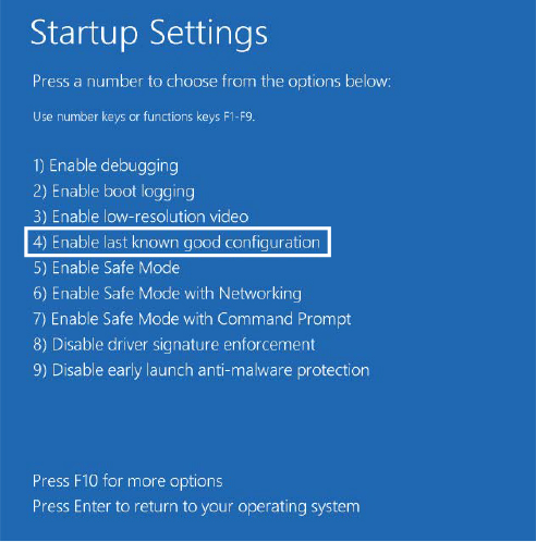
Figure 10-20 Enabling the last known good configuration.
Service failures
A service can have optional FailureActions and FailureCommand values in its registry key that the SCM records during the service’s startup. The SCM registers with the system so that the system signals the SCM when a service process exits. When a service process terminates unexpectedly, the SCM determines which services ran in the process and takes the recovery steps specified by their failure-related registry values. Additionally, services are not only limited to requesting failure actions during crashes or unexpected service termination, since other problems, such as a memory leak, could also result in service failure.
If a service enters the SERVICE_STOPPED state and the error code returned to the SCM is not ERROR_SUCCESS, the SCM checks whether the service has the FailureActionsOnNonCrashFailures flag set and performs the same recovery as if the service had crashed. To use this functionality, the service must be configured via the ChangeServiceConfig2 API or the system administrator can use the Sc.exe utility with the Failureflag parameter to set FailureActionsOnNonCrashFailures to 1. The default value being 0, the SCM will continue to honor the same behavior as on earlier versions of Windows for all other services.
Actions that a service can configure for the SCM include restarting the service, running a program, and rebooting the computer. Furthermore, a service can specify the failure actions that take place the first time the service process fails, the second time, and subsequent times, and it can indicate a delay period that the SCM waits before restarting the service if the service asks to be restarted. You can easily manage the recovery actions for a service using the Recovery tab of the service’s Properties dialog box in the Services MMC snap-in, as shown in Figure 10-21.
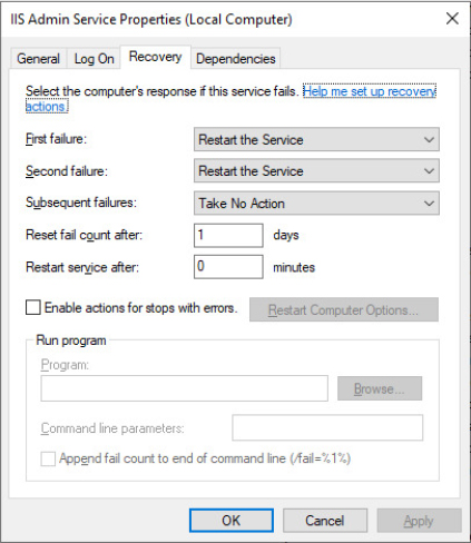
Figure 10-21 Service Recovery options.
Note that in case the next failure action is to reboot the computer, the SCM, after starting the service, marks the hosting process as critical by invoking the NtSetInformationProcess native API with the ProcessBreakOnTermination information class. A critical process, if terminated unexpectedly, crashes the system with the CRITICAL_PROCESS_DIED bugcheck (as already explained in Part 1, Chapter 2, “System architecture.”
Service shutdown
When Winlogon calls the Windows ExitWindowsEx function, ExitWindowsEx sends a message to Csrss, the Windows subsystem process, to invoke Csrss’s shutdown routine. Csrss loops through the active processes and notifies them that the system is shutting down. For every system process except the SCM, Csrss waits up to the number of seconds specified in milliseconds by HKCUControl PanelDesktopWaitToKillTimeout (which defaults to 5 seconds) for the process to exit before moving on to the next process. When Csrss encounters the SCM process, it also notifies it that the system is shutting down but employs a timeout specific to the SCM. Csrss recognizes the SCM using the process ID Csrss saved when the SCM registered with Csrss using the RegisterServicesProcess function during its initialization. The SCM’s timeout differs from that of other processes because Csrss knows that the SCM communicates with services that need to perform cleanup when they shut down, so an administrator might need to tune only the SCM’s timeout. The SCM’s timeout value in milliseconds resides in the HKLMSYSTEMCurrentControlSetControlWaitToKillServiceTimeout registry value, and it defaults to 20 seconds.
The SCM’s shutdown handler is responsible for sending shutdown notifications to all the services that requested shutdown notification when they initialized with the SCM. The SCM function ScShutdownAllServices first queries the value of the HKLMSYSTEMCurrentControlSetControlShutdownTimeout (by setting a default of 20 seconds in case the value does not exists). It then loops through the SCM services database. For each service, it unregisters eventual service triggers and determines whether the service desires to receive a shutdown notification, sending a shutdown command (SERVICE_CONTROL_SHUTDOWN) if that is the case. Note that all the notifications are sent to services in parallel by using thread pool work threads. For each service to which it sends a shutdown command, the SCM records the value of the service’s wait hint, a value that a service also specifies when it registers with the SCM. The SCM keeps track of the largest wait hint it receives (in case the maximum calculated wait hint is below the Shutdown timeout specified by the ShutdownTimeout registry value, the shutdown timeout is considered as maximum wait hint). After sending the shutdown messages, the SCM waits either until all the services it notified of shutdown exit or until the time specified by the largest wait hint passes.
While the SCM is busy telling services to shut down and waiting for them to exit, Csrss waits for the SCM to exit. If the wait hint expires without all services exiting, the SCM exits, and Csrss continues the shutdown process. In case Csrss’s wait ends without the SCM having exited (the WaitToKillServiceTimeout time expired), Csrss kills the SCM and continues the shutdown process. Thus, services that fail to shut down in a timely manner are killed. This logic lets the system shut down with the presence of services that never complete a shutdown as a result of flawed design, but it also means that services that require more than 5 seconds will not complete their shutdown operations.
Additionally, because the shutdown order is not deterministic, services that might depend on other services to shut down first (called shutdown dependencies) have no way to report this to the SCM and might never have the chance to clean up either.
To address these needs, Windows implements preshutdown notifications and shutdown ordering to combat the problems caused by these two scenarios. A preshutdown notification is sent to a service that has requested it via the SetServiceStatus API (through the SERVICE_ACCEPT_PRESHUTDOWN accepted control) using the same mechanism as shutdown notifications. Preshutdown notifications are sent before Wininit exits. The SCM generally waits for them to be acknowledged.
The idea behind these notifications is to flag services that might take a long time to clean up (such as database server services) and give them more time to complete their work. The SCM sends a progress query request and waits 10 seconds for a service to respond to this notification. If the service does not respond within this time, it is killed during the shutdown procedure; otherwise, it can keep running as long as it needs, as long as it continues to respond to the SCM.
Services that participate in the preshutdown can also specify a shutdown order with respect to other preshutdown services. Services that depend on other services to shut down first (for example, the Group Policy service needs to wait for Windows Update to finish) can specify their shutdown dependencies in the HKLMSYSTEMCurrentControlSetControlPreshutdownOrder registry value.
Shared service processes
Running every service in its own process instead of having services share a process whenever possible wastes system resources. However, sharing processes means that if any of the services in the process has a bug that causes the process to exit, all the services in that process terminate.
Of the Windows built-in services, some run in their own process and some share a process with other services. For example, the LSASS process contains security-related services—such as the Security Accounts Manager (SamSs) service, the Net Logon (Netlogon) service, the Encrypting File System (EFS) service, and the Crypto Next Generation (CNG) Key Isolation (KeyIso) service.
There is also a generic process named Service Host (SvcHost - %SystemRoot%System32Svchost.exe) to contain multiple services. Multiple instances of SvcHost run as different processes. Services that run in SvcHost processes include Telephony (TapiSrv), Remote Procedure Call (RpcSs), and Remote Access Connection Manager (RasMan). Windows implements services that run in SvcHost as DLLs and includes an ImagePath definition of the form %SystemRoot%System32svchost.exe –k netsvcs in the service’s registry key. The service’s registry key must also have a registry value named ServiceDll under a Parameters subkey that points to the service’s DLL file.
All services that share a common SvcHost process specify the same parameter (–k netsvcs in the example in the preceding paragraph) so that they have a single entry in the SCM’s image database. When the SCM encounters the first service that has a SvcHost ImagePath with a particular parameter during service startup, it creates a new image database entry and launches a SvcHost process with the parameter. The parameter specified with the -k switch is the name of the service group. The entire command line is parsed by the SCM while creating the new shared hosting process. As discussed in the “Service logon” section, in case another service in the database shares the same ImagePath value, its service SID will be added to the new hosting process’s group SIDs list.
The new SvcHost process takes the service group specified in the command line and looks for a value having the same name under HKLMSOFTWAREMicrosoftWindows NTCurrentVersionSvchost. SvcHost reads the contents of the value, interpreting it as a list of service names, and notifies the SCM that it’s hosting those services when SvcHost registers with the SCM.
When the SCM encounters another shared service (by checking the service type value) during service startup with an ImagePath matching an entry it already has in the image database, it doesn’t launch a second process but instead just sends a start command for the service to the SvcHost it already started for that ImagePath value. The existing SvcHost process reads the ServiceDll parameter in the service’s registry key, enables the new service group SID in its token, and loads the DLL into its process to start the service.
Table 10-12 lists all the default service groupings on Windows and some of the services that are registered for each of them.
Table 10-12 Major service groupings
Service Group |
Services |
Notes |
|---|---|---|
LocalService |
Network Store Interface, Windows Diagnostic Host, Windows Time, COM+ Event System, HTTP Auto-Proxy Service, Software Protection Platform UI Notification, Thread Order Service, LLDT Discovery, SSL, FDP Host, WebClient |
Services that run in the local service account and make use of the network on various ports or have no network usage at all (and hence no restrictions). |
LocalServiceAndNoImpersonation |
UPnP and SSDP, Smart Card, TPM, Font Cache, Function Discovery, AppID, qWAVE, Windows Connect Now, Media Center Extender, Adaptive Brightness |
Services that run in the local service account and make use of the network on a fixed set of ports. Services run with a write-restricted token. |
LocalServiceNetworkRestricted |
DHCP, Event Logger, Windows Audio, NetBIOS, Security Center, Parental Controls, HomeGroup Provider |
Services that run in the local service account and make use of the network on a fixed set of ports. |
LocalServiceNoNetwork |
Diagnostic Policy Engine, Base Filtering Engine, Performance Logging and Alerts, Windows Firewall, WWAN AutoConfig |
Services that run in the local service account but make no use of the network at all. Services run with a write-restricted token. |
LocalSystemNetworkRestricted |
DWM, WDI System Host, Network Connections, Distributed Link Tracking, Windows Audio Endpoint, Wired/WLAN AutoConfig, Pnp-X, HID Access, User-Mode Driver Framework Service, Superfetch, Portable Device Enumerator, HomeGroup Listener, Tablet Input, Program Compatibility, Offline Files |
Services that run in the local system account and make use of the network on a fixed set of ports. |
NetworkService |
Cryptographic Services, DHCP Client, Terminal Services, WorkStation, Network Access Protection, NLA, DNS Client, Telephony, Windows Event Collector, WinRM |
Services that run in the network service account and make use of the network on various ports (or have no enforced network restrictions). |
NetworkServiceAndNoImpersonation |
KTM for DTC |
Services that run in the network service account and make use of the network on a fixed set of ports. Services run with a write-restricted token. |
NetworkServiceNetworkRestricted |
IPSec Policy Agent |
Services that run in the network service account and make use of the network on a fixed set of ports. |
Svchost service splitting
As discussed in the previous section, running a service in a shared host process saves system resources but has the big drawback that a single unhandled error in a service obliges all the other services shared in the host process to be killed. To overcome this problem, Windows 10 Creators Update (RS2) has introduced the Svchost Service splitting feature.
When the SCM starts, it reads three values from the registry representing the services global commit limits (divided in: low, medium, and hard caps). These values are used by the SCM to send “low resources” messages in case the system runs under low-memory conditions. It then reads the Svchost Service split threshold value from the HKLMSYSTEMCurrentControlSetControlSvcHostSplitThresholdInKB registry value. The value contains the minimum amount of system physical memory (expressed in KB) needed to enable Svchost Service splitting (the default value is 3.5 GB on client systems and around 3.7 GB on server systems). The SCM then obtains the value of the total system physical memory using the GlobalMemoryStatusEx API and compares it with the threshold previously read from the registry. If the total physical memory is above the threshold, it enables Svchost service splitting (by setting an internal global variable).
Svchost service splitting, when active, modifies the behavior in which SCM starts the host Svchost process of shared services. As already discussed in the “Service start” section earlier in this chapter, the SCM does not search for an existing image record in its database if service splitting is allowed for a service. This means that, even though a service is marked as sharable, it is started using its private hosting process (and its type is changed to SERVICE_WIN32_OWN_PROCESS). Service splitting is allowed only if the following conditions apply:
■ Svchost Service splitting is globally enabled.
■ The service is not marked as critical. A service is marked as critical if its next recovery action specifies to reboot the machine (as discussed previously in the “Service failures” section).
■ The service host process name is Svchost.exe.
■ Service splitting is not explicitly disabled for the service through the SvcHostSplitDisable registry value in the service control key.
Memory manager’s technologies like Memory Compression and Combining help in saving as much of the system working set as possible. This explains one of the motivations behind the enablement of Svchost service splitting. Even though many new processes are created in the system, the memory manager assures that all the physical pages of the hosting processes remain shared and consume as little system resources as possible. Memory combining, compression, and memory sharing are explained in detail in Chapter 5 of Part 1.
Service tags
One of the disadvantages of using service-hosting processes is that accounting for CPU time and usage, as well as for the usage of resources by a specific service is much harder because each service is sharing the memory address space, handle table, and per-process CPU accounting numbers with the other services that are part of the same service group. Although there is always a thread inside the service-hosting process that belongs to a certain service, this association might not always be easy to make. For example, the service might be using worker threads to perform its operation, or perhaps the start address and stack of the thread do not reveal the service’s DLL name, making it hard to figure out what kind of work a thread might be doing and to which service it might belong.
Windows implements a service attribute called the service tag (not to be confused with the driver tag), which the SCM generates by calling ScGenerateServiceTag when a service is created or when the service database is generated during system boot. The attribute is simply an index identifying the service. The service tag is stored in the SubProcessTag field of the thread environment block (TEB) of each thread (see Chapter 3 of Part 1 for more information on the TEB) and is propagated across all threads that a main service thread creates (except threads created indirectly by thread-pool APIs).
Although the service tag is kept internal to the SCM, several Windows utilities, like Netstat.exe (a utility you can use for displaying which programs have opened which ports on the network), use undocumented APIs to query service tags and map them to service names. Another tool you can use to look at service tags is ScTagQuery from Winsider Seminars & Solutions Inc. (www.winsiderss.com/tools/sctagquery/sctagquery.htm). It can query the SCM for the mappings of every service tag and display them either systemwide or per-process. It can also show you to which services all the threads inside a service-hosting process belong. (This is conditional on those threads having a proper service tag associated with them.) This way, if you have a runaway service consuming lots of CPU time, you can identify the culprit service in case the thread start address or stack does not have an obvious service DLL associated with it.
User services
As discussed in the “Running services in alternate accounts” section, a service can be launched using the account of a local system user. A service configured in that way is always loaded using the specified user account, regardless of whether the user is currently logged on. This could represent a limitation in multiuser environments, where a service should be executed with the access token of the currently logged-on user. Furthermore, it can expose the user account at risk because malicious users can potentially inject into the service process and use its token to access resources they are not supposed to (being able also to authenticate on the network).
Available from Windows 10 Creators Update (RS2), User Services allow a service to run with the token of the currently logged-on user. User services can be run in their own process or can share a process with one or more other services running in the same logged-on user account as for standard services. They are started when a user performs an interactive logon and stopped when the user logs off. The SCM internally supports two additional type flags—SERVICE_USER_SERVICE (64) and SERVICE_USERSERVICE_INSTANCE (128)—which identify a user service template and a user service instance.
One of the states of the Winlogon finite-state machine (see Chapter 12 for details on Winlogon and the boot process) is executed when an interactive logon has been initiated. The state creates the new user’s logon session, window station, desktop, and environment; maps the HKEY_CURRENT_USER registry hive; and notifies the logon subscribers (LogonUI and User Manager). The User Manager service (Usermgr.dll) through RPC is able to call into the SCM for delivering the WTS_SESSION_LOGON session event.
The SCM processes the message through the ScCreateUserServicesForUser function, which calls back into the User Manager for obtaining the currently logged-on user’s token. It then queries the list of user template services from the SCM database and, for each of them, generates the new name of the user instance service.
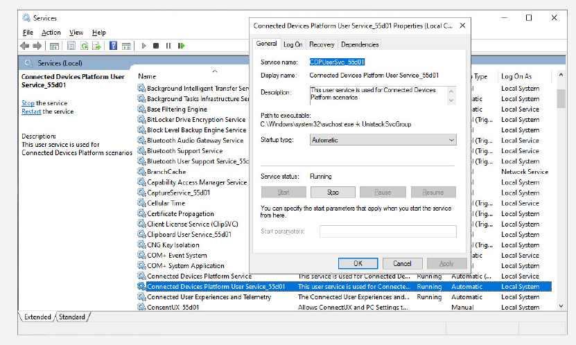
!process <ServicePid> 1
Kd: 0> !process 0n5936 1
Searching for Process with Cid == 1730
PROCESS ffffe10646205080
    SessionId: 2  Cid: 1730    Peb: 81ebbd1000  ParentCid: 0344
    DirBase: 8fe39002  ObjectTable: ffffa387c2826340  HandleCount: 313.
    Image: svchost.exe
    VadRoot ffffe1064629c340 Vads 108 Clone 0 Private 962. Modified 214. Locked 0.
    DeviceMap ffffa387be1341a0
    Token                             ffffa387c2bdc060
    ElapsedTime                       00:35:29.441
    ...
    <Output omitted for space reasons>
0: kd> !token ffffa387c2bdc060
_TOKEN 0xffffa387c2bdc060
TS Session ID: 0x2
User: S-1-5-21-725390342-1520761410-3673083892-1001
User Groups:
 00 S-1-5-21-725390342-1520761410-3673083892-513
    Attributes - Mandatory Default Enabled

... <Output omitted for space reason> ...

OriginatingLogonSession: 3e7
PackageSid: (null)
CapabilityCount: 0      Capabilities: 0x0000000000000000
LowboxNumberEntry: 0x0000000000000000
Security Attributes:
 00 Claim Name   : WIN://SCMUserService
    Claim Flags: 0x40 - UNKNOWN
    Value Type   : CLAIM_SECURITY_ATTRIBUTE_TYPE_UINT64
    Value Count: 1
    Value[0]   : 0
 01 Claim Name   : TSA://ProcUnique
    Claim Flags: 0x41 - UNKNOWN
    Value Type   : CLAIM_SECURITY_ATTRIBUTE_TYPE_UINT64
    Value Count: 2
    Value[0]   : 102
    Value[1]   : 352550
Figure 10-22 shows an example of a user service instance, the Clipboard User Service, which is run using the token of the currently logged-on user. The generated context ID for session 1 is 0x3a182, as shown by the User Manager volatile registry key (see the previous experiment for details). The SCM then calls ScCreateService, which creates a service record in the SCM database. The new service record represents a new user service instance and is saved in the registry as for normal services. The service security descriptor, all the dependent services, and the triggers information are copied from the user service template to the new user instance service.
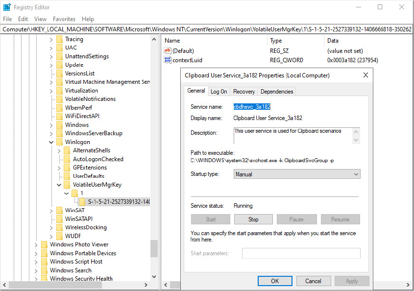
Figure 10-22 The Clipboard User Service instance running in the context ID 0x3a182.
The SCM registers the eventual service triggers (see the “Triggered-start services” section earlier in this chapter for details) and then starts the service (if its start type is set to SERVICE_AUTO_START). As discussed in the “Service logon” section, when SCM starts a process hosting a user service, it assigns the token of the current logged-on user and the WIN://ScmUserService security attribute used by the SCM to recognize that the process is really hosting a service. Figure 10-23 shows that, after a user has logged in to the system, both the instance and template subkeys are stored in the root services key representing the same user service. The instance subkey is deleted on user logoff and ignored if it’s still present at system startup time.
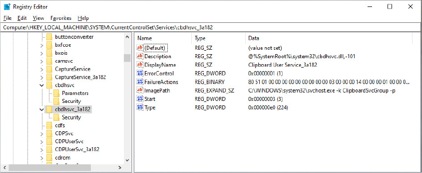
Figure 10-23 User service instance and template registry keys.
Packaged services
As briefly introduced in the “Service logon” section, since Windows 10 Anniversary Update (RS1), the Service Control Manager has supported packaged services. A packaged service is identified through the SERVICE_PKG_SERVICE (512) flag set in its service type. Packaged services have been designed mainly to support standard Win32 desktop applications (which may run with an associated service) converted to the new Modern Application Model. The Desktop App Converter is indeed able to convert a Win32 application to a Centennial app, which runs in a lightweight container, internally called Helium. More details on the Modern Application Model are available in the “Packaged application” section of Chapter 8.
When starting a packaged service, the SCM reads the package information from the registry, and, as for standard Centennial applications, calls into the AppInfo service. The latter verifies that the package information exists in the state repository and the integrity of all the application package files. It then stamps the new service’s host process token with the correct security attributes. The process is then launched in a suspended state using CreateProcessAsUser API (including the Package Full Name attribute) and a Helium container is created, which will apply registry redirection and Virtual File System (VFS) as for regular Centennial applications.
Protected services
Chapter 3 of Part 1 described in detail the architecture of protected processes and protected processes light (PPL). The Windows 8.1 Service Control Manager supports protected services. At the time of this writing, a service can have four levels of protection: Windows, Windows light, Antimalware light, and App. A service control program can specify the protection of a service using the ChangeServiceConfig2 API (with the SERVICE_CONFIG_LAUNCH_ PROTECTED information level). A service’s main executable (or library in the case of shared services) must be signed properly for running as a protected service, following the same rules as for protected processes (which means that the system checks the digital signature’s EKU and root certificate and generates a maximum signer level, as explained in Chapter 3 of Part 1).
A service’s hosting process launched as protected guarantees a certain kind of protection with respect to other nonprotected processes. They can’t acquire some access rights while trying to access a protected service’s hosting process, depending on the protection level. (The mechanism is identical to standard protected processes. A classic example is a nonprotected process not being able to inject any kind of code in a protected service.)
Even processes launched under the SYSTEM account can’t access a protected process. However, the SCM should be fully able to access a protected service’s hosting process. So, Wininit.exe launches the SCM by specifying the maximum user-mode protection level: WinTcb Light. Figure 10-24 shows the digital signature of the SCM main executable, services.exe, which includes the Windows TCB Component EKU (1.3.6.1.4.1.311.10.3.23).
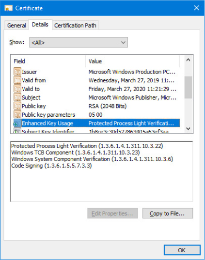
Figure 10-24 The Service Control Manager main executable (service.exe) digital certificate.
The second part of protection is brought by the Service Control Manager. While a client requests an action to be performed on a protected service, the SCM calls the ScCheckServiceProtectedProcess routine with the goal to check whether the caller has enough access rights to perform the requested action on the service. Table 10-13 lists the denied operations when requested by a nonprotected process on a protected service.
Table 10-13 List of denied operations while requested from nonprotected client
Involved API Name |
Operation |
Description |
|---|---|---|
ChangeServiceConfig[2] |
Change Service Configuration |
Any change of configuration to a protected service is denied. |
SetServiceObjectSecurity |
Set a new security descriptor to a service |
Application of a new security descriptor to a protected service is denied. (It could lower the service attack surface.) |
DeleteService |
Delete a Service |
Nonprotected process can’t delete a protected service. |
ControlService |
Send a control code to a service |
Only service-defined control code and SERVICE_CONTROL_INTERROGATE are allowed for nonprotected callers. SERVICE_CONTROL_STOP is allowed for any protection level except for Antimalware. |
The ScCheckServiceProtectedProcess function looks up the service record from the caller-specified service handle and, in case the service is not protected, always grants access. Otherwise, it impersonates the client process token, obtains its process protection level, and implements the following rules:
■ If the request is a STOP control request and the target service is not protected at Antimalware level, grant the access (Antimalware protected services are not stoppable by non-protected processes).
■ In case the TrustedInstaller service SID is present in the client’s token groups or is set as the token user, the SCM grants access regarding the client’s process protection.
■ Otherwise, it calls RtlTestProtectedAccess, which performs the same checks implemented for protected processes. The access is granted only if the client process has a compatible protection level with the target service. For example, a Windows protected process can always operate on all protected service levels, while an antimalware PPL can only operate on Antimalware and app protected services.
Noteworthy is that the last check described is not executed for any client process running with the TrustedInstaller virtual service account. This is by design. When Windows Update installs an update, it should be able to start, stop, and control any kind of service without requiring itself to be signed with a strong digital signature (which could expose Windows Update to an undesired attack surface).
Task scheduling and UBPM
Various Windows components have traditionally been in charge of managing hosted or background tasks as the operating system has increased in complexity in features, from the Service Control Manager, described earlier, to the DCOM Server Launcher and the WMI Provider—all of which are also responsible for the execution of out-of-process, hosted code. Although modern versions of Windows use the Background Broker Infrastructure to manage the majority of background tasks of modern applications (see Chapter 8 for more details), the Task Scheduler is still the main component that manages Win32 tasks. Windows implements a Unified Background Process Manager (UBPM), which handles tasks managed by the Task Scheduler.
The Task Scheduler service (Schedule) is implemented in the Schedsvc.dll library and started in a shared Svchost process. The Task Scheduler service maintains the tasks database and hosts UBPM, which starts and stops tasks and manages their actions and triggers. UBPM uses the services provided by the Desktop Activity Broker (DAB), the System Events Broker (SEB), and the Resource Manager for receiving notification when tasks’ triggers are generated. (DAB and SEB are both hosted in the System Events Broker service, whereas Resource Manager is hosted in the Broker Infrastructure service.) Both the Task Scheduler and UBPM provide public interfaces exposed over RPC. External applications can use COM objects to attach to those interfaces and interact with regular Win32 tasks.
The Task Scheduler
The Task Scheduler implements the task store, which provides storage for each task. It also hosts the Scheduler idle service, which is able to detect when the system enters or exits the idle state, and the Event trap provider, which helps the Task Scheduler to launch a task upon a change in the machine state and provides an internal event log triggering system. The Task Scheduler also includes another component, the UBPM Proxy, which collects all the tasks’ actions and triggers, converts their descriptors to a format that UBPM can understand, and sends them to UBPM.
An overview of the Task Scheduler architecture is shown in Figure 10-25. As highlighted by the picture, the Task Scheduler works deeply in collaboration with UBPM (both components run in the Task Scheduler service, which is hosted by a shared Svchost.exe process.) UBPM manages the task’s states and receives notification from SEB, DAB, and Resource Manager through WNF states.
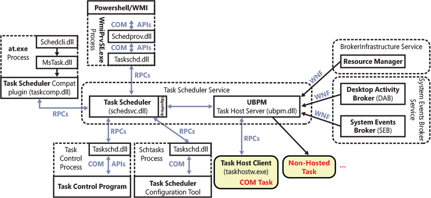
Figure 10-25 The Task Scheduler architecture.
The Task Scheduler has the important job of exposing the server part of the COM Task Scheduler APIs. When a Task Control program invokes one of those APIs, the Task Scheduler COM API library (Taskschd.dll) is loaded in the address space of the application by the COM engine. The library requests services on behalf of the Task Control Program to the Task Scheduler through RPC interfaces.
In a similar way, the Task Scheduler WMI provider (Schedprov.dll) implements COM classes and methods able to communicate with the Task Scheduler COM API library. Its WMI classes, properties, and events can be called from Windows PowerShell through the ScheduledTasks cmdlet (documented at https://docs.microsoft.com/en-us/powershell/module/scheduledtasks/). Note that the Task Scheduler includes a Compatibility plug-in, which allows legacy applications, like the AT command, to work with the Task Scheduler. In the May 2019 Update edition of Windows 10 (19H1), the AT tool has been declared deprecated, and you should instead use schtasks.exe.
Initialization
When started by the Service Control Manager, the Task Scheduler service begins its initialization procedure. It starts by registering its manifest-based ETW event provider (that has the DE7B24EA-73C8-4A09-985D-5BDADCFA9017 global unique ID). All the events generated by the Task Scheduler are consumed by UBPM. It then initializes the Credential store, which is a component used to securely access the user credentials stored by the Credential Manager and the Task store. The latter checks that all the XML task descriptors located in the Task store’s secondary shadow copy (maintained for compatibility reasons and usually located in %SystemRoot%System32Tasks path) are in sync with the task descriptors located in the Task store cache. The Task store cache is represented by multiple registry keys, with the root being HKLMSOFTWAREMicrosoftWindows NTCurrentVersionScheduleTaskCache.
The next step in the Task Scheduler initialization is to initialize UBPM. The Task Scheduler service uses the UbpmInitialize API exported from UBPM.dll for starting the core components of UBPM. The function registers an ETW consumer of the Task Scheduler’s event provider and connects to the Resource Manager. The Resource Manager is a component loaded by the Process State Manager (Psmsrv.dll, in the context of the Broker Infrastructure service), which drives resource-wise policies based on the machine state and global resource usage. Resource Manager helps UBPM to manage maintenance tasks. Those types of tasks run only in particular system states, like when the workstation CPU usage is low, when game mode is off, the user is not physically present, and so on. UBPM initialization code then retrieves the WNF state names representing the task’s conditions from the System Event Broker: AC power, Idle Workstation, IP address or network available, Workstation switching to Battery power. (Those conditions are visible in the Conditions sheet of the Create Task dialog box of the Task Scheduler MMC plug-in.)
UBPM initializes its internal thread pool worker threads, obtains system power capabilities, reads a list of the maintenance and critical task actions (from the HKLMSystemCurrentControlSetControlUbpm registry key and group policy settings) and subscribes to system power settings notifications (in that way UBPM knows when the system changes its power state).
The execution control returns to the Task Scheduler, which finally registers the global RPC interfaces of both itself and UBPM. Those interfaces are used by the Task Scheduler API client-side DLL (Taskschd.dll) to provide a way for client processes to interact via the Task Scheduler via the Task Scheduler COM interfaces, which are documented at https://docs.microsoft.com/en-us/windows/win32/api/taskschd/.
After the initialization is complete, the Task store enumerates all the tasks that are installed in the system and starts each of them. Tasks are stored in the cache in four groups: Boot, logon, plain, and Maintenance task. Each group has an associated subkey, called Index Group Tasks key, located in the Task store’s root registry key (HKLM SOFTWAREMicrosoftWindows NTCurrentVersionScheduleTaskCache, as introduced previously). Inside each Index Tasks group key is one subkey per each task, identified through a global unique identifier (GUID). The Task Scheduler enumerates the names of all the group’s subkeys, and, for each of them, opens the relative Task’s master key, which is located in the Tasks subkey of the Task store’s root registry key. Figure 10-26 shows a sample boot task, which has the {0C7D8A27-9B28-49F1-979C-AD37C4D290B1} GUID. The task GUID is listed in the figure as one of the first entries in the Boot index group key. The figure also shows the master Task key, which stores binary data in the registry to entirely describe the task.
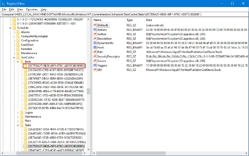
Figure 10-26 A boot task master key.
The task’s master key contains all the information that describes the task. Two properties of the task are the most important: Triggers, which describe the conditions that will trigger the task, and Actions, which describe what happen when the task is executed. Both properties are stored in binary registry values (named “Triggers” and “Actions,”, as shown in Figure 10-26). The Task Scheduler first reads the hash of the entire task descriptor (stored in the Hash registry value); then it reads all the task’s configuration data and the binary data for triggers and actions. After parsing this data, it adds each identified trigger and action descriptor to an internal list.
The Task Scheduler then recalculates the SHA256 hash of the new task descriptor (which includes all the data read from the registry) and compares it with the expected value. If the two hashes do not match, the Task Scheduler opens the XML file associated with the task contained in the store’s shadow copy (the %SystemRoot%System32Tasks folder), parses its data and recalculates a new hash, and finally replaces the task descriptor in the registry. Indeed, tasks can be described by binary data included in the registry and also by an XML file, which adhere to a well-defined schema, documented at https://docs.microsoft.com/en-us/windows/win32/taskschd/task-scheduler-schema.
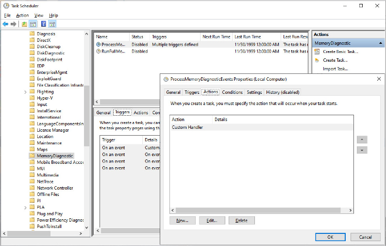
schtasks /query /tn "MicrosoftWindowsMemoryDiagnosticProcessMemoryDiagnosticEvents" /xml
<?xml version="1.0" encoding="UTF-16"?>
<Task xmlns="http://schemas.microsoft.com/windows/2004/02/mit/task">
<RegistrationInfo>
<Version>1.0</Version>
<SecurityDescriptor>D:P(A;;FA;;;BA)(A;;FA;;;SY)(A;;FR;;;AU)</SecurityDescriptor>
<Author>$(@%SystemRoot%system32MemoryDiagnostic.dll,-600)</Author>
<Description>$(@%SystemRoot%system32MemoryDiagnostic.dll,-603)</Description>
<URI>MicrosoftWindowsMemoryDiagnosticProcessMemoryDiagnosticEvents</URI>
</RegistrationInfo>
<Principals>
<Principal id="LocalAdmin">
<GroupId>S-1-5-32-544</GroupId>
<RunLevel>HighestAvailable</RunLevel>
</Principal>
</Principals>
<Settings>
<AllowHardTerminate>false</AllowHardTerminate>
<DisallowStartIfOnBatteries>true</DisallowStartIfOnBatteries>
<StopIfGoingOnBatteries>true</StopIfGoingOnBatteries>
<Enabled>false</Enabled>
<ExecutionTimeLimit>PT2H</ExecutionTimeLimit>
<Hidden>true</Hidden>
<MultipleInstancesPolicy>IgnoreNew</MultipleInstancesPolicy>
<StartWhenAvailable>true</StartWhenAvailable>
<RunOnlyIfIdle>true</RunOnlyIfIdle>
<IdleSettings>
<StopOnIdleEnd>true</StopOnIdleEnd>
<RestartOnIdle>true</RestartOnIdle>
</IdleSettings>
<UseUnifiedSchedulingEngine>true</UseUnifiedSchedulingEngine>
</Settings>
<Triggers>
<EventTrigger>
<Subscription><QueryList><Query Id="0" Path="System"><Select Path="System">*[System[Provider[@Name=’Microsoft-Windows-WER-SystemErrorReporting’] and (EventID=1000 or EventID=1001 or EventID=1006)]]</Select></Query></QueryList></Subscription>
</EventTrigger>
. . . [cut for space reasons] . . .
</Triggers>
<Actions Context="LocalAdmin">
<ComHandler>
<ClassId>{8168E74A-B39F-46D8-ADCD-7BED477B80A3}</ClassId>
<Data><![CDATA[Event]]></Data>
</ComHandler>
</Actions>
</Task>

Enabled tasks should be registered with UBPM. The Task Scheduler calls the RegisterTask function of the Ubpm Proxy, which first connects to the Credential store, for retrieving the credential used to start the task, and then processes the list of all actions and triggers (stored in an internal list), converting them in a format that UBPM can understand. Finally, it calls the UbpmTriggerConsumerRegister API exported from UBPM.dll. The task is ready to be executed when the right conditions are verified.
Unified Background Process Manager (UBPM)
Traditionally, UBPM was mainly responsible in managing tasks’ life cycles and states (start, stop, enable/disable, and so on) and to provide notification and triggers support. Windows 8.1 introduced the Broker Infrastructure and moved all the triggers and notifications management to different brokers that can be used by both Modern and standard Win32 applications. Thus, in Windows 10, UBPM acts as a proxy for standard Win32 Tasks’ triggers and translates the trigger consumers request to the correct broker. UBPM is still responsible for providing COM APIs available to applications for the following:
■ Registering and unregistering a trigger consumer, as well as opening and closing a handle to one
■ Generating a notification or a trigger
■ Sending a command to a trigger provider
Similar to the Task Scheduler’s architecture, UBPM is composed of various internal components: Task Host server and client, COM-based Task Host library, and Event Manager.
Task host server
When one of the System brokers raises an event registered by a UBPM trigger consumer (by publishing a WNF state change), the UbpmTriggerArrived callback function is executed. UBPM searches the internal list of a registered task’s triggers (based on the WNF state name) and, when it finds the correct one, processes the task’s actions. At the time of this writing, only the Launch Executable action is supported. This action supports both hosted and nonhosted executables. Nonhosted executables are regular Win32 executables that do not directly interact with UBPM; hosted executables are COM classes that directly interact with UBPM and need to be hosted by a task host client process. After a host-based executable (taskhostw.exe) is launched, it can host different tasks, depending on its associated token. (Host-based executables are very similar to shared Svchost services.)
Like SCM, UBPM supports different types of logon security tokens for task’s host processes. The UbpmTokenGetTokenForTask function is able to create a new token based on the account information stored in the task descriptor. The security token generated by UBPM for a task can have one of the following owners: a registered user account, Virtual Service account, Network Service account, or Local Service account. Unlike SCM, UBPM fully supports Interactive tokens. UBPM uses services exposed by the User Manager (Usermgr.dll) to enumerate the currently active interactive sessions. For each session, it compares the User SID specified in the task’s descriptor with the owner of the interactive session. If the two match, UBPM duplicates the token attached to the interactive session and uses it to log on the new executable. As a result, interactive tasks can run only with a standard user account. (Noninteractive tasks can run with all the account types listed previously.)
After the token has been generated, UBPM starts the task’s host process. In case the task is a hosted COM task, the UbpmFindHost function searches inside an internal list of Taskhostw.exe (task host client) process instances. If it finds a process that runs with the same security context of the new task, it simply sends a Start Task command (which includes the COM task’s name and CLSID) through the task host local RPC connection and waits for the first response. The task host client process and UBPM are connected through a static RPC channel (named ubpmtaskhostchannel) and use a connection protocol similar to the one implemented in the SCM.
If a compatible client process instance has not been found, or if the task’s host process is a regular non-COM executable, UBPM builds a new environment block, parses the command line, and creates a new process in a suspended state using the CreateProcessAsUser API. UBPM runs each task’s host process in a Job object, which allows it to quickly set the state of multiple tasks and fine-tune the resources allocated for background tasks. UBPM searches inside an internal list for Job objects containing host processes belonging to the same session ID and the same type of tasks (regular, critical, COM-based, or non-hosted). If it finds a compatible Job, it simply assigns the new process to the Job (by using the AssignProcessToJobObject API). Otherwise, it creates a new one and adds it to its internal list.
After the Job object has been created, the task is finally ready to be started: the initial process’s thread is resumed. For COM-hosted tasks, UBPM waits for the initial contact from the task host client (performed when the client wants to open a RPC communication channel with UBPM, similar to the way in which Service control applications open a channel to the SCM) and sends the Start Task command. UBPM finally registers a wait callback on the task’s host process, which allow it to detect when a task host’s process terminates unexpectedly.
Task Host client
The Task Host client process receives commands from UBPM (Task Host Server) living in the Task Scheduler service. At initialization time, it opens the local RPC interface that was created by UBPM during its initialization and loops forever, waiting for commands to come through the channel. Four commands are currently supported, which are sent over the TaskHostSendResponseReceiveCommand RPC API:
■ Stopping the host
■ Starting a task
■ Stopping a task
■ Terminating a task
All task-based commands are internally implemented by a generic COM task library, and they essentially result in the creation and destruction of COM components. In particular, hosted tasks are COM objects that inherit from the ITaskHandler interface. The latter exposes only four required methods, which correspond to the different task’s state transitions: Start, Stop, Pause, and Resume. When UBPM sends the command to start a task to its client host process, the latter (Taskhostw.exe) creates a new thread for the task. The new task worker thread uses the CoCreateInstance function to create an instance of the ITaskHandler COM object representing the task and calls its Start method. UBPM knows exactly which CLSID (class unique ID) identifies a particular task: The task’s CLSID is stored by the Task store in the task’s configuration and is specified at task registration time. Additionally, hosted tasks use the functions exposed by the ITaskHandlerStatus COM interface to notify UBPM of their current execution state. The interface uses RPCs to call UbpmReportTaskStatus and report the new state back to UBPM.
You need to set up Windbg as the default post-mortem debugger. (You can skip this step if you have connected a kernel debugger to the target system.) To do that, open an administrative command prompt and type the following commands:
cd "C:Program Files (x86)Windows Kits10Debuggersx64"
windbg.exe /I
Note that C:Program Files (x86)Windows Kits10Debuggersx64 is the path of the Debugging tools, which can change depending on the debugger’s version and the setup program.
Windbg should run and show the following message, confirming the success of the operation:
After you click on the OK button, WinDbg should close automatically.
Open the Task Scheduler applet (by typing taskschd.msc in the command prompt).
Note that unless you have a kernel debugger attached, you can’t enable the initial task’s breakpoint on noninteractive tasks; otherwise, you won’t be able to interact with the debugger window, which will be spawned in another noninteractive session.
Looking at the various tasks (refer to the previous experiment, “Explore a task’s XML descriptor” for further details), you should find an interactive COM task (named CacheTask) under the MicrosoftWindowsWininet path. Remember that the task’s Actions page should show Custom Handler; otherwise the task is not COM task.
Open the Registry Editor (by typing regedit in the command prompt window) and navigate to the following registry key: HKLMSOFTWAREMicrosoftWindows NTCurrentVersionSchedule.
Right-click the Schedule key and create a new registry value by selecting Multi-String Value from the New menu.
Name the new registry value as EnableDebuggerBreakForTaskStart. To enable the initial task breakpoint, you should insert the full path of the task. In this case, the full path is MicrosoftWindowsWininetCacheTask. In the previous experiment, the task path has been referred as the task’s URI.
Close the Registry Editor and switch back to the Task Scheduler.
Right-click the CacheTask task and select Run.
If you have configured everything correctly, a new WinDbg window should appear.
Configure the symbols used by the debugger by selecting the Symbol File Path item from the File menu and by inserting a valid path to the Windows symbol server (see https://docs.microsoft.com/en-us/windows-hardware/drivers/debugger/microsoft-public-symbols for more details).
You should be able to peek at the call stack of the Taskhostw.exe process just before it was interrupted using the k command:
0:000> k
 # Child-SP          RetAddr           Call Site
00 000000a7`01a7f610 00007ff6`0b0337a8 taskhostw!ComTaskMgrBase::[ComTaskMgr]::StartComTask+0x2c4
01 000000a7`01a7f960 00007ff6`0b033621 taskhostw!StartComTask+0x58
02 000000a7`01a7f9d0 00007ff6`0b033191 taskhostw!UbpmTaskHostWaitForCommands+0x2d1
3 000000a7`01a7fb00 00007ff6`0b035659 taskhostw!wWinMain+0xc1
04 000000a7`01a7fb60 00007ffa`39487bd4 taskhostw!__wmainCRTStartup+0x1c9
05 000000a7`01a7fc20 00007ffa`39aeced1 KERNEL32!BaseThreadInitThunk+0x14
06 000000a7`01a7fc50 00000000`00000000 ntdll!RtlUserThreadStart+0x21
The stack shows that the task host client has just been spawned by UBPM and has received the Start command requesting to start a task.
In the Windbg console, insert the ~. command and press Enter. Note the current executing thread ID.
You should now put a breakpoint on the CoCreateInstance COM API and resume the execution, using the following commands:
bp combase!CoCreateInstance
g
After the debugger breaks, again insert the ~. command in the Windbg console, press Enter, and note that the thread ID has completely changed.
This demonstrates that the task host client has created a new thread for executing the task entry point. The documented CoCreateInstance function is used for creating a single COM object of the class associated with a particular CLSID, specified as a parameter. Two GUIDs are interesting for this experiment: the GUID of the COM class that represents the Task and the interface ID of the interface implemented by the COM object.
In 64-bit systems, the calling convention defines that the first four function parameters are passed through registers, so it is easy to extract those GUIDs:
0:004> dt combase!CLSID @rcx
 {0358b920-0ac7-461f-98f4-58e32cd89148}
   +0x000 Data1            : 0x358b920
   +0x004 Data2            : 0xac7
   +0x006 Data3            : 0x461f
   +0x008 Data4            : [8] "???"
0:004> dt combase!IID @r9
 {839d7762-5121-4009-9234-4f0d19394f04}
   +0x000 Data1            : 0x839d7762
   +0x004 Data2            : 0x5121
   +0x006 Data3            : 0x4009
   +0x008 Data4            : [8] "???"
Task Scheduler COM interfaces
As we have discussed in the previous section, a COM task should adhere to a well-defined interface, which is used by UBPM to manage the state transition of the task. While UBPM decides when to start the task and manages all of its state, all the other interfaces used to register, remove, or just manually start and stop a task are implemented by the Task Scheduler in its client-side DLL (Taskschd.dll).
ITaskService is the central interface by which clients can connect to the Task Scheduler and perform multiple operations, like enumerate registered tasks; get an instance of the Task store (represented by the ITaskFolder COM interface); and enable, disable, delete, or register a task and all of its associated triggers and actions (by using the ITaskDefinition COM interface). When a client application invokes for the first time a Task Scheduler APIs through COM, the system loads the Task Scheduler client-side DLL (Taskschd.dll) into the client process’s address space (as dictated by the COM contract: Task Scheduler COM objects live in an in-proc COM server). The COM APIs are implemented by routing requests through RPC calls into the Task Scheduler service, which processes each request and forwards it to UBPM if needed. The Task Scheduler COM architecture allows users to interact with it via scripting languages like PowerShell (through the ScheduledTasks cmdlet) or VBScript.
Windows Management Instrumentation
Windows Management Instrumentation (WMI) is an implementation of Web-Based Enterprise Management (WBEM), a standard that the Distributed Management Task Force (DMTF—an industry consortium) defines. The WBEM standard encompasses the design of an extensible enterprise data-collection and data-management facility that has the flexibility and extensibility required to manage local and remote systems that comprise arbitrary components.
WMI architecture
WMI consists of four main components, as shown in Figure 10-27: management applications, WMI infrastructure, providers, and managed objects. Management applications are Windows applications that access and display or process data about managed objects. A simple example of a management application is a performance tool replacement that relies on WMI rather than the Performance API to obtain performance information. A more complex example is an enterprise-management tool that lets administrators perform automated inventories of the software and hardware configuration of every computer in their enterprise.
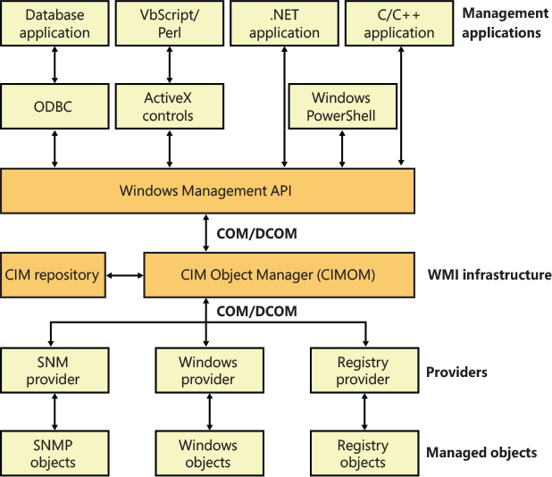
Figure 10-27 WMI architecture.
Developers typically must target management applications to collect data from and manage specific objects. An object might represent one component, such as a network adapter device, or a collection of components, such as a computer. (The computer object might contain the network adapter object.) Providers need to define and export the representation of the objects that management applications are interested in. For example, the vendor of a network adapter might want to add adapter-specific properties to the network adapter WMI support that Windows includes, querying and setting the adapter’s state and behavior as the management applications direct. In some cases (for example, for device drivers), Microsoft supplies a provider that has its own API to help developers leverage the provider’s implementation for their own managed objects with minimal coding effort.
The WMI infrastructure, the heart of which is the Common Information Model (CIM) Object Manager (CIMOM), is the glue that binds management applications and providers. (CIM is described later in this chapter.) The infrastructure also serves as the object-class store and, in many cases, as the storage manager for persistent object properties. WMI implements the store, or repository, as an on-disk database named the CIMOM Object Repository. As part of its infrastructure, WMI supports several APIs through which management applications access object data and providers supply data and class definitions.
Windows programs and scripts (such as Windows PowerShell) use the WMI COM API, the primary management API, to directly interact with WMI. Other APIs layer on top of the COM API and include an Open Database Connectivity (ODBC) adapter for the Microsoft Access database application. A database developer uses the WMI ODBC adapter to embed references to object data in the developer’s database. Then the developer can easily generate reports with database queries that contain WMI-based data. WMI ActiveX controls support another layered API. Web developers use the ActiveX controls to construct web-based interfaces to WMI data. Another management API is the WMI scripting API, for use in script-based applications (like Visual Basic Scripting Edition). WMI scripting support exists for all Microsoft programming language technologies.
Because WMI COM interfaces are for management applications, they constitute the primary API for providers. However, unlike management applications, which are COM clients, providers are COM or Distributed COM (DCOM) servers (that is, the providers implement COM objects that WMI interacts with). Possible embodiments of a WMI provider include DLLs that load into a WMI’s manager process or stand-alone Windows applications or Windows services. Microsoft includes a number of built-in providers that present data from well-known sources, such as the Performance API, the registry, the Event Manager, Active Directory, SNMP, and modern device drivers. The WMI SDK lets developers develop third-party WMI providers.
WMI providers
At the core of WBEM is the DMTF-designed CIM specification. The CIM specifies how management systems represent, from a systems management perspective, anything from a computer to an application or device on a computer. Provider developers use the CIM to represent the components that make up the parts of an application for which the developers want to enable management. Developers use the Managed Object Format (MOF) language to implement a CIM representation.
In addition to defining classes that represent objects, a provider must interface WMI to the objects. WMI classifies providers according to the interface features the providers supply. Table 10-14 lists WMI provider classifications. Note that a provider can implement one or more features; therefore, a provider can be, for example, both a class and an event provider. To clarify the feature definitions in Table 10-14, let’s look at a provider that implements several of those features. The Event Log provider supports several objects, including an Event Log Computer, an Event Log Record, and an Event Log File. The Event Log is an Instance provider because it can define multiple instances for several of its classes. One class for which the Event Log provider defines multiple instances is the Event Log File class (Win32_NTEventlogFile); the Event Log provider defines an instance of this class for each of the system’s event logs (that is, System Event Log, Application Event Log, and Security Event Log).
Table 10-14 Provider classifications
Classification |
Description |
|---|---|
Class |
Can supply, modify, delete, and enumerate a provider-specific class. It can also support query processing. Active Directory is a rare example of a service that is a class provider. |
Instance |
Can supply, modify, delete, and enumerate instances of system and provider-specific classes. An instance represents a managed object. It can also support query processing. |
Property |
Can supply and modify individual object property values. |
Method |
Supplies methods for a provider-specific class. |
Event |
Generates event notifications. |
Event consumer |
Maps a physical consumer to a logical consumer to support event notification. |
The Event Log provider defines the instance data and lets management applications enumerate the records. To let management applications use WMI to back up and restore the Event Log files, the Event Log provider implements backup and restore methods for Event Log File objects. Doing so makes the Event Log provider a Method provider. Finally, a management application can register to receive notification whenever a new record writes to one of the Event Logs. Thus, the Event Log provider serves as an Event provider when it uses WMI event notification to tell WMI that Event Log records have arrived.
The Common Information Model and the Managed Object Format Language
The CIM follows in the steps of object-oriented languages such as C++ and C#, in which a modeler designs representations as classes. Working with classes lets developers use the powerful modeling techniques of inheritance and composition. Subclasses can inherit the attributes of a parent class, and they can add their own characteristics and override the characteristics they inherit from the parent class. A class that inherits properties from another class derives from that class. Classes also compose: a developer can build a class that includes other classes. CIM classes consist of properties and methods. Properties describe the configuration and state of a WMI-managed resource, and methods are executable functions that perform actions on the WMI-managed resource.
The DMTF provides multiple classes as part of the WBEM standard. These classes are CIM’s basic language and represent objects that apply to all areas of management. The classes are part of the CIM core model. An example of a core class is CIM_ManagedSystemElement. This class contains a few basic properties that identify physical components such as hardware devices and logical components such as processes and files. The properties include a caption, description, installation date, and status. Thus, the CIM_LogicalElement and CIM_PhysicalElement classes inherit the attributes of the CIM_ManagedSystemElement class. These two classes are also part of the CIM core model. The WBEM standard calls these classes abstract classes because they exist solely as classes that other classes inherit (that is, no object instances of an abstract class exist). You can therefore think of abstract classes as templates that define properties for use in other classes.
A second category of classes represents objects that are specific to management areas but independent of a particular implementation. These classes constitute the common model and are considered an extension of the core model. An example of a common-model class is the CIM_FileSystem class, which inherits the attributes of CIM_LogicalElement. Because virtually every operating system—including Windows, Linux, and other varieties of UNIX—rely on file system–based structured storage, the CIM_FileSystem class is an appropriate constituent of the common model.
The final class category, the extended model, comprises technology-specific additions to the common model. Windows defines a large set of these classes to represent objects specific to the Windows environment. Because all operating systems store data in files, the CIM model includes the CIM_LogicalFile class. The CIM_DataFile class inherits the CIM_LogicalFile class, and Windows adds the Win32_PageFile and Win32_ShortcutFile file classes for those Windows file types.
Windows includes different WMI management applications that allow an administrator to interact with WMI namespaces and classes. The WMI command-line utility (WMIC.exe) and Windows PowerShell are able to connect to WMI, execute queries, and invoke WMI class object methods. Figure 10-28 shows a PowerShell window extracting information of the Win32_NTEventlogFile class, part of the Event Log provider. This class makes extensive use of inheritance and derives from CIM_DataFile. Event Log files are data files that have additional Event Log–specific attributes such as a log file name (LogfileName) and a count of the number of records that the file contains (NumberOfRecords). The Win32_NTEventlogFile is based on several levels of inheritance, in which CIM_DataFile derives from CIM_LogicalFile, which derives from CIM_LogicalElement, and CIM_LogicalElement derives from CIM_ManagedSystemElement.
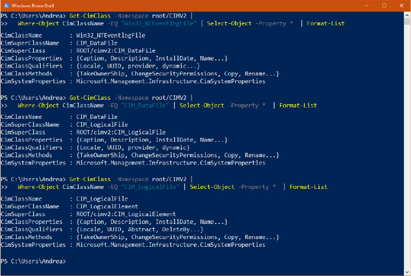
Figure 10-28 Windows PowerShell extracting information from the Win32_NTEventlogFile class.
As stated earlier, WMI provider developers write their classes in the MOF language. The following output shows the definition of the Event Log provider’s Win32_NTEventlogFile, which has been queried in Figure 10-28:
[dynamic: ToInstance, provider("MS_NT_EVENTLOG_PROVIDER"): ToInstance, SupportsUpdate,
Locale(1033): ToInstance, UUID("{8502C57B-5FBB-11D2-AAC1-006008C78BC7}"): ToInstance]
class Win32_NTEventlogFile : CIM_DataFile
{
   [Fixed: ToSubClass, read: ToSubClass] string LogfileName;
   [read: ToSubClass, write: ToSubClass] uint32 MaxFileSize;
   [read: ToSubClass] uint32 NumberOfRecords;
   [read: ToSubClass, volatile: ToSubClass, ValueMap{"0", "1..365", "4294967295"}:
    ToSubClass] string OverWritePolicy;
   [read: ToSubClass, write: ToSubClass, Range("0-365 | 4294967295"): ToSubClass]
    uint32 OverwriteOutDated;
   [read: ToSubClass] string Sources[];
   [ValueMap{"0", "8", "21", ".."}: ToSubClass, implemented, Privileges{
    "SeSecurityPrivilege", "SeBackupPrivilege"}: ToSubClass]
      uint32 ClearEventlog([in] string ArchiveFileName);
   [ValueMap{"0", "8", "21", "183", ".."}: ToSubClass, implemented, Privileges{
    "SeSecurityPrivilege", "SeBackupPrivilege"}: ToSubClass]
      uint32 BackupEventlog([in] string ArchiveFileName);
};
One term worth reviewing is dynamic, which is a descriptive designator for the Win32_NTEventlogFile class that the MOF file in the preceding output shows. Dynamic means that the WMI infrastructure asks the WMI provider for the values of properties associated with an object of that class whenever a management application queries the object’s properties. A static class is one in the WMI repository; the WMI infrastructure refers to the repository to obtain the values instead of asking a provider for the values. Because updating the repository is a relatively expensive operation, dynamic providers are more efficient for objects that have properties that change frequently.
Type Wbemtest in the Cortana search box and press Enter. The Windows Management Instrumentation Tester should open.
Click the Connect button, change the Namespace to rootcimv2, and connect. The tool should enable all the command buttons, as shown in the following figure:
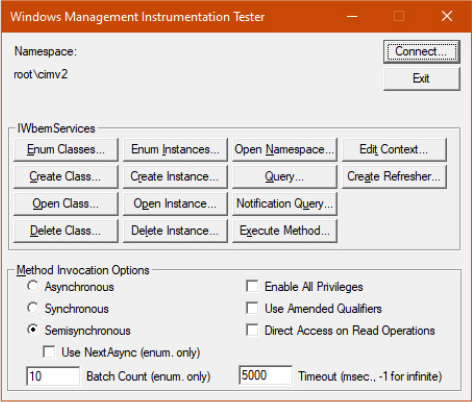
Click the Enum Classes button, select the Recursive option button, and then click OK.
Find Win32_NTEventLogFile in the list of classes, and then double-click it to see its class properties.
Click the Show MOF button to open a window that displays the MOF text.
After constructing classes in MOF, WMI developers can supply the class definitions to WMI in several ways. WDM driver developers compile a MOF file into a binary MOF (BMF) file—a more compact binary representation than an MOF file—and can choose to dynamically give the BMF files to the WDM infrastructure or to statically include it in their binary. Another way is for the provider to compile the MOF and use WMI COM APIs to give the definitions to the WMI infrastructure. Finally, a provider can use the MOF Compiler (Mofcomp.exe) tool to give the WMI infrastructure a classes-compiled representation directly.
![]() Note
Note
Previous editions of Windows (until Windows 7) provided a graphical tool, called WMI CIM Studio, shipped with the WMI Administrative Tool. The tool was able to graphically show WMI namespaces, classes, properties, and methods. Nowadays, the tool is not supported or available for download because it was superseded by the WMI capacities of Windows PowerShell. PowerShell is a scripting language that does not run with a GUI. Some third-party tools present a similar interface of CIM Studio. One of them is WMI Explorer, which is downloadable from https://github.com/vinaypamnani/wmie2/releases.
The Common Information Model (CIM) repository is stored in the %SystemRoot%System32wbemRepository path and includes the following:
■ Index.btr Binary-tree (btree) index file
■ MappingX.map Transaction control files (X is a number starting from 1)
■ Objects.data CIM repository where managed resource definitions are stored
The WMI namespace
Classes define objects, which are provided by a WMI provider. Objects are class instances on a system. WMI uses a namespace that contains several subnamespaces that WMI arranges hierarchically to organize objects. A management application must connect to a namespace before the application can access objects within the namespace.
WMI names the namespace root directory ROOT. All WMI installations have four predefined namespaces that reside beneath root: CIMV2, Default, Security, and WMI. Some of these namespaces have other namespaces within them. For example, CIMV2 includes the Applications and ms_409 namespaces as subnamespaces. Providers sometimes define their own namespaces; you can see the WMI namespace (which the Windows device driver WMI provider defines) beneath ROOT in Windows.
Unlike a file system namespace, which comprises a hierarchy of directories and files, a WMI namespace is only one level deep. Instead of using names as a file system does, WMI uses object properties that it defines as keys to identify the objects. Management applications specify class names with key names to locate specific objects within a namespace. Thus, each instance of a class must be uniquely identifiable by its key values. For example, the Event Log provider uses the Win32_NTLogEvent class to represent records in an Event Log. This class has two keys: Logfile, a string; and RecordNumber, an unsigned integer. A management application that queries WMI for instances of Event Log records obtains them from the provider key pairs that identify records. The application refers to a record using the syntax that you see in this sample object path name:
\ANDREA-LAPTOP
ootCIMV2:Win32_NTLogEvent.Logfile="Application",
                                                     RecordNumber="1"
The first component in the name (\ANDREA-LAPTOP) identifies the computer on which the object is located, and the second component ( ootCIMV2) is the namespace in which the object resides. The class name follows the colon, and key names and their associated values follow the period. A comma separates the key values.
WMI provides interfaces that let applications enumerate all the objects in a particular class or to make queries that return instances of a class that match a query criterion.
Class association
Many object types are related to one another in some way. For example, a computer object has a processor, software, an operating system, active processes, and so on. WMI lets providers construct an association class to represent a logical connection between two different classes. Association classes associate one class with another, so the classes have only two properties: a class name and the Ref modifier. The following output shows an association in which the Event Log provider’s MOF file associates the Win32_NTLogEvent class with the Win32_ComputerSystem class. Given an object, a management application can query associated objects. In this way, a provider defines a hierarchy of objects.
[dynamic: ToInstance, provider("MS_NT_EVENTLOG_PROVIDER"): ToInstance, EnumPrivileges{"SeSe
curityPrivilege"}: ToSubClass, Privileges{"SeSecurityPrivilege"}: ToSubClass, Locale(1033):
ToInstance, UUID("{8502C57F-5FBB-11D2-AAC1-006008C78BC7}"): ToInstance, Association:
DisableOverride ToInstance ToSubClass]
class Win32_NTLogEventComputer
{
   [key, read: ToSubClass] Win32_ComputerSystem ref Computer;
   [key, read: ToSubClass] Win32_NTLogEvent ref Record;
};
Figure 10-29 shows a PowerShell window displaying the first Win32_NTLogEventComputer class instance located in the CIMV2 namespace. From the aggregated class instance, a user can query the associated Win32_ComputerSystem object instance WIN-46E4EFTBP6Q, which generated the event with record number 1031 in the Application log file.
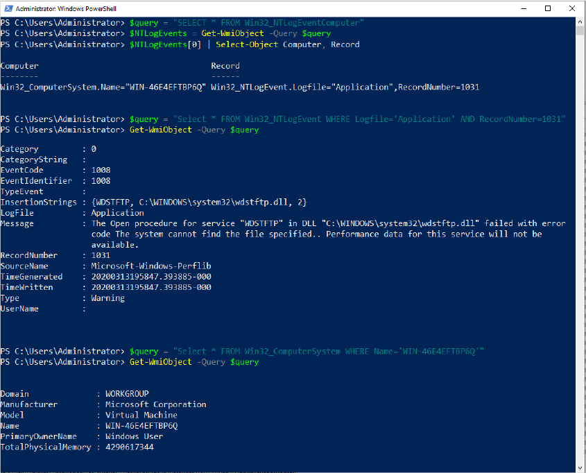
Figure 10-29 The Win32_NTLogEventComputer association class.
WMI implementation
The WMI service runs in a shared Svchost process that executes in the local system account. It loads providers into the WmiPrvSE.exe provider-hosting process, which launches as a child of the DCOM Launcher (RPC service) process. WMI executes Wmiprvse in the local system, local service, or network service account, depending on the value of the HostingModel property of the WMI Win32Provider object instance that represents the provider implementation. A Wmiprvse process exits after the provider is removed from the cache, one minute following the last provider request it receives.
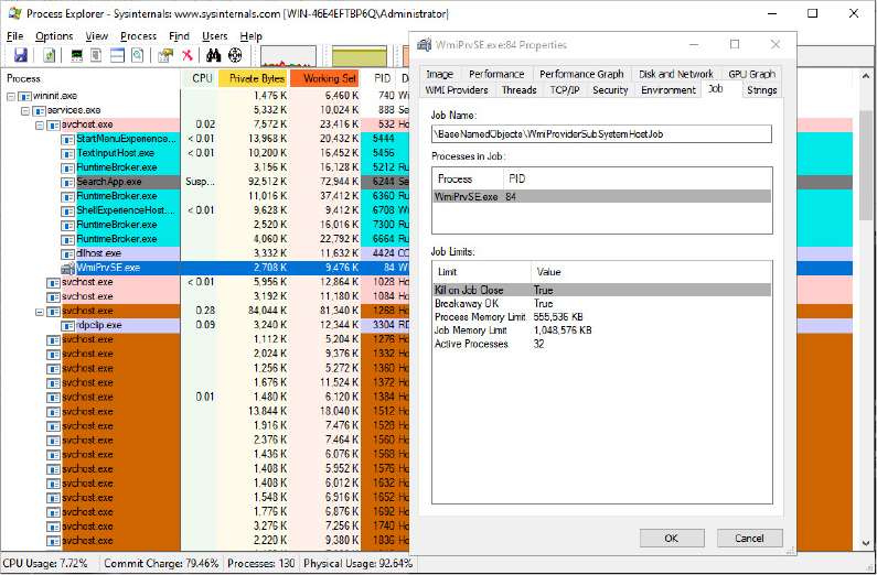
Most WMI components reside by default in %SystemRoot%System32 and %SystemRoot%System32Wbem, including Windows MOF files, built-in provider DLLs, and management application WMI DLLs. Look in the %SystemRoot%System32Wbem directory, and you’ll find Ntevt.mof, the Event Log provider MOF file. You’ll also find Ntevt.dll, the Event Log provider’s DLL, which the WMI service uses.
Providers are generally implemented as dynamic link libraries (DLLs) exposing COM servers that implement a specified set of interfaces (IWbemServices is the central one. Generally, a single provider is implemented as a single COM server). WMI includes many built-in providers for the Windows family of operating systems. The built-in providers, also known as standard providers, supply data and management functions from well-known operating system sources such as the Win32 subsystem, event logs, performance counters, and registry. Table 10-15 lists several of the standard WMI providers included with Windows.
Table 10-15 Standard WMI providers included with Windows
Provider |
Binary |
Namespace |
Description |
|---|---|---|---|
Active Directory provider |
dsprov.dll |
rootdirectoryldap |
Maps Active Directory objects to WMI |
Event Log provider |
ntevt.dll |
rootcimv2 |
Manages Windows event logs—for example, read, backup, clear, copy, delete, monitor, rename, compress, uncompress, and change event log settings |
Performance Counter provider |
wbemperf.dll |
rootcimv2 |
Provides access to raw performance data |
Registry provider |
stdprov.dll |
rootdefault |
Reads, writes, enumerates, monitors, creates, and deletes registry keys and values |
Virtualization provider |
vmmsprox.dll |
rootvirtualizationv2 |
Provides access to virtualization services implemented in vmms.exe, like managing virtual machines in the host system and retrieving information of the host system peripherals from a guest VM |
WDM provider |
wmiprov.dll |
rootwmi |
Provides access to information on WDM device drivers |
Win32 provider |
cimwin32.dll |
rootcimv2 |
Provides information about the computer, disks, peripheral devices, files, folders, file systems, networking components, operating system, printers, processes, security, services, shares, SAM users and groups, and more |
Windows Installer provider |
msiprov.dll |
rootcimv2 |
Provides access to information about installed software |
Ntevt.dll, the Event Log provider DLL, is a COM server, registered in the HKLMSoftwareClassesCLSID registry key with the {F55C5B4C-517D-11d1-AB57-00C04FD9159E} CLSID. (You can find it in the MOF descriptor.) Directories beneath %SystemRoot%System32Wbem store the repository, log files, and third-party MOF files. WMI implements the repository—named the CIMOM object repository—using a proprietary version of the Microsoft JET database engine. The database file, by default, resides in SystemRoot%System32WbemRepository.
WMI honors numerous registry settings that the service’s HKLMSOFTWAREMicrosoftWBEMCIMOM registry key stores, such as thresholds and maximum values for certain parameters.
Device drivers use special interfaces to provide data to and accept commands—called the WMI System Control commands—from WMI. These interfaces are part of the WDM, which is explained in Chapter 6 of Part 1. Because the interfaces are cross-platform, they fall under the ootWMI namespace.
WMI security
WMI implements security at the namespace level. If a management application successfully connects to a namespace, the application can view and access the properties of all the objects in that namespace. An administrator can use the WMI Control application to control which users can access a namespace. Internally, this security model is implemented by using ACLs and Security Descriptors, part of the standard Windows security model that implements Access Checks. (See Chapter 7 of Part 1 for more information on access checks.)
To start the WMI Control application, open the Control Panel by typing Computer Management in the Cortana search box. Next, open the Services And Applications node. Right-click WMI Control and select Properties to launch the WMI Control Properties dialog box, as shown in Figure 10-30. To configure security for namespaces, click the Security tab, select the namespace, and click Security. The other tabs in the WMI Control Properties dialog box let you modify the performance and backup settings that the registry stores.

Figure 10-30 The WMI Control Properties application and the Security tab of the rootvirtualizationv2 namespace.
Event Tracing for Windows (ETW)
Event Tracing for Windows (ETW) is the main facility that provides to applications and kernel-mode drivers the ability to provide, consume, and manage log and trace events. The events can be stored in a log file or in a circular buffer, or they can be consumed in real time. They can be used for debugging a driver, a framework like the .NET CLR, or an application and to understand whether there could be potential performance issues. The ETW facility is mainly implemented in the NT kernel, but an application can also use private loggers, which do not transition to kernel-mode at all. An application that uses ETW can be one of the following categories:
■ Controller A controller starts and stops event tracing sessions, manages the size of the buffer pools, and enables providers so they can log events to the session. Example controllers include Reliability and Performance Monitor and XPerf from the Windows Performance Toolkit (now part of the Windows Assessment and Deployment Kit, available for download from https://docs.microsoft.com/en-us/windows-hardware/get-started/adk-install).
■ Provider A provider is an application or a driver that contains event tracing instrumentation. A provider registers with ETW a provider GUID (globally unique identifiers), which defines the events it can produce. After the registration, the provider can generate events, which can be enabled or disabled by the controller application through an associated trace session.
■ Consumer A consumer is an application that selects one or more trace sessions for which it wants to read trace data. Consumers can receive events stored in log files, in a circular buffer, or from sessions that deliver events in real time.
It’s important to mention that in ETW, every provider, session, trait, and provider’s group is represented by a GUID (more information about these concepts are provided later in this chapter). Four different technologies used for providing events are built on the top of ETW. They differ mainly in the method in which they store and define events (there are other distinctions though):
■ MOF (or classic) providers are the legacy ones, used especially by WMI. MOF providers store the events descriptor in MOF classes so that the consumer knows how to consume them.
■ WPP (Windows software trace processor) providers are used for tracing the operations of an application or driver (they are an extension of WMI event tracing) and use a TMF (trace message format) file for allowing the consumer to decode trace events.
■ Manifest-based providers use an XML manifest file to define events that can be decoded by the consumer.
■ TraceLogging providers, which, like WPP providers are used for fast tracing the operation of an application of driver, use self-describing events that contain all the required information for the consumption by the controller.
When first installed, Windows already includes dozens of providers, which are used by each component of the OS for logging diagnostics events and performance traces. For example, Hyper-V has multiple providers, which provide tracing events for the Hypervisor, Dynamic Memory, Vid driver, and Virtualization stack. As shown in Figure 10-31, ETW is implemented in different components:
■ Most of the ETW implementation (global session creation, provider registration and enablement, main logger thread) resides in the NT kernel.
■ The Host for SCM/SDDL/LSA Lookup APIs library (sechost.dll) provides to applications the main user-mode APIs used for creating an ETW session, enabling providers and consuming events. Sechost uses services provided by Ntdll to invoke ETW in the NT kernel. Some ETW user-mode APIs are implemented directly in Ntdll without exposing the functionality to Sechost. Provider registration and events generation are examples of user-mode functionalities that are implemented in Ntdll (and not in Sechost).
■ The Event Trace Decode Helper Library (TDH.dll) implements services available for consumers to decode ETW events.
■ The Eventing Consumption and Configuration library (WevtApi.dll) implements the Windows Event Log APIs (also known as Evt APIs), which are available to consumer applications for managing providers and events on local and remote machines. Windows Event Log APIs support XPath 1.0 or structured XML queries for parsing events produced by an ETW session.
■ The Secure Kernel implements basic secure services able to interact with ETW in the NT kernel that lives in VTL 0. This allows trustlets and the Secure Kernel to use ETW for logging their own secure events.
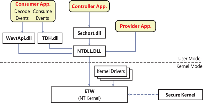
Figure 10-31 ETW architecture.
ETW initialization
The ETW initialization starts early in the NT kernel startup (for more details on the NT kernel initialization, see Chapter 12). It is orchestrated by the internal EtwInitialize function in three phases. The phase 0 of the NT kernel initialization calls EtwInitialize to properly allocate and initialize the per-silo ETW-specific data structure that stores the array of logger contexts representing global ETW sessions (see the “ETW session” section later in this chapter for more details). The maximum number of global sessions is queried from the HKLMSystemCurrentControlSetControlWMIEtwMaxLoggers registry value, which should be between 32 and 256, (64 is the default number in case the registry value does not exist).
Later, in the NT kernel startup, the IoInitSystemPreDrivers routine of phase 1 continues with the initialization of ETW, which performs the following steps:
Acquires the system startup time and reference system time and calculates the QPC frequency.
Initializes the ETW security key and reads the default session and provider’s security descriptor.
Initializes the per-processor global tracing structures located in the PRCB.
Creates the real-time ETW consumer object type (called EtwConsumer), which is used to allow a user-mode real-time consumer process to connect to the main ETW logger thread and the ETW registration (internally called EtwRegistration) object type, which allow a provider to be registered from a user-mode application.
Registers the ETW bugcheck callback, used to dump logger sessions data in the bugcheck dump.
Initializes and starts the Global logger and Autologgers sessions, based on the AutoLogger and GlobalLogger registry keys located under the HKLMSystemCurrentControlSetControlWMI root key.
Uses the EtwRegister kernel API to register various NT kernel event providers, like the Kernel Event Tracing, General Events provider, Process, Network, Disk, File Name, IO, and Memory providers, and so on.
Publishes the ETW initialized WNF state name to indicate that the ETW subsystem is initialized.
Writes the SystemStart event to both the Global Trace logging and General Events providers. The event, which is shown in Figure 10-32, logs the approximate OS Startup time.
If required, loads the FileInfo driver, which provides supplemental information on files I/O to Superfetch (more information on the Proactive memory management is available in Chapter 5 of Part 1).

Figure 10-32 The SystemStart ETW event displayed by the Event Viewer.
In early boot phases, the Windows registry and I/O subsystems are still not completely initialized. So ETW can’t directly write to the log files. Late in the boot process, after the Session Manager (SMSS.exe) has correctly initialized the software hive, the last phase of ETW initialization takes place. The purpose of this phase is just to inform each already-registered global ETW session that the file system is ready, so that they can flush out all the events that are recorded in the ETW buffers to the log file.
ETW sessions
One of the most important entities of ETW is the Session (internally called logger instance), which is a glue between providers and consumers. An event tracing session records events from one or more providers that a controller has enabled. A session usually contains all the information that describes which events should be recorded by which providers and how the events should be processed. For example, a session might be configured to accept all events from the Microsoft-Windows-Hyper-V-Hypervisor provider (which is internally identified using the {52fc89f8-995e-434c-a91e-199986449890} GUID). The user can also configure filters. Each event generated by a provider (or a provider group) can be filtered based on event level (information, warning, error, or critical), event keyword, event ID, and other characteristics. The session configuration can also define various other details for the session, such as what time source should be used for the event timestamps (for example, QPC, TSC, or system time), which events should have stack traces captured, and so on. The session has the important rule to host the ETW logger thread, which is the main entity that flushes the events to the log file or delivers them to the real-time consumer.
Sessions are created using the StartTrace API and configured using ControlTrace and EnableTraceEx2. Command-line tools such as xperf, logman, tracelog, and wevtutil use these APIs to start or control trace sessions. A session also can be configured to be private to the process that creates it. In this case, ETW is used for consuming events created only by the same application that also acts as provider. The application thus eliminates the overhead associated with the kernel-mode transition. Private ETW sessions can record only events for the threads of the process in which it is executing and cannot be used with real-time delivery. The internal architecture of private ETW is not described in this book.
When a global session is created, the StartTrace API validates the parameters and copies them in a data structure, which the NtTraceControl API uses to invoke the internal function EtwpStartLogger in the kernel. An ETW session is represented internally through an ETW_LOGGER_CONTEXT data structure, which contains the important pointers to the session memory buffers, where the events are written to. As discussed in the “ETW initialization” section, a system can support a limited number of ETW sessions, which are stored in an array located in a global per-SILO data structure. EtwpStartLogger checks the global sessions array, determining whether there is free space or if a session with the same name already exists. If that is the case, it exits and signals an error. Otherwise, it generates a session GUID (if not already specified by the caller), allocates and initializes an ETW_LOGGER_CONTEXT data structure representing the session, assigns to it an index, and inserts it in the per-silo array.
ETW queries the session’s security descriptor located in the HKLMSystemCurrentControlSetControlWmiSecurity registry key. As shown in Figure 10-33, each registry value in the key is named as the session GUID (the registry key, however, also contains the provider’s GUID) and contains the binary representation of a self-relative security descriptor. If a security descriptor for the session does not exist, a default one is returned for the session (see the “Witnessing the default security descriptor of ETW sessions” experiment later in this chapter for details).
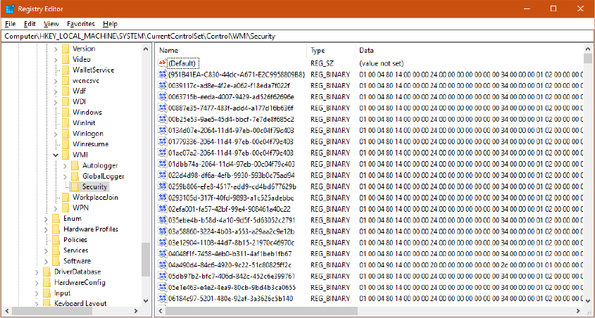
Figure 10-33 The ETW security registry key.
The EtwpStartLogger function performs an access check on the session’s security descriptor, requesting the TRACELOG_GUID_ENABLE access right (and the TRACELOG_CREATE_REALTIME or TRACELOG_CREATE_ONDISK depending on the log file mode) using the current process’s access token. If the check succeeds, the routine calculates the default size and numbers of event buffers, which are calculated based on the size of the system physical memory (the default buffer size is 8, 16, or 64KB). The number of buffers depends on the number of system processors and on the presence of the EVENT_TRACE_NO_PER_PROCESSOR_BUFFERING logger mode flag, which prevents events (which can be generated from different processors) to be written to a per-processor buffer.
ETW acquires the session’s initial reference time stamp. Three clock resolutions are currently supported: Query performance counter (QPC, a high-resolution time stamp not affected by the system clock), System time, and CPU cycle counter. The EtwpAllocateTraceBuffer function is used to allocate each buffer associated with the logger session (the number of buffers was calculated before or specified as input from the user). A buffer can be allocated from the paged pool, nonpaged pool, or directly from physical large pages, depending on the logging mode. Each buffer is stored in multiple internal per-session lists, which are able to provide fast lookup both to the ETW main logger thread and ETW providers. Finally, if the log mode is not set to a circular buffer, the EtwpStartLogger function starts the main ETW logger thread, which has the goal of flushing events written by the providers associated with the session to the log file or to the real-time consumer. After the main thread is started, ETW sends a session notification to the registered session notification provider (GUID 2a6e185b-90de-4fc5-826c-9f44e608a427), a special provider that allows its consumers to be informed when certain ETW events happen (like a new session being created or destroyed, a new log file being created, or a log error being raised).
xperf -Loggers
xperf -Loggers > ETW_Sessions.txt
Logger Name           : EventLog-Application
Logger Id             : 9
Logger Thread Id      : 000000000000008C
Buffer Size           : 64
Maximum Buffers       : 64
Minimum Buffers       : 2
Number of Buffers     : 2
Free Buffers          : 2
Buffers Written       : 252
Events Lost           : 0
Log Buffers Lost      : 0
Real Time Buffers Lost: 0
Flush Timer           : 1
Age Limit             : 0
Real Time Mode        : Enabled
Log File Mode         : Secure PersistOnHybridShutdown PagedMemory IndependentSession
NoPerProcessorBuffering
Maximum File Size     : 100
Log Filename          :
Trace Flags           : "Microsoft-Windows-CertificateServicesClient-Lifecycle-User":0x800
0000000000000:0xff+"Microsoft-Windows-SenseIR":0x8000000000000000:0xff+
... (output cut for space reasons)
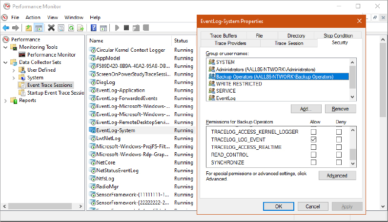
ETW providers
As stated in the previous sections, a provider is a component that produces events (while the application that includes the provider contains event tracing instrumentation). ETW supports different kinds of providers, which all share a similar programming model. (They are mainly different in the way in which they encode events.) A provider must be initially registered with ETW before it can generate any event. In a similar way, a controller application should enable the provider and associate it with an ETW session to be able to receive events from the provider. If no session has enabled a provider, the provider will not generate any event. The provider defines its interpretation of being enabled or disabled. Generally, an enabled provider generates events, and a disabled provider does not.
Providers registration
Each provider’s type has its own API that needs to be called by a provider application (or driver) for registering a provider. For example, manifest-based providers rely on the EventRegister API for user-mode registrations, and EtwRegister for kernel-mode registrations. All the provider types end up calling the internal EtwpRegisterProvider function, which performs the actual registration process (and is implemented in both the NT kernel and NTDLL). The latter allocates and initializes an ETW_GUID_ENTRY data structure, which represents the provider (the same data structure is used for notifications and traits). The data structure contains important information, like the provider GUID, security descriptor, reference counter, enablement information (for each ETW session that enables the provider), and a list of provider’s registrations.
For user-mode provider registrations, the NT kernel performs an access check on the calling process’s token, requesting the TRACELOG_REGISTER_GUIDS access right. If the check succeeds, or if the registration request originated from kernel code, ETW inserts the new ETW_GUID_ENTRY data structure in a hash table located in the global ETW per-silo data structure, using a hash of the provider’s GUID as the table’s key (this allows fast lookup of all the providers registered in the system.) In case an entry with the same GUID already exists in the hash table, ETW uses the existing entry instead of the new one. A GUID could already exist in the hash table mainly for two reasons:
■ Another driver or application has enabled the provider before it has been actually registered (see the “Providers enablement” section later in this chapter for more details) .
■ The provider has been already registered once. Multiple registration of the same provider GUID are supported.
After the provider has been successfully added into the global list, ETW creates and initializes an ETW registration object, which represents a single registration. The object encapsulates an ETW_REG_ENTRY data structure, which ties the provider to the process and session that requested its registration. (ETW also supports registration from different sessions.) The object is inserted in a list located in the ETW_GUID_ENTRY (the EtwRegistration object type has been previously created and registered with the NT object manager at ETW initialization time). Figure 10-34 shows the two data structures and their relationships. In the figure, two providers’ processes (process A, living in session 4, and process B, living in session 16) have registered for provider 1. Thus two ETW_REG_ENTRY data structures have been created and linked to the ETW_GUID_ENTRY representing provider 1.
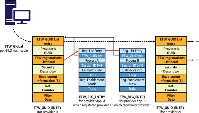
Figure 10-34 The ETW_GUID_ENTRY data structure and the ETW_REG_ENTRY.
At this stage, the provider is registered and ready to be enabled in the session(s) that requested it (through the EnableTrace API). In case the provider has been already enabled in at least one session before its registration, ETW enables it (see the next section for details) and calls the Enablement callback, which can be specified by the caller of the EventRegister (or EtwRegister) API that started the registration process.
Provider Enablement
As introduced in the previous section, a provider should be associated with an ETW session to be able to generate events. This association is called Provider Enablement, and it can happen in two ways: before or after the provider is registered. A controller application can enable a provider on a session through the EnableTraceEx API. The API allows you to specify a bitmask of keywords that determine the category of events that the session wants to receive. In the same way, the API supports advanced filters on other kinds of data, like the process IDs that generate the events, package ID, executable name, and so on. (You can find more information at https://docs.microsoft.com/en-us/windows/win32/api/evntprov/ns-evntprov-event_filter_descriptor.)
Provider Enablement is managed by ETW in kernel mode through the internal EtwpEnableGuid function. For user-mode requests, the function performs an access check on both the session and provider security descriptors, requesting the TRACELOG_GUID_ENABLE access right on behalf of the calling process’s token. If the logger session includes the SECURITY_TRACE flag, EtwpEnableGuid requires that the calling process is a PPL (see the “ETW security” section later in this chapter for more details). If the check succeeds, the function performs a similar task to the one discussed previously for provider registrations:
■ It allocates and initializes an ETW_GUID_ENTRY data structure to represent the provider or use the one already linked in the global ETW per-silo data structure in case the provider has been already registered.
■ Links the provider to the logger session by adding the relative session enablement information in the ETW_GUID_ENTRY.
In case the provider has not been previously registered, no ETW registration object exists that’s linked in the ETW_GUID_ENTRY data structure, so the procedure terminates. (The provider will be enabled after it is first registered.) Otherwise, the provider is enabled.
While legacy MOF providers and WPP providers can be enabled only to one session at time, Manifest-based and Tracelogging providers can be enabled on a maximum of eight sessions. As previously shown in Figure 10-32, the ETW_GUID_ENTRY data structure contains enablement information for each possible ETW session that enabled the provider (eight maximum). Based on the enabled sessions, the EtwpEnableGuid function calculates a new session enablement mask, storing it in the ETW_REG_ENTRY data structure (representing the provider registration). The mask is very important because it’s the key for event generations. When an application or driver writes an event to the provider, a check is made: if a bit in the enablement mask equals 1, it means that the event should be written to the buffer maintained by a particular ETW session; otherwise, the session is skipped and the event is not written to its buffer.
Note that for secure sessions, a supplemental access check is performed before updating the session enablement mask in the provider registration. The ETW session’s security descriptor should allow the TRACELOG_LOG_EVENT access right to the calling process’s access token. Otherwise, the relative bit in the enablement mask is not set to 1. (The target ETW session will not receive any event from the provider registration.) More information on secure sessions is available in the “Secure loggers and ETW security” section later in this chapter.
Providing events
After registering one or more ETW providers, a provider application can start to generate events. Note that events can be generated even though a controller application hasn’t had the chance to enable the provider in an ETW session. The way in which an application or driver can generate events depends on the type of the provider. For example, applications that write events to manifest-based providers usually directly create an event descriptor (which respects the XML manifest) and use the EventWrite API to write the event to the ETW sessions that have the provider enabled. Applications that manage MOF and WPP providers rely on the TraceEvent API instead.
Events generated by manifest-based providers, as discussed previously in the “ETW session” section, can be filtered by multiple means. ETW locates the ETW_GUID_ENTRY data structure from the provider registration object, which is provided by the application through a handle. The internal EtwpEventWriteFull function uses the provider’s registration session enablement mask to cycle between all the enabled ETW sessions associated with the provider (represented by an ETW_LOGGER_CONTEXT). For each session, it checks whether the event satisfies all the filters. If so, it calculates the full size of the event’s payload and checks whether there is enough free space in the session’s current buffer.
If there is no available space, ETW checks whether there is another free buffer in the session: free buffers are stored in a FIFO (first-in, first-out) queue. If there is a free buffer, ETW marks the old buffer as “dirty” and switches to the new free one. In this way, the Logger thread can wake up and flush the entire buffer to a log file or deliver it to a real-time consumer. If the session’s log mode is a circular logger, no logger thread is ever created: ETW simply links the old full buffer at the end of the free buffers queue (as a result the queue will never be empty). Otherwise, if there isn’t a free buffer in the queue, ETW tries to allocate an additional buffer before returning an error to the caller.
After enough space in a buffer is found, EtwpEventWriteFull atomically writes the entire event payload in the buffer and exits. Note that in case the session enablement mask is 0, it means that no sessions are associated with the provider. As a result, the event is lost and not logged anywhere.
MOF and WPP events go through a similar procedure but support only a single ETW session and generally support fewer filters. For these kinds of providers, a supplemental check is performed on the associated session: If the controller application has marked the session as secure, nobody can write any events. In this case, an error is yielded back to the caller (secure sessions are discussed later in the “Secure loggers and ETW security” section).
ETW Logger thread
The Logger thread is one of the most important entities in ETW. Its main purpose is to flush events to the log file or deliver them to the real-time consumer, keeping track of the number of delivered and lost events. A logger thread is started every time an ETW session is initially created, but only in case the session does not use the circular log mode. Its execution logic is simple. After it’s started, it links itself to the ETW_LOGGER_CONTEXT data structure representing the associated ETW session and waits on two main synchronization objects. The Flush event is signaled by ETW every time a buffer belonging to a session becomes full (which can happen after a new event has been generated by a provider—for example, as discussed in the previous section, “Providing events”), when a new real-time consumer has requested to be connected, or when a logger session is going to be stopped. The TimeOut timer is initialized to a valid value (usually 1 second) only in case the session is a real-time one or in case the user has explicitly required it when calling the StartTrace API for creating the new session.
When one of the two synchronization objects is signaled, the logger thread rearms them and checks whether the file system is ready. If not, the main logger thread returns to sleep again (no sessions should be flushed in early boot stages). Otherwise, it starts to flush each buffer belonging to the session to the log file or the real-time consumer.
For real-time sessions, the logger thread first creates a temporary per-session ETL file in the %SystemRoot% System32LogFilesWMIRtBackup folder (as shown in Figure 10-35.) The log file name is generated by adding the EtwRT prefix to the name of the real-time session. The file is used for saving temporary events before they are delivered to a real-time consumer (the log file can also store lost events that have not been delivered to the consumer in the proper time frame). When started, real-time auto-loggers restore lost events from the log file with the goal of delivering them to their consumer.
Figure 10-35 Real-time temporary ETL log files.
The logger thread is the only entity able to establish a connection between a real-time consumer and the session. The first time that a consumer calls the ProcessTrace API for receiving events from a real-time session, ETW sets up a new RealTimeConsumer object and uses it with the goal of creating a link between the consumer and the real-time session. The object, which resolves to an ETW_REALTIME_CONSUMER data structure in the NT kernel, allows events to be “injected” in the consumer’s process address space (another user-mode buffer is provided by the consumer application).
For non–real-time sessions, the logger thread opens (or creates, in case the file does not exist) the initial ETL log file specified by the entity that created the session. The logger thread can also create a brand-new log file in case the session’s log mode specifies the EVENT_TRACE_FILE_MODE_NEWFILE flag, and the current log file reaches the maximum size.
At this stage, the ETW logger thread initiates a flush of all the buffers associated with the session to the current log file (which, as discussed, can be a temporary one for real-time sessions). The flush is performed by adding an event header to each event in the buffer and by using the NtWriteFile API for writing the binary content to the ETL log file. For real-time sessions, the next time the logger thread wakes up, it is able to inject all the events stored in the temporary log file to the target user-mode real-time consumer application. Thus, for real-time sessions, ETW events are never delivered synchronously.
Consuming events
Events consumption in ETW is performed almost entirely in user mode by a consumer application, thanks to the services provided by the Sechost.dll. The consumer application uses the OpenTrace API for opening an ETL log file produced by the main logger thread or for establishing the connection to a real-time logger. The application specifies an event callback function, which is called every time ETW consumes a single event. Furthermore, for real-time sessions, the application can supply an optional buffer-callback function, which receives statistics for each buffer that ETW flushes and is called every time a single buffer is full and has been delivered to the consumer.
The actual event consumption is started by the ProcessTrace API. The API works for both standard and real-time sessions, depending on the log file mode flags passed previously to OpenTrace.
For real-time sessions, the API uses kernel mode services (accessed through the NtTraceControl system call) to verify that the ETW session is really a real-time one. The NT kernel verifies that the security descriptor of the ETW session grants the TRACELOG_ACCESS_REALTIME access right to the caller process’s token. If it doesn’t have access, the API fails and returns an error to the controller application. Otherwise, it allocates a temporary user-mode buffer and a bitmap used for receiving events and connects to the main logger thread (which creates the associated EtwConsumer object; see the “ETW logger thread” section earlier in this chapter for details). Once the connection is established, the API waits for new data arriving from the session’s logger thread. When the data comes, the API enumerates each event and calls the event callback.
For normal non–real-time ETW sessions, the ProcessTrace API performs a similar processing, but instead of connecting to the logger thread, it just opens and parses the ETL log file, reading each buffer one by one and calling the event callback for each found event (events are sorted in chronological order). Differently from real-time loggers, which can be consumed one per time, in this case the API can work even with multiple trace handles created by the OpenTrace API, which means that it can parse events from different ETL log files.
Events belonging to ETW sessions that use circular buffers are not processed using the described methodology. (There is indeed no logger thread that dumps any event.) Usually a controller application uses the FlushTrace API when it wants to dump a snapshot of the current buffers belonging to an ETW session configured to use a circular buffer into a log file. The API invokes the NT kernel through the NtTraceControl system call, which locates the ETW session and verifies that its security descriptor grants the TRACELOG_CREATE_ONDISK access right to the calling process’s access token. If so, and if the controller application has specified a valid log file name, the NT kernel invokes the internal EtwpBufferingModeFlush routine, which creates the new ETL file, adds the proper headers, and writes all the buffers associated with the session. A consumer application can then parse the events written in the new log file by using the OpenTrace and ProcessTrace APIs, as described earlier.
Events decoding
When the ProcessTrace API identifies a new event in an ETW buffer, it calls the event callback, which is generally located in the consumer application. To be able to correctly process the event, the consumer application should decode the event payload. The Event Trace Decode Helper Library (TDH.dll) provides services to consumer applications for decoding events. As discussed in the previous sections, a provider application (or driver), should include information that describes how to decode the events generated by its registered providers.
This information is encoded differently based on the provider type. Manifest-based providers, for example, compile the XML descriptor of their events in a binary file and store it in the resource section of their provider application (or driver). As part of provider registration, a setup application should register the provider’s binary in the HKLMSOFTWAREMicrosoftWindowsCurrentVersionWINEVTPublishers registry key. The latter is important for event decoding, especially for the following reasons:
■ The system consults the Publishers key when it wants to resolve a provider name to its GUID (from an ETW point of view, providers do not have a name). This allows tools like Xperf to display readable provider names instead of their GUIDs.
■ The Trace Decode Helper Library consults the key to retrieve the provider’s binary file, parse its resource section, and read the binary content of the events descriptor.
After the event descriptor is obtained, the Trace Decode Helper Library gains all the needed information for decoding the event (by parsing the binary descriptor) and allows consumer applications to use the TdhGetEventInformation API to retrieve all the fields that compose the event’s payload and the correct interpretation the data associated with them. TDH follows a similar procedure for MOF and WPP providers (while TraceLogging incorporates all the decoding data in the event payload, which follows a standard binary format).
Note that all events are natively stored by ETW in an ETL log file, which has a well-defined uncompressed binary format and does not contain event decoding information. This means that if an ETL file is opened by another system that has not acquired the trace, there is a good probability that it will not be able to decode the events. To overcome these issues, the Event Viewer uses another binary format: EVTX. This format includes all the events and their decoding information and can be easily parsed by any application. An application can use the EvtExportLog Windows Event Log API to save the events included in an ETL file with their decoding information in an EVTX file.
Open a command prompt and move to the folder where the ETL file produced by the previous experiment (“Listing processes activity using ETW”) resides and insert
netsh trace convert input=process_trace.etl output=process_trace.txt dump=txt
overwrite=yes
where
process_trace.etlis the name of the input log file, andprocess_trace.txtfile is the name of the output decoded text file.If you open the text file, you will find all the decoded events (one for each line) with a description, like the following:
[2]1B0C.1154::2020-05-01 12:00:42.075601200 [Microsoft-Windows-Kernel-Process]
Process 1808 started at time 2020 - 05 - 01T19:00:42.075562700Z by parent 6924
running in session 1 with name DeviceHarddiskVolume4WindowsSystem32
otepad.
exe.
From the log, you will find that rarely some events are not decoded completely or do not contain any description. This is because the provider manifest does not include the needed information (a good example is given from the ThreadWorkOnBehalfUpdate event). You can get rid of those events by acquiring a trace that does not include their keyword. The event keyword is stored in the CSV or EVTX file.
Use netsh.exe to produce an EVTX file with the following command:
netsh trace convert input=process_trace.etl output=process_trace.evtx dump=evtx
overwrite=yes
Open the Event Viewer. On the console tree located in the left side of the window, right-click the Event Viewer (Local) root node and select Open Saved Logs. Choose the just-created process_trace.evtx file and click Open.
In the Open Saved Log window, you should give the log a name and select a folder to display it. (The example accepted the default name, process_trace and the default Saved Logs folder.)
The Event Viewer should now display each event located in the log file. Click the Date and Time column for ordering the events by Date and Time in ascending order (from the oldest one to the newest). Search for ProcessStart with Ctrl+F to find the event indicating the Notepad.exe process creation:

The ThreadWorkOnBehalfUpdate event, which has no human-readable description, causes too much noise, and you should get rid of it from the trace. If you click one of those events and open the Details tab, in the System node, you will find that the event belongs to the WINEVENT_KEYWORD_ WORK_ON_BEHALF category, which has a keyword bitmask set to 0x8000000000002000. (Keep in mind that the highest 16 bits of the keywords are reserved for Microsoft-defined categories.) The bitwise NOT operation of the 0x8000000000002000 64-bit value is 0x7FFFFFFFFFFFDFFF.
Close the Event Viewer and capture another trace with XPERF by using the following command:
xperf -start TestSession -on Microsoft-Windows-Kernel-Process:0x7FFFFFFFFFFFDFFF
-f c:process_trace.etl
Open Notepad or some other application and stop the trace as explained in the “Listing processes activity using ETW” experiment. Convert the ETL file to an EVTX. This time, the obtained decoded log should be smaller in size, and it does not contain ThreadWorkOnBehalfUpdate events.
System loggers
What we have described so far is how normal ETW sessions and providers work. Since Windows XP, ETW has supported the concepts of system loggers, which allow the NT kernel to globally emit log events that are not tied to any provider and are generally used for performance measurements. At the time of this writing, there are two main system loggers available, which are represented by the NT kernel logger and Circular Kernel Context Logger (while the Global logger is a subset of the NT kernel logger). The NT kernel supports a maximum of eight system logger sessions. Every session that receives events from a system logger is considered a system session.
To start a system session, an application makes use of the StartTrace API, but it specifies the EVENT_TRACE_SYSTEM_LOGGER_MODE flag or the GUID of a system logger session as input parameters. Table 10-16 lists the system logger with their GUIDs. The EtwpStartLogger function in the NT kernel recognizes the flag or the special GUIDs and performs an additional check against the NT kernel logger security descriptor, requesting the TRACELOG_GUID_ENABLE access right on behalf of the caller process access token. If the check passes, ETW calculates a system logger index and updates both the logger group mask and the system global performance group mask.
Table 10-16 System loggers
INDEX |
Name |
GUID |
Symbol |
|---|---|---|---|
0 |
NT kernel logger |
{9e814aad-3204-11d2-9a82-006008a86939} |
SystemTraceControlGuid |
1 |
Global logger |
{e8908abc-aa84-11d2-9a93-00805f85d7c6} |
GlobalLoggerGuid |
2 |
Circular Kernel Context Logger |
{54dea73a-ed1f-42a4-af71-3e63d056f174} |
CKCLGuid |
The last step is the key that drives system loggers. Multiple low-level system functions, which can run at a high IRQL (the Context Swapper is a good example), analyzes the performance group mask and decides whether to write an event to the system logger. A controller application can enable or disable different events logged by a system logger by modifying the EnableFlags bit mask used by the StartTrace API and ControlTrace API. The events logged by a system logger are stored internally in the global performance group mask in a well-defined order. The mask is composed of an array of eight 32-bit values. Each index in the array represents a set of events. System event sets (also called Groups) can be enumerated using the Xperf tool. Table 10-17 lists the system logger events and the classification in their groups. Most of the system logger events are documented at https://docs.microsoft.com/en-us/windows/win32/api/evntrace/ns-evntrace-event_trace_properties.
Table 10-17 System logger events (kernel flags) and their group
Name |
Description |
Group |
|---|---|---|
ALL_FAULTS |
All page faults including hard, copy-on-write, demand-zero faults, and so on |
None |
ALPC |
Advanced Local Procedure Call |
None |
CACHE_FLUSH |
Cache flush events |
None |
CC |
Cache manager events |
None |
CLOCKINT |
Clock interrupt events |
None |
COMPACT_CSWITCH |
Compact context switch |
Diag |
CONTMEMGEN |
Contiguous memory generation |
None |
CPU_CONFIG |
NUMA topology, processor group, and processor index |
None |
CSWITCH |
Context switch |
IOTrace |
DEBUG_EVENTS |
Debugger scheduling events |
None |
DISK_IO |
Disk I/O |
All except SysProf, ReferenceSet, and Network |
DISK_IO_INIT |
Disk I/O initiation |
None |
DISPATCHER |
CPU scheduler |
None |
DPC |
DPC events |
Diag, DiagEasy, and Latency |
DPC_QUEUE |
DPC queue events |
None |
DRIVERS |
Driver events |
None |
FILE_IO |
File system operation end times and results |
FileIO |
FILE_IO_INIT |
File system operation (create/open/close/read/write) |
FileIO |
FILENAME |
FileName (e.g., FileName create/delete/rundown) |
None |
FLT_FASTIO |
Minifilter fastio callback completion |
None |
FLT_IO |
Minifilter callback completion |
None |
FLT_IO_FAILURE |
Minifilter callback completion with failure |
None |
FLT_IO_INIT |
Minifilter callback initiation |
None |
FOOTPRINT |
Support footprint analysis |
ReferenceSet |
HARD_FAULTS |
Hard page faults |
All except SysProf and Network |
HIBERRUNDOWN |
Rundown(s) during hibernate |
None |
IDLE_STATES |
CPU idle states |
None |
INTERRUPT |
Interrupt events |
Diag, DiagEasy, and Latency |
INTERRUPT_STEER |
Interrupt steering events |
Diag, DiagEasy, and Latency |
IPI |
Inter-processor interrupt events |
None |
KE_CLOCK |
Clock configuration events |
None |
KQUEUE |
Kernel queue enqueue/dequeue |
None |
LOADER |
Kernel and user mode image load/unload events |
Base |
MEMINFO |
Memory list info |
Base, ResidentSet, and ReferenceSet |
MEMINFO_WS |
Working set info |
Base and ReferenceSet |
MEMORY |
Memory tracing |
ResidentSet and ReferenceSet |
NETWORKTRACE |
Network events (e.g., tcp/udp send/receive) |
Network |
OPTICAL_IO |
Optical I/O |
None |
OPTICAL_IO_INIT |
Optical I/O initiation |
None |
PERF_COUNTER |
Process perf counters |
Diag and DiagEasy |
PMC_PROFILE |
PMC sampling events |
None |
POOL |
Pool tracing |
None |
POWER |
Power management events |
ResumeTrace |
PRIORITY |
Priority change events |
None |
PROC_THREAD |
Process and thread create/delete |
Base |
PROFILE |
CPU sample profile |
SysProf |
REFSET |
Support footprint analysis |
ReferenceSet |
REG_HIVE |
Registry hive tracing |
None |
REGISTRY |
Registry tracing |
None |
SESSION |
Session rundown/create/delete events |
ResidentSet and ReferenceSet |
SHOULDYIELD |
Tracing for the cooperative DPC mechanism |
None |
SPINLOCK |
Spinlock collisions |
None |
SPLIT_IO |
Split I/O |
None |
SYSCALL |
System calls |
None |
TIMER |
Timer settings and its expiration |
None |
VAMAP |
MapFile info |
ResidentSet and ReferenceSet |
VIRT_ALLOC |
Virtual allocation reserve and release |
ResidentSet and ReferenceSet |
WDF_DPC |
WDF DPC events |
None |
WDF_INTERRUPT |
WDF Interrupt events |
None |
When the system session starts, events are immediately logged. There is no provider that needs to be enabled. This implies that a consumer application has no way to generically decode the event. System logger events use a precise event encoding format (called NTPERF), which depends on the event type. However, most of the data structures representing different NT kernel logger events are usually documented in the Windows platform SDK.
Run the Performance Monitor (by typing perfmon in the Cortana search box) and click Data Collector Sets, User Defined.
Right-click User Defined, choose New, and select Data Collector Set.
When prompted, enter a name for the data collector set (for example, experiment), and choose Create Manually (Advanced) before clicking Next.
In the dialog box that opens, select Create Data Logs, check Event Trace Data, and then click Next. In the Providers area, click Add, and locate Windows Kernel Trace. Click OK. In the Properties list, select Keywords (Any), and then click Edit.
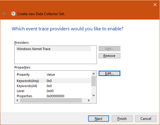
From the list shown in the Property window, select Automatic and check only net for Network TCP/IP, and then click OK.
Click Next to select a location where the files are saved. By default, this location is %SystemDrive%PerfLogsAdminexperiment, if this is how you named the data collector set. Click Next, and in the Run As edit box, enter the Administrator account name and set the password to match it. Click Finish. You should now see a window similar to the one shown here:
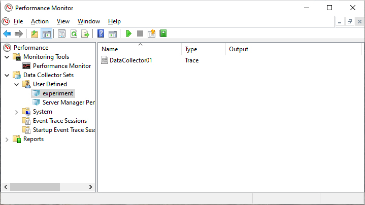
Right-click the name you gave your data collector set (experiment in our example), and then click Start. Now generate some network activity by opening a browser and visiting a website.
Right-click the data collector set node again and then click Stop.
xperf -on NETWORKTRACE -f c:
etwork.etl
The Global logger and Autologgers
Certain logger sessions start automatically when the system boots. The Global logger session records events that occur early in the operating system boot process, including events generated by the NT kernel logger. (The Global logger is actually a system logger, as shown in Table 10-16.) Applications and device drivers can use the Global logger session to capture traces before the user logs in (some device drivers, such as disk device drivers, are not loaded at the time the Global logger session begins.) While the Global logger is mostly used to capture traces produced by the NT kernel provider (see Table 10-17), Autologgers are designed to capture traces from classic ETW providers (and not from the NT kernel logger).
You can configure the Global logger by setting the proper registry values in the GlobalLogger key, which is located in the HKLMSYSTEMCurrentControlSetControlWMI root key. In the same way, Autologgers can be configured by creating a registry subkey, named as the logging session, in the Autologgers key (located in the WMI root key). The procedure for configuring and starting Autologgers is documented at https://docs.microsoft.com/en-us/windows/win32/etw/configuring-and-starting-an-Autologger-session.
As introduced in the “ETW initialization” section previously in this chapter, ETW starts the Global logger and Autologgers almost at the same time, during the early phase 1 of the NT kernel initialization. The EtwStartAutoLogger internal function queries all the logger configuration data from the registry, validates it, and creates the logger session using the EtwpStartLogger routine, which has already been extensively discussed in the “ETW sessions” section. The Global logger is a system logger, so after the session is created, no further providers are enabled. Unlike the Global logger, Autologgers require providers to be enabled. They are started by enumerating each session’s name from the Autologger registry key. After a session is created, ETW enumerates the providers that should be enabled in the session, which are listed as subkeys of the Autologger key (a provider is identified by a GUID). Figure 10-36 shows the multiple providers enabled in the EventLog-System session. This session is one of the main Windows Logs displayed by the Windows Event Viewer (captured by the Event Logger service).
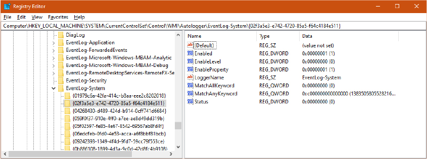
Figure 10-36 The EventLog-System Autologger’s enabled providers.
After the configuration data of a provider is validated, the provider is enabled in the session through the internal EtwpEnableTrace function, as for classic ETW sessions.
ETW security
Starting and stopping an ETW session is considered a high-privilege operation because events can include system data that can be used to exploit the system integrity (this is especially true for system loggers). The Windows Security model has been extended to support ETW security. As already introduced in previous sections, each operation performed by ETW requires a well-defined access right that must be granted by a security descriptor protecting the session, provider, or provider’s group (depending on the operation). Table 10-18 lists all the new access rights introduced for ETW and their usage.
Table 10-18 ETW security access rights and their usage
Value |
Description |
Applied to |
|---|---|---|
WMIGUID_QUERY |
Allows the user to query information about the trace session |
Session |
WMIGUID_NOTIFICATION |
Allows the user to send a notification to the session’s notification provider |
Session |
TRACELOG_CREATE_REALTIME |
Allows the user to start or update a real-time session |
Session |
TRACELOG_CREATE_ONDISK |
Allows the user to start or update a session that writes events to a log file |
Session |
TRACELOG_GUID_ENABLE |
Allows the user to enable the provider |
Provider |
TRACELOG_LOG_EVENT |
Allows the user to log events to a trace session if the session is running in SECURE mode |
Session |
TRACELOG_ACCESS_REALTIME |
Allows a consumer application to consume events in real time |
Session |
TRACELOG_REGISTER_GUIDS |
Allows the user to register the provider (creating the EtwRegistration object backed by the ETW_REG_ENTRY data structure) |
Provider |
TRACELOG_JOIN_GROUP |
Allows the user to insert a manifest-based or tracelogging provider to a Providers group (part of the ETW traits, which are not described in this book) |
Provider |
Most of the ETW access rights are automatically granted to the SYSTEM account and to members of the Administrators, Local Service, and Network Service groups. This implies that normal users are not allowed to interact with ETW (unless an explicit session and provider security descriptor allows it). To overcome the problem, Windows includes the Performance Log Users group, which has been designed to allow normal users to interact with ETW (especially for controlling trace sessions). Although all the ETW access rights are granted by the default security descriptor to the Performance Log Users group, Windows supports another group, called Performance Monitor Users, which has been designed only to receive or send notifications to the session notification provider. This is because the group has been designed to access system performance counters, enumerated by tools like Performance Monitor and Resource Monitor, and not to access the full ETW events. The two tools have been already described in the “Performance monitor and resource monitor” section of Chapter 1 in Part 1.
As previously introduced in the “ETW Sessions” section of this chapter, all the ETW security descriptors are stored in the HKLMSystemCurrentControlSetControlWmiSecurity registry key in a binary format. In ETW, everything that is represented by a GUID can be protected by a customized security descriptor. To manage ETW security, applications usually do not directly interact with security descriptors stored in the registry but use the EventAccessControl and EventAccessQuery APIs implemented in Sechost.dll.
Security Audit logger
The Security Audit logger is an ETW session used by the Windows Event logger service (wevtsvc.dll) to listen for events generated by the Security Lsass Provider. The Security Lsass provider (which is identified by the {54849625-5478-4994-a5ba-3e3b0328c30d} GUID) can be registered only by the NT kernel at ETW initialization time and is never inserted in the global provider’s hash table. Only the Security audit logger and Autologgers configured with the EnableSecurityProvider registry value set to 1 can receive events from the Security Lsass Provider. When the EtwStartAutoLogger internal function encounters the value set to 1, it enables the SECURITY_TRACE flag on the associated ETW session, adding the session to the list of loggers that can receive Security audit events.
The flag also has the important effect that user-mode applications can’t query, stop, flush, or control the session anymore, unless they are running as protected process light (at the antimalware, Windows, or WinTcb level; further details on protected processes are available in Chapter 3 of Part 1).
Secure loggers
Classic (MOF) and WPP providers have not been designed to support all the security features implemented for manifest-based and tracelogging providers. An Autologger or a generic ETW session can thus be created with the EVENT_TRACE_SECURE_MODE flag, which marks the session as secure. A secure session has the goal of ensuring that it receives events only from trusted identities. The flag has two main effects:
■ Prevents classic (MOF) and WPP providers from writing any event to the secure session. If a classic provider is enabled in a secure section, the provider won’t be able to generate any events.
■ Requires the supplemental TRACELOG_LOG_EVENT access right, which should be granted by the session’s security descriptor to the controller application’s access token while enabling a provider to the secure session.
The TRACE_LOG_EVENT access right allows a more-granular security to be specified in a session’s security descriptor. If the security descriptor grants only the TRACELOG_GUID_ENABLE to an untrusted user, and the ETW session is created as secure by another entity (a kernel driver or a more privileged application), the untrusted user can’t enable any provider on the secure section. If the section is created as nonsecure, the untrusted user can enable any providers on it.
Dynamic tracing (DTrace)
As discussed in the previous section, Event Tracing for Windows is a powerful tracing technology integrated into the OS, but it’s static, meaning that the end user can only trace and log events that are generated by well-defined components belonging to the operating system or to third-party frameworks/applications (.NET CLR, for example.) To overcome the limitation, the May 2019 Update of Windows 10 (19H1) introduced DTrace, the dynamic tracing facility built into Windows. DTrace can be used by administrators on live systems to examine the behavior of both user programs and of the operating system itself. DTrace is an open-source technology that was developed for the Solaris operating system (and its descendant, illumos, both of which are Unix-based) and ported to several operating systems other than Windows.
DTrace can dynamically trace parts of the operating system and user applications at certain locations of interest, called probes. A probe is a binary code location or activity to which DTrace can bind a request to perform a set of actions, like logging messages, recording a stack trace, a timestamp, and so on. When a probe fires, DTrace gathers the data from the probe and executes the actions associated with the probe. Both the probes and the actions are specified in a script file (or directly in the DTrace application through the command line), using the D programming language. Support for probes are provided by kernel modules, called providers. The original illumos DTrace supported around 20 providers, which were deeply tied to the Unix-based OS. At the time of this writing, Windows supports the following providers:
■ SYSCALL Allows the tracing of the OS system calls (both on entry and on exit) invoked from user-mode applications and kernel-mode drivers (through Zw* APIs).
■ FBT (Function Boundary tracing) Through FBT, a system administrator can trace the execution of individual functions implemented in all the modules that run in the NT kernel.
■ PID (User-mode process tracing) The provider is similar to FBT and allows tracing of individual functions of a user-mode process and application.
■ ETW (Event Tracing for Windows) DTrace can use this provider to attach to manifest-based and TraceLogging events fired from the ETW engine. DTrace is able to define new ETW providers and provide associated ETW events via the etw_trace action (which is not part of any provider).
■ PROFILE Provides probes associated with a time-based interrupt firing every fixed, specified time interval.
■ DTRACE Built-in provider is implicitly enabled in the DTrace engine.
The listed providers allow system administrators to dynamically trace almost every component of the Windows operating system and user-mode applications.
![]() Note
Note
There are big differences between the first version of DTrace for Windows, which appeared in the May 2019 Update of Windows 10, and the current stable release (distributed at the time of this writing in the May 2021 edition of Windows 10). One of the most notable differences is that the first release required a kernel debugger to be set up to enable the FBT provider. Furthermore, the ETW provider was not completely available in the first release of DTrace.
Internal architecture
As explained in the “Enabling DTrace and listing the installed providers” experiment earlier in this chapter, in Windows 10 May 2020 Update (20H1), some components of DTrace should be installed through an external package. Future versions of Windows may integrate DTrace completely in the OS image. Even though DTrace is deeply integrated in the operating system, it requires three external components to work properly. These include both the NT-specific implementation and the original DTrace code released under the free Common Development and Distribution License (CDDL), which is downloadable from https://github.com/microsoft/DTrace-on-Windows/tree/windows.
As shown in Figure 10-37, DTrace in Windows is composed of the following components:
■ DTrace.sys The DTrace extension driver is the main component that executes the actions associated with the probes and stores the results in a circular buffer that the user-mode application obtains via IOCTLs.
■ DTrace.dll The module encapsulates LibDTrace, which is the DTrace user-mode engine. It implements the Compiler for the D scripts, sends the IOCTLs to the DTrace driver, and is the main consumer of the circular DTrace buffer (where the DTrace driver stores the output of the actions).
■ DTrace.exe The entry point executable that dispatches all the possible commands (specified through the command line) to the LibDTrace.
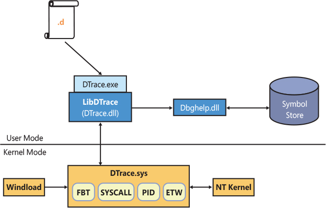
Figure 10-37 DTrace internal architecture.
To start the dynamic trace of the Windows kernel, a driver, or a user-mode application, the user just invokes the DTrace.exe main executable specifying a command or an external D script. In both cases, the command or the file contain one or more probes and additional actions expressed in the D programming language. DTrace.exe parses the input command line and forwards the proper request to the LibDTrace (which is implemented in DTrace.dll). For example, when started for enabling one or more probes, the DTrace executable calls the internal dtrace_program_fcompile function implemented in LibDTrace, which compiles the D script and produces the DTrace Intermediate Format (DIF) bytecode in an output buffer.
![]() Note
Note
Describing the details of the DIF bytecode and how a D script (or D commands) is compiled is outside the scope of this book. Interested readers can find detailed documentation in the OpenDTrace Specification book (released by the University of Cambridge), which is available at https://www.cl.cam.ac.uk/techreports/UCAM-CL-TR-924.pdf.
While the D compiler is entirely implemented in user-mode in LibDTrace, to execute the compiled DIF bytecode, the LibDtrace module just sends the DTRACEIOC_ENABLE IOCTL to the DTrace driver, which implements the DIF virtual machine. The DIF virtual machine is able to evaluate each D clause expressed in the bytecode and to execute optional actions associated with them. A limited set of actions are available, which are executed through native code and not interpreted via the D virtual machine.
As shown earlier in Figure 10-37, the DTrace extension driver implements all the providers. Before discussing how the main providers work, it is necessary to present an introduction of the DTrace initialization in the Windows OS.
DTrace initialization
The DTrace initialization starts in early boot stages, when the Windows loader is loading all the modules needed for the kernel to correctly start. One important part to load and validate is the API set file (apisetschema.dll), which is a key component of the Windows system. (API Sets are described in Chapter 3 of part 1.) If the DTRACE_ENABLED BCD element is set in the boot entry (value 0x26000145, which can be set through the dtrace readable name; see Chapter 12 for more details about BCD objects), the Windows loader checks whether the dtrace.sys driver is present in the %SystemRoot%System32Drivers path. If so, it builds a new API Set schema extension named ext-ms-win-ntos-trace-l1-1-0. The schema targets the Dtrace.sys driver and is merged into the system API set schema (OslApiSetSchema).
Later in the boot process, when the NT kernel is starting its phase 1 of initialization, the TraceInitSystem function is called to initialize the Dynamic Tracing subsystem. The API is imported in the NT kernel through the ext-ms-win-ntos-trace-l1-1-0.dll API set schema. This implies that if DTrace is not enabled by the Windows loader, the name resolution would fail, and the function will be basically a no op.
The TraceInitSystem has the important duty of calculating the content of the trace callouts array, which contains the functions that will be called by the NT kernel when a trace probe fires. The array is stored in the KiDynamicTraceCallouts global symbol, which will be later protected by Patchguard to prevent malicious drivers from illegally redirecting the flow of execution of system routines. Finally, through the TraceInitSystem function, the NT kernel sends to the DTrace driver another important array, which contains private system interfaces used by the DTrace driver to apply the probes. (The array is exposed in a trace extension context data structure.) This kind of initialization, where both the DTrace driver and the NT kernel exchange private interfaces, is the main motivation why the DTrace driver is called an extension driver.
The Pnp manager later starts the DTrace driver, which is installed in the system as boot driver, and calls its main entry point (DriverEntry). The routine registers the DeviceDTrace control device and its symbolic link (GLOBAL??DTrace). It then initializes the internal DTrace state, creating the first DTrace built-in provider. It finally registers all the available providers by calling the initialization function of each of them. The initialization method depends on each provider and usually ends up calling the internal dtrace_register function, which registers the provider with the DTrace framework. Another common action in the provider initialization is to register a handler for the control device. User-mode applications can communicate with DTrace and with a provider through the DTrace control device, which exposes virtual files (handlers) to providers. For example, the user-mode LibDTrace communicates directly with the PID provider by opening a handle to the \.DTraceFasttrap virtual file (handler).
The syscall provider
When the syscall provider gets activated, DTrace ends up calling the KeSetSystemServiceCallback routine, with the goal of activating a callback for the system call specified in the probe. The routine is exposed to the DTrace driver thanks to the NT system interfaces array. The latter is compiled by the NT kernel at DTrace initialization time (see the previous section for more details) and encapsulated in an extension context data structure internally called KiDynamicTraceContext. The first time that the KeSetSystemServiceCallback is called, the routine has the important task of building the global service trace table (KiSystemServiceTraceCallbackTable), which is an RB (red-black) tree containing descriptors of all the available syscalls. Each descriptor includes a hash of the syscall’s name, its address, and number of parameters and flags indicating whether the callback is enabled on entry or on exit. The NT kernel includes a static list of syscalls exposed through the KiServicesTab internal array.
After the global service trace table has been filled, the KeSetSystemServiceCallback calculates the hash of the syscall’s name specified by the probe and searches the hash in the RB tree. If there are no matches, the probe has specified a wrong syscall name (so the function exits signaling an error). Otherwise, the function modifies the enablement flags located in the found syscall’s descriptor and increases the number of the enabled trace callbacks (which is stored in an internal variable).
When the first DTrace syscall callback is enabled, the NT kernel sets the syscall bit in the global KiDynamicTraceMask bitmask. This is very important because it enables the system call handler (KiSystemCall64) to invoke the global trace handlers. (System calls and system service dispatching have been discussed extensively in Chapter 8.)
This design allows DTrace to coexist with the system call handling mechanism without having any sort of performance penalty. If no DTrace syscall probe is active, the trace handlers are not invoked. A trace handler can be called on entry and on exit of a system call. Its functionality is simple. It just scans the global service trace table looking for the descriptor of the system call. When it finds the descriptor, it checks whether the enablement flag is set and, if so, invokes the correct callout (contained in the global dynamic trace callout array, KiDynamicTraceCallouts, as specified in the previous section). The callout, which is implemented in the DTrace driver, uses the generic internal dtrace_probe function to fire the syscall probe and execute the actions associated with it.
The Function Boundary Tracing (FBT) and Process (PID) providers
Both the FBT and PID providers are similar because they allow a probe to be enabled on any function entry and exit points (not necessarily a syscall). The target function can reside in the NT kernel or as part of a driver (for these cases, the FBT provider is used), or it can reside in a user-mode module, which should be executed by a process. (The PID provider can trace user-mode applications.) An FBT or PID probe is activated in the system through breakpoint opcodes (INT 3 in x86, BRK in ARM64) that are written directly in the target function’s code. This has the following important implications:
■ When a PID or FBT probe raises, DTrace should be able to re-execute the replaced instruction before calling back the target function. To do this, DTrace uses an instruction emulator, which, at the time of this writing, is compatible with the AMD64 and ARM64 architecture. The emulator is implemented in the NT kernel and is normally invoked by the system exception handler while dealing with a breakpoint exception.
■ DTrace needs a way to identify functions by name. The name of a function is never compiled in the final binary (except for exported functions). DTrace uses multiple techniques to achieve this, which will be discussed in the “DTrace type library” section later in this chapter.
■ A single function can exit (return) in multiple ways from different code branches. To identify the exit points, a function graph analyzer is required to disassemble the function’s instructions and find each exit point. Even though the original function graph analyzer was part of the Solaris code, the Windows implementation of DTrace uses a new optimized version of it, which still lives in the LibDTrace library (DTrace.dll). While user-mode functions are analyzed by the function graph analyzer, DTrace uses the PDATA v2 unwind information to reliably find kernel-mode function exit points (more information on function unwinds and exception dispatching is available in Chapter 8). If the kernel-mode module does not make use of PDATA v2 unwind information, the FBT provider will not create any probes on function returns for it.
DTrace installs FBT or PID probes by calling the KeSetTracepoint function of the NT kernel exposed through the NT System interfaces array. The function validates the parameters (the callback pointer in particular) and, for kernel targets, verifies that the target function is located in an executable code section of a known kernel-mode module. Similar to the syscall provider, a KI_TRACEPOINT_ENTRY data structure is built and used for keeping track of the activated trace points. The data structure contains the owning process, access mode, and target function address. It is inserted in a global hash table, KiTpHashTable, which is allocated at the first time an FBT or PID probe gets activated. Finally, the single instruction located in the target code is parsed (imported in the emulator) and replaced with a breakpoint opcode. The trap bit in the global KiDynamicTraceMask bitmask is set.
For kernel-mode targets, the breakpoint replacement can happen only when VBS (Virtualization Based Security) is enabled. The MmWriteSystemImageTracepoint routine locates the loader data table entry associated with the target function and invokes the SECURESERVICE_SET_TRACEPOINT secure call. The Secure Kernel is the only entity able to collaborate with HyperGuard and thus to render the breakpoint application a legit code modification. As explained in Chapter 7 of Part 1, Kernel Patch protection (also known as Patchguard) prevents any code modification from being performed on the NT kernel and some essential kernel drivers. If VBS is not enabled on the system, and a debugger is not attached, an error code is returned, and the probe application fails. If a kernel debugger is attached, the breakpoint opcode is applied by the NT kernel through the MmDbgCopyMemory function. (Patchguard is not enabled on debugged systems.)
When called for debugger exceptions, which may be caused by a DTrace’s FTB or PID probe firing, the system exception handler (KiDispatchException) checks whether the “trap” bit is set in the global KiDynamicTraceMask bitmask. If it is, the exception handler calls the KiTpHandleTrap function, which searches into the KiTpHashTable to determine whether the exception occurred thanks to a registered FTB or PID probe firing. For user-mode probes, the function checks whether the process context is the expected one. If it is, or if the probe is a kernel-mode one, the function directly invokes the DTrace callback, FbtpCallback, which executes the actions associated with the probe. When the callback completes, the handler invokes the emulator, which emulates the original first instruction of the target function before transferring the execution context to it.
The ETW provider
DTrace supports both an ETW provider, which allows probes to fire when certain ETW events are generated by particular providers, and the etw_trace action, which allows DTrace scripts to generate new customized TraceLogging ETW events. The etw_trace action is implemented in LibDTrace, which uses TraceLogging APIs to dynamically register a new ETW provider and generate events associated with it. More information on ETW has been presented in the “Event Tracing for Windows (ETW)” section previously in this chapter.
The ETW provider is implemented in the DTrace driver. When the Trace engine is initialized by the Pnp manager, it registers all providers with the DTrace engine. At registration time, the ETW provider configures an ETW session called DTraceLoggingSession, which is set to write events in a circular buffer. When DTrace is started from the command line, it sends an IOCTL to DTrace driver. The IOCTL handler calls the provide function of each provider; the DtEtwpCreate internal function invokes the NtTraceControl API with the EtwEnumTraceGuidList function code. This allows DTrace to enumerate all the ETW providers registered in the system and to create a probe for each of them. (dtrace -l is also able to display ETW probes.)
When a D script targeting the ETW provider is compiled and executed, the internal DtEtwEnable routine gets called with the goal of enabling one or more ETW probes. The logging session configured at registration time is started, if it’s not already running. Through the trace extension context (which, as previously discussed, contains private system interfaces), DTrace is able to register a kernel-mode callback called every time a new event is logged in the DTrace logging session. The first time that the session is started, there are no providers associated with it. Similar to the syscall and FBT provider, for each probe DTrace creates a tracking data structure and inserts it in a global RB tree (DtEtwpProbeTree) representing all the enabled ETW probes. The tracking data structure is important because it represents the link between the ETW provider and the probes associated with it. DTrace calculates the correct enablement level and keyword bitmask for the provider (see the “Provider Enablement” section previously in this chapter for more details) and enables the provider in the session by invoking the NtTraceControl API.
When an event is generated, the ETW subsystem calls the callback routine, which searches into the global ETW probe tree the correct context data structure representing the probe. When found, DTrace can fire the probe (still using the internal dtrace_probe function) and execute all the actions associated with it.
DTrace type library
DTrace works with types. System administrators are able to inspect internal operating system data structures and use them in D clauses to describe actions associated with probes. DTrace also supports supplemental data types compared to the ones supported by the standard D programming language. To be able to work with complex OS-dependent data types and allow the FBT and PID providers to set probes on internal OS and application functions, DTrace obtains information from different sources:
■ Function names, signatures, and data types are initially extracted from information embedded in the executable binary (which adheres to the Portable Executable file format), like from the export table and debug information.
■ For the original DTrace project, the Solaris operating system included support for Compact C Type Format (CTF) in its executable binary files (which adhere to the Executable and Linkable Format - ELF). This allowed the OS to store the debug information needed by DTrace to run directly into its modules (the debug information can also be stored using the deflate compression format). The Windows version of DTrace still supports a partial CTF, which has been added as a resource section of the LibDTrace library (Dtrace.dll). CTF in the LibDTrace library stores the type information contained in the public WDK (Windows Driver Kit) and SDK (Software Development Kit) and allows DTrace to work with basic OS data types without requiring any symbol file.
■ Most of the private types and internal OS function signatures are obtained from PDB symbols. Public PDB symbols for the majority of the operating system’s modules are downloadable from the Microsoft Symbol Server. (These symbols are the same as those used by the Windows Debugger.) The symbols are deeply used by the FBT provider to correctly identify internal OS functions and by DTrace to be able to retrieve the correct type of parameters for each syscall and function.
The DTrace symbol server
DTrace includes an autonomous symbol server that can download PDB symbols from the Microsoft public Symbol store and render them available to the DTrace subsystem. The symbol server is implemented mainly in LibDTrace and can be queried by the DTrace driver using the Inverted call model. As part of the providers’ registration, the DTrace driver registers a SymServer pseudo-provider. The latter is not a real provider but just a shortcut for allowing the symsrv handler to the DTrace control device to be registered.
When DTrace is started from the command line, the LibDTrace library starts the symbols server by opening a handle to the \.dtracesymsrv control device (using the standard CreateFile API). The request is processed by the DTrace driver through the Symbol server IRP handler, which registers the user-mode process, adding it in an internal list of symbols server processes. LibDTrace then starts a new thread, which sends a dummy IOCTL to the DTrace symbol server device and waits indefinitely for a reply from the driver. The driver marks the IRP as pending and completes it only when a provider (or the DTrace subsystem), requires new symbols to be parsed.
Every time the driver completes the pending IRP, the DTrace symbols server thread wakes up and uses services exposed by the Windows Image Helper library (Dbghelp.dll) to correctly download and parse the required symbol. The driver then waits for a new dummy IOCTL to be sent from the symbols thread. This time the new IOCTL will contain the results of the symbol parsing process. The user-mode thread wakes up again only when the DTrace driver requires it.
Windows Error Reporting (WER)
Windows Error Reporting (WER) is a sophisticated mechanism that automates the submission of both user-mode process crashes as well as kernel-mode system crashes. Multiple system components have been designed for supporting reports generated when a user-mode process, protected process, trustlet, or the kernel crashes.
Windows 10, unlike from its predecessors, does not include a graphical dialog box in which the user can configure the details that Windows Error Reporting acquires and sends to Microsoft (or to an internal server configured by the system administrator) when an application crashes. As shown in Figure 10-38, in Windows 10, the Security and Maintenance applet of the Control Panel can show the user a history of the reports generated by Windows Error Reporting when an application (or the kernel) crashes. The applet can show also some basic information contained in the report.
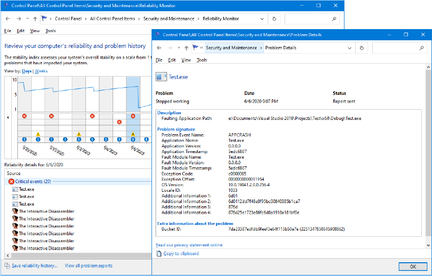
Figure 10-38 The Reliability monitor of the Security and Maintenance applet of the Control Panel.
Windows Error Reporting is implemented in multiple components of the OS, mainly because it needs to deal with different kind of crashes:
■ The Windows Error Reporting Service (WerSvc.dll) is the main service that manages the creation and sending of reports when a user-mode process, protected process, or trustlet crashes.
■ The Windows Fault Reporting and Secure Fault Reporting (WerFault.exe and WerFaultSecure.exe) are mainly used to acquire a snapshot of the crashing application and start the generation and sending of a report to the Microsoft Online Crash Analysis site (or, if configured, to an internal error reporting server).
■ The actual generation and transmission of the report is performed by the Windows Error Reporting Dll (Wer.dll). The library includes all the functions used internally by the WER engine and also some exported API that the applications can use to interact with Windows Error Reporting (documented at https://docs.microsoft.com/en-us/windows/win32/api/_wer/). Note that some WER APIs are also implemented in Kernelbase.dll and Faultrep.dll.
■ The Windows User Mode Crash Reporting DLL (Faultrep.dll) contains common WER stub code that is used by system modules (Kernel32.dll, WER service, and so on) when a user-mode application crashes or hangs. It includes services for creating a crash signature and reports a hang to the WER service, managing the correct security context for the report creation and transmission (which includes the creation of the WerFault executable under the correct security token).
■ The Windows Error Reporting Dump Encoding Library (Werenc.dll) is used by the Secure Fault Reporting to encrypt the dump files generated when a trustlet crashes.
■ The Windows Error Reporting Kernel Driver (WerKernel.sys) is a kernel library that exports functions to capture a live kernel memory dump and submit the report to the Microsoft Online Crash Analysis site. Furthermore, the driver includes APIs for creating and submitting reports for user-mode faults from a kernel-mode driver.
Describing the entire architecture of WER is outside the scope of this book. In this section, we mainly describe error reporting for user-mode applications and the NT kernel (or kernel-driver) crashes.
User applications crashes
As discussed in Chapter 3 of Part 1, all the user-mode threads in Windows start with the RtlUserThreadStart function located in Ntdll. The function does nothing more than calling the real thread start routine under a structured exception handler. (Structured exception handling is described in Chapter 8.) The handler protecting the real start routine is internally called Unhandled Exception Handler because it is the last one that can manage an exception happening in a user-mode thread (when the thread does not already handle it). The handler, if executed, usually terminates the process with the NtTerminateProcess API. The entity that decides whether to execute the handler is the unhandled exception filter, RtlpThreadExceptionFilter. Noteworthy is that the unhandled exception filter and handler are executed only under abnormal conditions; normally, applications should manage their own exceptions with inner exception handlers.
When a Win32 process is starting, the Windows loader maps the needed imported libraries. The kernelbase initialization routine installs its own unhandled exception filter for the process, the UnhandledExceptionFilter routine. When a fatal unhandled exception happens in a process’s thread, the filter is called to determine how to process the exception. The kernelbase unhandled exception filter builds context information (such as the current value of the machine’s registers and stack, the faulting process ID, and thread ID) and processes the exception:
■ If a debugger is attached to the process, the filter lets the exception happen (by returning CONTINUE_SEARCH). In this way, the debugger can break and see the exception.
■ If the process is a trustlet, the filter stops any processing and invokes the kernel to start the Secure Fault Reporting (WerFaultSecure.exe).
■ The filter calls the CRT unhandled exception routine (if it exists) and, in case the latter does not know how to handle the exception, it calls the internal WerpReportFault function, which connects to the WER service.
Before opening the ALPC connection, WerpReportFault should wake up the WER service and prepare an inheritable shared memory section, where it stores all the context information previously acquired. The WER service is a direct triggered-start service, which is started by the SCM only in case the WER_SERVICE_START WNF state is updated or in case an event is written in a dummy WER activation ETW provider (named Microsoft-Windows-Feedback-Service-Triggerprovider). WerpReportFault updates the relative WNF state and waits on the KernelObjectsSystemErrorPortReady event, which is signaled by the WER service to indicate that it is ready to accept new connections. After a connection has been established, Ntdll connects to the WER service’s WindowsErrorReportingServicePort ALPC port, sends the WERSVC_REPORT_CRASH message, and waits indefinitely for its reply.
The message allows the WER service to begin to analyze the crashed program’s state and performs the appropriate actions to create a crash report. In most cases, this means launching the WerFault.exe program. For user-mode crashes, the Windows Fault Reporting process is invoked two times using the faulting process’s credentials. The first time is used to acquire a “snapshot” of the crashing process. This feature was introduced in Windows 8.1 with the goal of rendering the crash report generation of UWP applications (which, at that time, were all single-instance applications) faster. In that way, the user could have restarted a crashed UWP application without waiting for the report being generated. (UWP and the modern application stack are discussed in Chapter 8.)
Snapshot creation
WerFault maps the shared memory section containing the crash data and opens the faulting process and thread. When invoked with the -pss command-line argument (used for requesting a process snapshot), it calls the PssNtCaptureSnapshot function exported by Ntdll. The latter uses native APIs to query multiple information regarding the crashing process (like basic information, job information, process times, secure mitigations, process file name, and shared user data section). Furthermore, the function queries information regarding all the memory sections baked by a file and mapped in the entire user-mode address space of the process. It then saves all the acquired data in a PSS_SNAPSHOT data structure representing a snapshot. It finally creates an identical copy of the entire VA space of the crashing process into another dummy process (cloned process) using the NtCreateProcessEx API (providing a special combination of flags). From now on, the original process can be terminated, and further operations needed for the report can be executed on the cloned process.
![]() Note
Note
WER does not perform any snapshot creation for protected processes and trustlets. In these cases, the report is generated by obtaining data from the original faulting process, which is suspended and resumed only after the report is completed.
Crash report generation
After the snapshot is created, execution control returns to the WER service, which initializes the environment for the crash report creation. This is done mainly in two ways:
■ If the crash happened to a normal, unprotected process, the WER service directly invokes the WerpInitiateCrashReporting routine exported from the Windows User Mode Crash Reporting DLL (Faultrep.dll).
■ Crashes belonging to protected processes need another broker process, which is spawned under the SYSTEM account (and not the faulting process credentials). The broker performs some verifications and calls the same routine used for crashes happening in normal processes.
The WerpInitiateCrashReporting routine, when called from the WER service, prepares the environment for executing the correct Fault Reporting process. It uses APIs exported from the WER library to initialize the machine store (which, in its default configuration, is located in C:ProgramDataMicrosoftWindowsWER) and load all the WER settings from the Windows registry. WER indeed contains many customizable options that can be configured by the user through the Group Policy editor or by manually making changes to the registry. At this stage, WER impersonates the user that has started the faulting application and starts the correct Fault Reporting process using the -u main command-line switch, which indicates to the WerFault (or WerFaultSecure) to process the user crash and create a new report.
![]() Note
Note
If the crashing process is a Modern application running under a low-integrity level or AppContainer token, WER uses the User Manager service to generate a new medium-IL token representing the user that has launched the faulting application.
Table 10-19 lists the WER registry configuration options, their use, and possible values. These values are located under the HKLMSOFTWAREMicrosoftWindowsWindows Error Reporting subkey for computer configuration and in the equivalent path under HKEY_CURRENT_USER for per-user configuration (some values can also be present in the SoftwarePoliciesMicrosoftWindowsWindows Error Reporting key).
Table 10-19 WER registry settings
Settings |
Meaning |
Values |
|---|---|---|
ConfigureArchive |
Contents of archived data |
1 for parameters, 2 for all data |
ConsentDefaultConsent |
What kind of data should require consent |
1 for any data, 2 for parameters only, 3 for parameters and safe data, 4 for all data. |
ConsentDefaultOverrideBehavior |
Whether the DefaultConsent overrides WER plug-in consent values |
1 to enable override |
ConsentPluginName |
Consent value for a specific WER plug-in |
Same as DefaultConsent |
CorporateWERDirectory |
Directory for a corporate WER store |
String containing the path |
CorporateWERPortNumber |
Port to use for a corporate WER store |
Port number |
CorporateWERServer |
Name to use for a corporate WER store |
String containing the name |
CorporateWERUseAuthentication |
Use Windows Integrated Authentication for corporate WER store |
1 to enable built-in authentication |
CorporateWERUseSSL |
Use Secure Sockets Layer (SSL) for corporate WER store |
1 to enable SSL |
DebugApplications |
List of applications that require the user to choose between Debug and Continue |
1 to require the user to choose |
DisableArchive |
Whether the archive is enabled |
1 to disable archive |
Disabled |
Whether WER is disabled |
1 to disable WER |
DisableQueue |
Determines whether reports are to be queued |
1 to disable queue |
DontShowUI |
Disables or enables the WER UI |
1 to disable UI |
DontSendAdditionalData |
Prevents additional crash data from being sent |
1 not to send |
ExcludedApplicationsAppName |
List of applications excluded from WER |
String containing the application list |
ForceQueue |
Whether reports should be sent to the user queue |
1 to send reports to the queue |
LocalDumpsDumpFolder |
Path at which to store the dump files |
String containing the path |
LocalDumpsDumpCount |
Maximum number of dump files in the path |
Count |
LocalDumpsDumpType |
Type of dump to generate during a crash |
0 for a custom dump, 1 for a minidump, 2 for a full dump |
LocalDumpsCustomDumpFlags |
For custom dumps, specifies custom options |
Values defined in MINIDUMP_TYPE (see Chapter 12 for more information) |
LoggingDisabled |
Enables or disables logging |
1 to disable logging |
MaxArchiveCount |
Maximum size of the archive (in files) |
Value between 1–5000 |
MaxQueueCount |
Maximum size of the queue |
Value between 1–500 |
QueuePesterInterval |
Days between requests to have the user check for solutions |
Number of days |
The Windows Fault Reporting process started with the -u switch starts the report generation: the process maps again the shared memory section containing the crash data, identifies the exception’s record and descriptor, and obtains the snapshot taken previously. In case the snapshot does not exist, the WerFault process operates directly on the faulting process, which is suspended. WerFault first determines the nature of the faulting process (service, native, standard, or shell process). If the faulting process has asked the system not to report any hard errors (through the SetErrorMode API), the entire process is aborted, and no report is created. Otherwise, WER checks whether a default post-mortem debugger is enabled through settings stored in the AeDebug subkey (AeDebugProtected for protected processes) under the HKLMSOFTWAREMicrosoftWindows NTCurrentVersion root registry key. Table 10-20 describes the possible values of both keys.
Table 10-20 Valid registry values used for the AeDebug and AeDebugProtected root keys
Value name |
Meaning |
Data |
|---|---|---|
Debugger |
Specify the debugger executable to be launched when an application crashes. |
Full path of the debugger executable, with eventual command-line arguments. The -p switch is automatically added by WER, pointing it to the crashing process ID. |
ProtectedDebugger |
Same as Debugger but for protected processes only. |
Full path of the debugger executable. Not valid for the AeDebug key. |
Auto |
Specify the Autostartup mode |
1 to enable the launching of the debugger in any case, without any user consent, 0 otherwise. |
LaunchNonProtected |
Specify whether the debugger should be executed as unprotected. This setting applies only to the AeDebugProtected key. |
1 to launch the debugger as a standard process. |
If the debugger start type is set to Auto, WER starts it and waits for a debugger event to be signaled before continuing the report creation. The report generation is started through the internal GenerateCrashReport routine implemented in the User Mode Crash Reporting DLL (Faultrep.dll). The latter configures all the WER plug-ins and initializes the report using the WerReportCreate API, exported from the WER.dll. (Note that at this stage, the report is only located in memory.) The GenerateCrashReport routine calculates the report ID and a signature and adds further diagnostics data to the report, like the process times and startup parameters or application-defined data. It then checks the WER configuration to determine which kind of memory dump to create (by default, a minidump is acquired). It then calls the exported WerReportAddDump API with the goal to initialize the dump acquisition for the faulting process (it will be added to the final report). Note that if a snapshot has been previously acquired, it is used for acquiring the dump.
The WerReportSubmit API, exported from WER.dll, is the central routine that generates the dump of the faulting process, creates all the files included in the report, shows the UI (if configured to do so by the DontShowUI registry value), and sends the report to the Online Crash server. The report usually includes the following:
■ A minidump file of the crashing process (usually named memory.hdmp)
■ A human-readable text report, which includes exception information, the calculated signature of the crash, OS information, a list of all the files associated with the report, and a list of all the modules loaded in the crashing process (this file is usually named report.wer)
■ A CSV (comma separated values) file containing a list of all the active processes at the time of the crash and basic information (like the number of threads, the private working set size, hard fault count, and so on)
■ A text file containing the global memory status information
■ A text file containing application compatibility information
The Fault Reporting process communicates through ALPC to the WER service and sends commands to allow the service to generate most of the information present in the report. After all the files have been generated, if configured appropriately, the Windows Fault Reporting process presents a dialog box (as shown in Figure 10-39) to the user, notifying that a critical error has occurred in the target process. (This feature is disabled by default in Windows 10.)
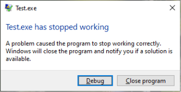
Figure 10-39 The Windows Error Reporting dialog box.
In environments where systems are not connected to the Internet or where the administrator wants to control which error reports are submitted to Microsoft, the destination for the error report can be configured to be an internal file server. The System Center Desktop Error Monitoring (part of the Microsoft Desktop Optimization Pack) understands the directory structure created by Windows Error Reporting and provides the administrator with the option to take selective error reports and submit them to Microsoft.
As previously discussed, the WER service uses an ALPC port for communicating with crashed processes. This mechanism uses a systemwide error port that the WER service registers through NtSetInformationProcess (which uses DbgkRegisterErrorPort). As a result, all Windows processes have an error port that is actually an ALPC port object registered by the WER service. The kernel and the unhandled exception filter in Ntdll use this port to send a message to the WER service, which then analyzes the crashing process. This means that even in severe cases of thread state damage, WER is still able to receive notifications and launch WerFault.exe to log the detailed information of the critical error in a Windows Event log (or to display a user interface to the user) instead of having to do this work within the crashing thread itself. This solves all the problems of silent process death: Users are notified, debugging can occur, and service administrators can see the crash event.
Kernel-mode (system) crashes
Before discussing how WER is involved when a kernel crashes, we need to introduce how the kernel records crash information. By default, all Windows systems are configured to attempt to record information about the state of the system before the Blue Screen of Death (BSOD) is displayed, and the system is restarted. You can see these settings by opening the System Properties tool in Control Panel (under System and Security, System, Advanced System Settings), clicking the Advanced tab, and then clicking the Settings button under Startup and Recovery. The default settings for a Windows system are shown in Figure 10-40.
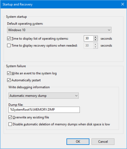
Figure 10-40 Crash dump settings.
Crash dump files
Different levels of information can be recorded on a system crash:
■ Active memory dump An active memory dump contains all physical memory accessible and in use by Windows at the time of the crash. This type of dump is a subset of the complete memory dump; it just filters out pages that are not relevant for troubleshooting problems on the host machine. This dump type includes memory allocated to user-mode applications and active pages mapped into the kernel or user space, as well as selected Pagefile-backed Transition, Standby, and Modified pages such as the memory allocated with VirtualAlloc or page-file backed sections. Active dumps do not include pages on the free and zeroed lists, the file cache, guest VM pages, and various other types of memory that are not useful during debugging.
■ Complete memory dump A complete memory dump is the largest kernel-mode dump file that contains all the physical pages accessible by Windows. This type of dump is not fully supported on all platforms (the active memory dump superseded it). Windows requires that a page file be at least the size of physical memory plus 1 MB for the header. Device drivers can add up to 256 548MB for secondary crash dump data, so to be safe, it’s recommended that you increase the size of the page file by an additional 256 MB.
■ Kernel memory dump A kernel memory dump includes only the kernel-mode pages allocated by the operating system, the HAL, and device drivers that are present in physical memory at the time of the crash. This type of dump does not contain pages belonging to user processes. Because only kernel-mode code can directly cause Windows to crash, however, it’s unlikely that user process pages are necessary to debug a crash. In addition, all data structures relevant for crash dump analysis—including the list of running processes, the kernel-mode stack of the current thread, and list of loaded drivers—are stored in nonpaged memory that saves in a kernel memory dump. There is no way to predict the size of a kernel memory dump because its size depends on the amount of kernel-mode memory allocated by the operating system and drivers present on the machine.
■ Automatic memory dump This is the default setting for both Windows client and server systems. An automatic memory dump is similar to a kernel memory dump, but it also saves some metadata of the active user-mode process (at the time of the crash). Furthermore, this dump type allows better management of the system paging file’s size. Windows can set the size of the paging file to less than the size of RAM but large enough to ensure that a kernel memory dump can be captured most of the time.
■ Small memory dump A small memory dump, which is typically between 128 KB and 1 MB in size and is also called a minidump or triage dump, contains the stop code and parameters, the list of loaded device drivers, the data structures that describe the current process and thread (called the EPROCESS and ETHREAD—described in Chapter 3 of Part 1), the kernel stack for the thread that caused the crash, and additional memory considered potentially relevant by crash dump heuristics, such as the pages referenced by processor registers that contain memory addresses and secondary dump data added by drivers.
![]() Note
Note
Device drivers can register a secondary dump data callback routine by calling KeRegisterBugCheckReasonCallback. The kernel invokes these callbacks after a crash and a callback routine can add additional data to a crash dump file, such as device hardware memory or device information for easier debugging. Up to 256 MB can be added systemwide by all drivers, depending on the space required to store the dump and the size of the file into which the dump is written, and each callback can add at most one-eighth of the available additional space. Once the additional space is consumed, drivers subsequently called are not offered the chance to add data.
The debugger indicates that it has limited information available to it when it loads a minidump, and basic commands like !process, which lists active processes, don’t have the data they need. A kernel memory dump includes more information, but switching to a different process’s address space mappings won’t work because required data isn’t in the dump file. While a complete memory dump is a superset of the other options, it has the drawback that its size tracks the amount of physical memory on a system and can therefore become unwieldy. Even though user-mode code and data usually are not used during the analysis of most crashes, the active memory dump overcame the limitation by storing in the dump only the memory that is actually used (excluding physical pages in the free and zeroed list). As a result, it is possible to switch address space in an active memory dump.
An advantage of a minidump is its small size, which makes it convenient for exchange via email, for example. In addition, each crash generates a file in the directory %SystemRoot%Minidump with a unique file name consisting of the date, the number of milliseconds that have elapsed since the system was started, and a sequence number (for example, 040712-24835-01.dmp). If there’s a conflict, the system attempts to create additional unique file names by calling the Windows GetTickCount function to return an updated system tick count, and it also increments the sequence number. By default, Windows saves the last 50 minidumps. The number of minidumps saved is configurable by modifying the MinidumpsCount value under the HKLMSYSTEMCurrentControlSetControl CrashControl registry key.
A significant disadvantage is that the limited amount of data stored in the dump can hamper effective analysis. You can also get the advantages of minidumps even when you configure a system to generate kernel, complete, active, or automatic crash dumps by opening the larger crash with WinDbg and using the .dump /m command to extract a minidump. Note that a minidump is automatically created even if the system is set for full or kernel dumps.
![]() Note
Note
You can use the .dump command from within LiveKd to generate a memory image of a live system that you can analyze offline without stopping the system. This approach is useful when a system is exhibiting a problem but is still delivering services, and you want to troubleshoot the problem without interrupting service. To prevent creating crash images that aren’t necessarily fully consistent because the contents of different regions of memory reflect different points in time, LiveKd supports the –m flag. The mirror dump option produces a consistent snapshot of kernel-mode memory by leveraging the memory manager’s memory mirroring APIs, which give a point-in-time view of the system.
The kernel memory dump option offers a practical middle ground. Because it contains all kernel-mode-owned physical memory, it has the same level of analysis-related data as a complete memory dump, but it omits the usually irrelevant user-mode data and code, and therefore can be significantly smaller. As an example, on a system running a 64-bit version of Windows with 4 GB of RAM, a kernel memory dump was 294 MB in size.
When you configure kernel memory dumps, the system checks whether the paging file is large enough, as described earlier. There isn’t a reliable way to predict the size of a kernel memory dump. The reason you can’t predict the size of a kernel memory dump is that its size depends on the amount of kernel-mode memory in use by the operating system and drivers present on the machine at the time of the crash. Therefore, it is possible that at the time of the crash, the paging file is too small to hold a kernel dump, in which case the system will switch to generating a minidump. If you want to see the size of a kernel dump on your system, force a manual crash either by configuring the registry option to allow you to initiate a manual system crash from the console (documented at https://docs.microsoft.com/en-us/windows-hardware/drivers/debugger/forcing-a-system-crash-from-the-keyboard) or by using the Notmyfault tool (https://docs.microsoft.com/en-us/sysinternals/downloads/notmyfault).
The automatic memory dump overcomes this limitation, though. The system will be indeed able to create a paging file large enough to ensure that a kernel memory dump can be captured most of the time. If the computer crashes and the paging file is not large enough to capture a kernel memory dump, Windows increases the size of the paging file to at least the size of the physical RAM installed.
To limit the amount of disk space that is taken up by crash dumps, Windows needs to determine whether it should maintain a copy of the last kernel or complete dump. After reporting the kernel fault (described later), Windows uses the following algorithm to decide whether it should keep the Memory.dmp file. If the system is a server, Windows always stores the dump file. On a Windows client system, only domain-joined machines will always store a crash dump by default. For a non-domain-joined machine, Windows maintains a copy of the crash dump only if there is more than 25 GB of free disk space on the destination volume (4 GB on ARM64, configurable via the HKLMSYSTEMCurrentControlSetControlCrashControlPersistDumpDiskSpaceLimit registry value)—that is, the volume where the system is configured to write the Memory.dmp file. If the system, due to disk space constraints, is unable to keep a copy of the crash dump file, an event is written to the System event log indicating that the dump file was deleted, as shown in Figure 10-41. This behavior can be overridden by creating the DWORD registry value HKLMSYSTEMCurrentControlSetControlCrashControlAlwaysKeepMemoryDump and setting it to 1, in which case Windows always keeps a crash dump, regardless of the amount of free disk space.
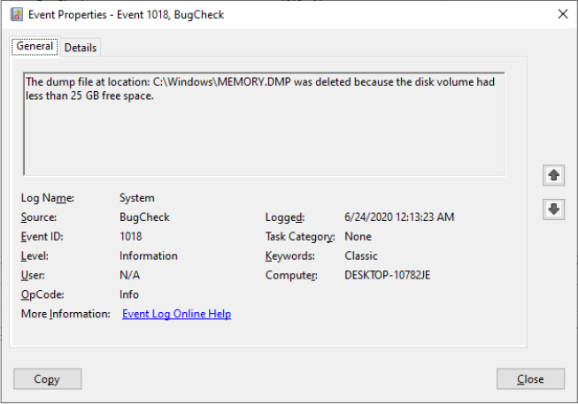
Figure 10-41 Dump file deletion event log entry.
Crash dump generation
Phase 1 of the system boot process allows the I/O manager to check the configured crash dump options by reading the HKLMSYSTEMCurrentControlSetControlCrashControl registry key. If a dump is configured, the I/O manager loads the crash dump driver (Crashdmp.sys) and calls its entry point. The entry point transfers back to the I/O manager a table of control functions, which are used by the I/O manager for interacting with the crash dump driver. The I/O manager also initializes the secure encryption needed by the Secure Kernel to store the encrypted pages in the dump. One of the control functions in the table initializes the global crash dump system. It gets the physical sectors (file extent) where the page file is stored and the volume device object associated with it.
The global crash dump initialization function obtains the miniport driver that manages the physical disk in which the page file is stored. It then uses the MmLoadSystemImageEx routine to make a copy of the crash dump driver and the disk miniport driver, giving them their original names prefixed by the dump_ string. Note that this implies also creating a copy of all the drivers imported by the miniport driver, as shown in the Figure 10-42.
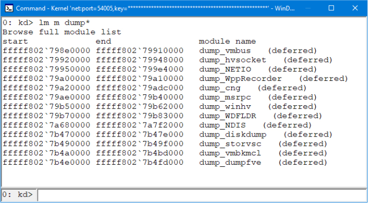
Figure 10-42 Kernel modules copied for use to generate and write a crash dump file.
The system also queries the DumpFilters value for any filter drivers that are required for writing to the volume, an example being Dumpfve.sys, the BitLocker Drive Encryption Crashdump Filter driver. It also collects information related to the components involved with writing a crash dump—including the name of the disk miniport driver, the I/O manager structures that are necessary to write the dump, and the map of where the paging file is on disk—and saves two copies of the data in dump-context structures. The system is ready to generate and write a dump using a safe, noncorrupted path.
Indeed, when the system crashes, the crash dump driver (%SystemRoot%System32DriversCrashdmp.sys) verifies the integrity of the two dump-context structures obtained at boot by performing a memory comparison. If there’s not a match, it does not write a crash dump because doing so would likely fail or corrupt the disk. Upon a successful verification match, Crashdmp.sys, with support from the copied disk miniport driver and any required filter drivers, writes the dump information directly to the sectors on disk occupied by the paging file, bypassing the file system driver and storage driver stack (which might be corrupted or even have caused the crash).
![]() Note
Note
Because the page file is opened early during system startup for crash dump use, most crashes that are caused by bugs in system-start driver initialization result in a dump file. Crashes in early Windows boot components such as the HAL or the initialization of boot drivers occur too early for the system to have a page file, so using another computer to debug the startup process is the only way to perform crash analysis in those cases.
During the boot process, the Session Manager (Smss.exe) checks the registry value HKLMSYSTEMCurrentControlSetControlSession ManagerMemory ManagementExistingPageFiles for a list of existing page files from the previous boot. (See Chapter 5 of Part 1 for more information on page files.) It then cycles through the list, calling the function SmpCheckForCrashDump on each file present, looking to see whether it contains crash dump data. It checks by searching the header at the top of each paging file for the signature PAGEDUMP or PAGEDU64 on 32-bit or 64-bit systems, respectively. (A match indicates that the paging file contains crash dump information.) If crash dump data is present, the Session Manager then reads a set of crash parameters from the HKLMSYSTEMCurrentControlSetControlCrashControl registry key, including the DumpFile value that contains the name of the target dump file (typically %SystemRoot%Memory.dmp, unless configured otherwise).
Smss.exe then checks whether the target dump file is on a different volume than the paging file. If so, it checks whether the target volume has enough free disk space (the size required for the crash dump is stored in the dump header of the page file) before truncating the paging file to the size of the crash data and renaming it to a temporary dump file name. (A new page file will be created later when the Session Manager calls the NtCreatePagingFile function.) The temporary dump file name takes the format DUMPxxxx.tmp, where xxxx is the current low-word value of the system’s tick count (The system attempts 100 times to find a nonconflicting value.) After renaming the page file, the system removes both the hidden and system attributes from the file and sets the appropriate security descriptors to secure the crash dump.
Next, the Session Manager creates the volatile registry key HKLMSYSTEMCurrentControlSetControlCrashControlMachineCrash and stores the temporary dump file name in the value DumpFile. It then writes a DWORD to the TempDestination value indicating whether the dump file location is only a temporary destination. If the paging file is on the same volume as the destination dump file, a temporary dump file isn’t used because the paging file is truncated and directly renamed to the target dump file name. In this case, the DumpFile value will be that of the target dump file, and TempDestination will be 0.
Later in the boot, Wininit checks for the presence of the MachineCrash key, and if it exists, launches the Windows Fault Reporting process (Werfault.exe) with the -k -c command-line switches (the k flag indicates kernel error reporting, and the c flag indicates that the full or kernel dump should be converted to a minidump). WerFault reads the TempDestination and DumpFile values. If the TempDestination value is set to 1, which indicates a temporary file was used, WerFault moves the temporary file to its target location and secures the target file by allowing only the System account and the local Administrators group access. WerFault then writes the final dump file name to the FinalDumpFileLocation value in the MachineCrash key. These steps are shown in Figure 10-43.
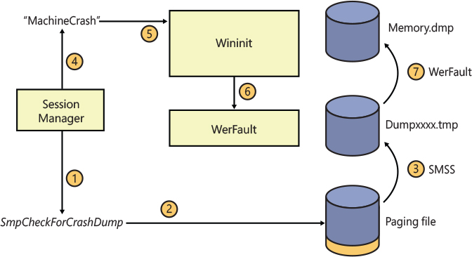
Figure 10-43 Crash dump file generation.
To provide more control over where the dump file data is written to—for example, on systems that boot from a SAN or systems with insufficient disk space on the volume where the paging file is configured—Windows also supports the use of a dedicated dump file that is configured in the DedicatedDumpFile and DumpFileSize values under the HKLMSYSTEMCurrentControlSetControlCrashControl registry key. When a dedicated dump file is specified, the crash dump driver creates the dump file of the specified size and writes the crash data there instead of to the paging file. If no DumpFileSize value is given, Windows creates a dedicated dump file using the largest file size that would be required to store a complete dump. Windows calculates the required size as the size of the total number of physical pages of memory present in the system plus the size required for the dump header (one page on 32-bit systems, and two pages on 64-bit systems), plus the maximum value for secondary crash dump data, which is 256 MB. If a full or kernel dump is configured but there is not enough space on the target volume to create the dedicated dump file of the required size, the system falls back to writing a minidump.
Kernel reports
After the WerFault process is started by Wininit and has correctly generated the final dump file, WerFault generates the report to send to the Microsoft Online Crash Analysis site (or, if configured, an internal error reporting server). Generating a report for a kernel crash is a procedure that involves the following:
If the type of dump generated was not a minidump, it extracts a minidump from the dump file and stores it in the default location of %SystemRoot%Minidump, unless otherwise configured through the MinidumpDir value in the HKLMSYSTEMCurrentControlSetControlCrashControl key.
It writes the name of the minidump files to HKLMSOFTWAREMicrosoftWindowsWindows Error ReportingKernelFaultsQueue.
It adds a command to execute WerFault.exe (%SystemRoot%System32WerFault.exe) with the –k –rq flags (the rq flag specifies to use queued reporting mode and that WerFault should be restarted) to HKLMSOFTWAREMicrosoftWindowsCurrentVersionRunOnce so that WerFault is executed during the first user’s logon to the system for purposes of actually sending the error report.
When the WerFault utility executes during logon, as a result of having configured itself to start, it launches itself again using the –k –q flags (the q flag on its own specifies queued reporting mode) and terminates the previous instance. It does this to prevent the Windows shell from waiting on WerFault by returning control to RunOnce as quickly as possible. The newly launched WerFault.exe checks the HKLMSOFTWAREMicrosoftWindowsWindows Error ReportingKernelFaultsQueue key to look for queued reports that may have been added in the previous dump conversion phase. It also checks whether there are previously unsent crash reports from previous sessions. If there are, WerFault.exe generates two XML-formatted files:
■ The first contains a basic description of the system, including the operating system version, a list of drivers installed on the machine, and the list of devices present in the system.
■ The second contains metadata used by the OCA service, including the event type that triggered WER and additional configuration information, such as the system manufacturer.
WerFault then sends a copy of the two XML files and the minidump to Microsoft OCA server, which forwards the data to a server farm for automated analysis. The server farm’s automated analysis uses the same analysis engine that the Microsoft kernel debuggers use when you load a crash dump file into them. The analysis generates a bucket ID, which is a signature that identifies a particular crash type.
Process hang detection
Windows Error reporting is also used when an application hangs and stops work because of some defect or bug in its code. An immediate effect of an application hanging is that it would not react to any user interaction. The algorithm used for detecting a hanging application depends on the application type: the Modern application stack detects that a Centennial or UWP application is hung when a request sent from the HAM (Host Activity Manager) is not processed after a well-defined timeout (usually 30 seconds); the Task manager detects a hung application when an application does not reply to the WM_QUIT message; Win32 desktop applications are considered not responding and hung when a foreground window stops to process GDI messages for more than 5 seconds.
Describing all the hung detection algorithms is outside the scope of this book. Instead, we will consider the most likely case of a classical Win32 desktop application that stopped to respond to any user input. The detection starts in the Win32k kernel driver, which, after the 5-second timeout, sends a message to the DwmApiPort ALPC port created by the Desktop Windows Manager (DWM.exe). The DWM processes the message using a complex algorithm that ends up creating a “ghost” window on top of the hanging window. The ghost redraws the window’s original content, blurring it out and adding the (Not Responding) string in the title. The ghost window processes GDI messages through an internal message pump routine, which intercepts the close, exit, and activate messages by calling the ReportHang routine exported by the Windows User Mode Crash Reporting DLL (faultrep.dll). The ReportHang function simply builds a WERSVC_REPORT_HANG message and sends it to the WER service to wait for a reply.
The WER service processes the message and initializes the Hang reporting by reading settings values from the HKLMSoftwareMicrosoftWindowsWindows Error ReportingHangs root registry key. In particular, the MaxHangrepInstances value is used to indicate how many hanging reports can be generated in the same time (the default number is eight if the value does not exist), while the TerminationTimeout value specifies the time that needs to pass after WER has tried to terminate the hanging process before considering the entire system to be in hanging situation (10 seconds by default). This situation can happen for various reasons—for example, an application has an active pending IRP that is never completed by a kernel driver. The WER service opens the hanging process and obtains its token, and some other basic information. It then creates a shared memory section object to store them (similar to user application crashes; in this case, the shared section has a name: Global<Random GUID>).
A WerFault process is spawned in a suspended state using the faulting process’s token and the -h command-line switch (which is used to specify to generate a report for a hanging process). Unlike with user application crashes, a snapshot of the hanging process is taken from the WER service using a full SYSTEM token by invoking the the PssNtCaptureSnapshot API exported in Ntdll. The snapshot’s handle is duplicated in the suspended WerFault process, which is resumed after the snapshot has been successfully acquired. When the WerFault starts, it signals an event indicating that the report generation has started. From this stage, the original process can be terminated. Information for the report is grabbed from the cloned process.
The report for a hanging process is similar to the one acquired for a crashing process: The WerFault process starts by querying the value of the Debugger registry value located in the global HKLMSoftwareMicrosoftWindowsWindows Error ReportingHangs root registry key. If there is a valid debugger, it is launched and attached to the original hanging process. In case the Disable registry value is set to 1, the procedure is aborted and the WerFault process exits without generating any report. Otherwise, WerFault opens the shared memory section, validates it, and grabs all the information previously saved by the WER service. The report is initialized by using the WerReportCreate function exported in WER.dll and used also for crashing processes. The dialog box for a hanging process (shown in Figure 10-44) is always displayed independently on the WER configuration. Finally, the WerReportSubmit function (exported in WER.dll) is used to generate all the files for the report (including the minidump file) similarly to user applications crashes (see the “Crash report generation” section earlier in this chapter). The report is finally sent to the Online Crash Analysis server.
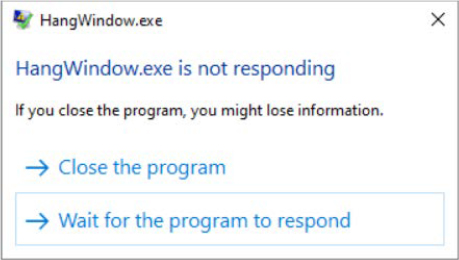
Figure 10-44 The Windows Error Reporting dialog box for hanging applications.
After the report generation is started and the WERSVC_HANG_REPORTING_STARTED message is returned to DWM, WER kills the hanging process using the TerminateProcess API. If the process is not terminated in an expected time frame (generally 10 seconds, but customizable through the TerminationTimeout setting as explained earlier), the WER service relaunches another WerFault instance running under a full SYSTEM token and waits another longer timeout (usually 60 seconds but customizable through the LongTerminationTimeout setting). If the process is not terminated even by the end of the longer timeout, WER has no other chances than to write an ETW event on the Application event log, reporting the impossibility to terminate the process. The ETW event is shown in Figure 10-45. Note that the event description is misleading because WER hasn’t been able to terminate the hanging application.

Figure 10-45 ETW error event written to the Application log for a nonterminating hanging application.
Global flags
Windows has a set of flags stored in two systemwide global variables named NtGlobalFlag and NtGlobalFlag2 that enable various internal debugging, tracing, and validation support in the operating system. The two system variables are initialized from the registry key HKLMSYSTEMCurrentControlSetControlSession Manager in the values GlobalFlag and GlobalFlag2 at system boot time (phase 0 of the NT kernel initialization). By default, both registry values are 0, so it’s likely that on your systems, you’re not using any global flags. In addition, each image has a set of global flags that also turn on internal tracing and validation code (although the bit layout of these flags is slightly different from the systemwide global flags).
Fortunately, the debugging tools contain a utility named Gflags.exe that you can use to view and change the system global flags (either in the registry or in the running system) as well as image global flags. Gflags has both a command-line and a GUI interface. To see the command-line flags, type gflags /?. If you run the utility without any switches, the dialog box shown in Figure 10-46 is displayed.
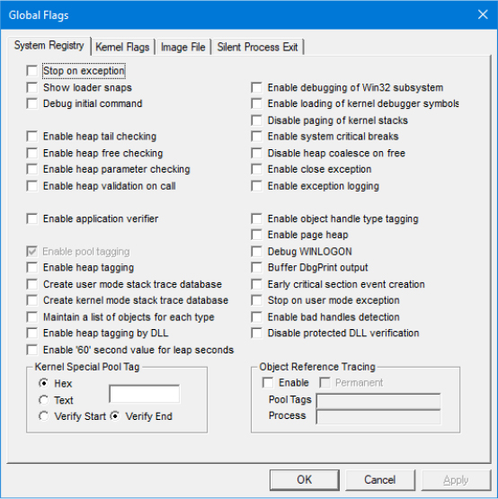
Figure 10-46 Setting system debugging options with GFlags.
Flags belonging to the Windows Global flags variables can be split in different categories:
■ Kernel flags are processed directly by various components of the NT kernel (the heap manager, exceptions, interrupts handlers, and so on).
■ User flags are processed by components running in user-mode applications (usually Ntdll).
■ Boot-only flags are processed only when the system is starting.
■ Per-image file global flags (which have a slightly different meaning than the others) are processed by the loader, WER, and some other user-mode components, depending on the user-mode process context in which they are running.
The names of the group pages shown by the GFlags tool is a little misleading. Kernel, boot-only, and user flags are mixed together in each page. The main difference is that the System Registry page allows the user to set global flags on the GlobalFlag and GlobalFlag2 registry values, parsed at system boot time. This implies that eventual new flags will be enabled only after the system is rebooted. The Kernel Flags page, despite its name, does not allow kernel flags to be applied on the fly to a live system. Only certain user-mode flags can be set or removed (the enable page heap flag is a good example) without requiring a system reboot: the Gflags tool sets those flags using the NtSetSystemInformation native API (with the SystemFlagsInformation information class). Only user-mode flags can be set in that way.
The Image File page requires you to fill in the file name of an executable image. Use this option to change a set of global flags that apply to an individual image (rather than to the whole system). The page is shown in Figure 10-47. Notice that the flags are different from the operating system ones shown in Figure 10-46. Most of the flags and the setting available in the Image File and Silent Process Exit pages are applied by storing new values in a subkey with the same name as the image file (that is, notepad.exe for the case shown in Figure 10-47) under the HKLMSOFTWAREMicrosoftWindows NTCurrentVersionImage File Execution Options registry key (also known as the IFEO key). In particular, the GlobalFlag (and GlobalFlag2) value represents a bitmask of all the available per-image global flags.
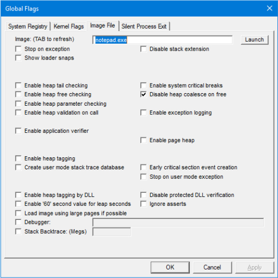
Figure 10-47 Setting per-image global flags with GFlags.
When the loader initializes a new process previously created and loads all the dependent libraries of the main base executable (see Chapter 3 of Part 1 for more details about the birth of a process), the system processes the per-image global flags. The LdrpInitializeExecutionOptions internal function opens the IFEO key based on the name of the base image and parses all the per-image settings and flags. In particular, after the per-image global flags are retrieved from the registry, they are stored in the NtGlobalFlag (and NtGlobalFlag2) field of the process PEB. In this way, they can be easily accessed by any image mapped in the process (including Ntdll).
Most of the available global flags are documented at https://docs.microsoft.com/en-us/windows-hardware/drivers/debugger/gflags-flag-table.
Kernel shims
New releases of the Windows operating system can sometime bring issues with old drivers, which can have difficulties in operating in the new environment, producing system hangs or blue screens of death. To overcome the problem, Windows 8.1 introduced a Kernel Shim engine that’s able to dynamically modify old drivers, which can continue to run in the new OS release. The Kernel Shim engine is implemented mainly in the NT kernel. Driver’s shims are registered through the Windows Registry and the Shim Database file. Drivers’ shims are provided by shim drivers. A shim driver uses the exported KseRegisterShimEx API to register a shim that can be applied to target drivers that need it. The Kernel Shim engine supports mainly two kinds of shims applied to devices or drivers.
Shim engine initialization
In early OS boot stages, the Windows Loader, while loading all the boot-loaded drivers, reads and maps the driver compatibility database file, located in %SystemRoot%apppatchDrvmain.sdb (and, if it exists, also in the Drvpatch.sdb file). In phase 1 of the NT kernel initialization, the I/O manager starts the two phases of the Kernel Shim engine initialization. The NT kernel copies the binary content of the database file(s) in a global buffer allocated from the paged pool (pointed by the internal global KsepShimDb variable). It then checks whether Kernel Shims are globally disabled. In case the system has booted in Safe or WinPE mode, or in case Driver verifier is enabled, the shim engine wouldn’t be enabled. The Kernel Shim engine is controllable also using system policies or through the HKLMSystemCurrentControlSetControlCompatibilityDisableFlags registry value. The NT kernel then gathers low-level system information needed when applying device shims, like the BIOS information and OEM ID, by checking the System Fixed ACPI Descriptor Table (FADT). The shim engine registers the first built-in shim provider, named DriverScope, using the KseRegisterShimEx API. Built-in shims provided by Windows are listed in Table 10-21. Some of them are indeed implemented in the NT kernel directly and not in any external driver. DriverScope is the only shim registered in phase 0.
Table 10-21 Windows built-in kernel shims
Shim Name |
GUID |
Purpose |
Module |
|---|---|---|---|
DriverScope |
{BC04AB45-EA7E-4A11-A7BB-977615F4CAAE} |
The driver scope shim is used to collect health ETW events for a target driver. Its hooks do nothing other than writing an ETW event before or after calling the original nonshimmed callbacks. |
NT kernel |
Version Lie |
{3E28B2D1-E633-408C-8E9B-2AFA6F47FCC3} (7.1) (47712F55-BD93-43FC-9248-B9A83710066E} (8) {21C4FB58-D477-4839-A7EA-AD6918FBC518} (8.1) |
The version lie shim is available for Windows 7, 8, and 8.1. The shim communicates a previous version of the OS when required by a driver in which it is applied. |
NT kernel |
SkipDriverUnload |
{3E8C2CA6-34E2-4DE6-8A1E-9692DD3E316B} |
The shim replaces the driver’s unload routine with one that doesn’t do anything except logging an ETW event. |
NT kernel |
ZeroPool |
{6B847429-C430-4682-B55F-FD11A7B55465} |
Replace the ExAllocatePool API with a function that allocates the pool memory and zeroes it out. |
NT kernel |
ClearPCIDBits |
{B4678DFF-BD3E-46C9-923B-B5733483B0B3} |
Clear the PCID bits when some antivirus drivers are mapping physical memory referred by CR3. |
NT kernel |
Kaspersky |
{B4678DFF-CC3E-46C9-923B-B5733483B0B3} |
Shim created for specific Kaspersky filter drivers for masking the real value of the UseVtHardware registry value, which could have caused bug checks on old versions of the antivirus. |
NT kernel |
Memcpy |
{8A2517C1-35D6-4CA8-9EC8-98A12762891B} |
Provides a safer (but slower) memory copy implementation that always zeroes out the destination buffer and can be used with device memory. |
NT kernel |
KernelPadSectionsOverride |
{4F55C0DB-73D3-43F2-9723-8A9C7F79D39D} |
Prevents discardable sections of any kernel module to be freed by the memory manager and blocks the loading of the target driver (where the shim is applied). |
NT kernel |
NDIS Shim |
{49691313-1362-4e75-8c2a-2dd72928eba5} |
NDIS version compatibility shim (returns 6.40 where applied to a driver). |
Ndis.sys |
SrbShim |
{434ABAFD-08FA-4c3d-A88D-D09A88E2AB17} |
SCSI Request Block compatibility shim that intercepts the IOCTL_STORAGE_QUERY_PROPERTY. |
Storport.sys |
DeviceIdShim |
{0332ec62-865a-4a39-b48f-cda6e855f423} |
Compatibility shim for RAID devices. |
Storport.sys |
ATADeviceIdShim |
{26665d57-2158-4e4b-a959-c917d03a0d7e} |
Compatibility shim for serial ATA devices. |
Storport.sys |
Bluetooth Filter Power shim |
{6AD90DAD-C144-4E9D-A0CF-AE9FCB901EBD} |
Compatibility shim for Bluetooth filter drivers. |
Bthport.sys |
UsbShim |
{fd8fd62e-4d94-4fc7-8a68-bff7865a706b} |
Compatibility shim for old Conexant USB modem. |
Usbd.sys |
Nokia Usbser Filter Shim |
{7DD60997-651F-4ECB-B893-BEC8050F3BD7} |
Compatibility shim for Nokia Usbser filter drivers (used by Nokia PC Suite). |
Usbd.sys |
A shim is internally represented through the KSE_SHIM data structure (where KSE stands for Kernel Shim Engine). The data structure includes the GUID, the human-readable name of the shim, and an array of hook collection (KSE_HOOK_COLLECTION data structures). Driver shims support different kinds of hooks: hooks on functions exported by the NT kernel, HAL, and by driver libraries, and on driver’s object callback functions. In phase 1 of its initialization, the Shim Engine registers the Microsoft-Windows-Kernel-ShimEngine ETW provider (which has the {0bf2fb94-7b60-4b4d-9766-e82f658df540} GUID), opens the driver shim database, and initializes the remaining built-in shims implemented in the NT kernel (refer to Table 10-21).
To register a shim (through KseRegisterShimEx), the NT kernel performs some initial integrity checks on both the KSE_SHIM data structure, and each hook in the collection (all the hooks must reside in the address space of the calling driver). It then allocates and fills a KSE_REGISTERED_SHIM_ENTRY data structure which, as the name implies, represents the registered shim. It contains a reference counter and a pointer back to the driver object (used only in case the shim is not implemented in the NT kernel). The allocated data structure is linked in a global linked list, which keeps track of all the registered shims in the system.
The shim database
The shim database (SDB) file format was first introduced in the old Windows XP for Application Compatibility. The initial goal of the file format was to store a binary XML-style database of programs and drivers that needed some sort of help from the operating system to work correctly. The SDB file has been adapted to include kernel-mode shims. The file format describes an XML database using tags. A tag is a 2-byte basic data structure used as unique identifier for entries and attributes in the database. It is made of a 4-bit type, which identifies the format of the data associated with the tag, and a 12-bit index. Each tag indicates the data type, size, and interpretation that follows the tag itself. An SDB file has a 12-byte header and a set of tags. The set of tags usually defines three main blocks in the shim database file:
■ The INDEX block contains index tags that serve to fast-index elements in the database. Indexes in the INDEX block are stored in increasing order. Therefore, searching an element in the indexes is a fast operation (using a binary search algorithm). For the Kernel Shim engine, the elements are stored in the INDEXES block using an 8-byte key derived from the shim name.
■ The DATABASE block contains top-level tags describing shims, drivers, devices, and executables. Each top-level tag contains children tags describing properties or inner blocks belonging to the root entity.
■ The STRING TABLE block contains strings that are referenced by lower-level tags in the DATABASE block. Tags in the DATABASE block usually do not directly describe a string but instead contain a reference to a tag (called STRINGREF) describing a string located in the string table. This allows databases that contain a lot of common strings to be small in size.
Microsoft has partially documented the SDB file format and the APIs used to read and write it at https://docs.microsoft.com/en-us/windows/win32/devnotes/application-compatibility-database. All the SDB APIs are implemented in the Application Compatibility Client Library (apphelp.dll).
Driver shims
The NT memory manager decides whether to apply a shim to a kernel driver at its loading time, using the KseDriverLoadImage function (boot-loaded drivers are processed by the I/O manager, as discussed in Chapter 12). The routine is called at the correct time of a kernel-module life cycle, before either Driver Verifier, Import Optimization, or Kernel Patch protection are applied to it. (This is important; otherwise, the system would bugcheck.) A list of the current shimmed kernel modules is stored in a global variable. The KsepGetShimsForDriver routine checks whether a module in the list with the same base address as the one being loaded is currently present. If so, it means that the target module has already been shimmed, so the procedure is aborted. Otherwise, to determine whether the new module should be shimmed, the routine checks two different sources:
■ Queries the “Shims” multistring value from a registry key named as the module being loaded and located in the HKLMSystemCurrentControlSetControlCompatibilityDriver root key. The registry value contains an array of shims’ names that would be applied to the target module.
■ In case the registry value for a target module does not exist, parses the driver compatibility database file, looking for a KDRIVER tag (indexed by the INDEX block), which has the same name as the module being loaded. If a driver is found in the SDB file, the NT kernel performs a comparison of the driver version (TAG_SOURCE_OS stored in the KDRIVER root tag), file name, and path (if the relative tags exist in the SDB), and of the low-level system information gathered at engine initialization time (to determine if the driver is compatible with the system). In case any of the information does not match, the driver is skipped, and no shims are applied. Otherwise, the shim names list is grabbed from the KSHIM_REF lower-level tags (which is part of the root KDRIVER). The tags are reference to the KSHIMs located in the SDB database block.
If one of the two sources yields one or more shims names to be applied to the target driver, the SDB file is parsed again with the goal to validate that a valid KSHIM descriptor exists. If there are no tags related to the specified shim name (which means that no shim descriptor exists in the database), the procedure is interrupted (this prevents an administrator from applying random non-Microsoft shims to a driver). Otherwise, an array of KSE_SHIM_INFO data structure is returned to KsepGetShimsForDriver.
The next step is to determine if the shims described by their descriptors have been registered in the system. To do this, the Shim engine searches into the global linked list of registered shims (filled every time a new shim is registered, as explained previously in the “Shim Engine initialization” section). If a shim is not registered, the shim engine tries to load the driver that provides it (its name is stored in the MODULE child tag of the root KSHIM entry) and tries again. When a shim is applied for the first time, the Shim engine resolves the pointers of all the hooks described by the KSE_HOOK_COLLECTION data structures’ array belonging to the registered shim (KSE_SHIM data structure). The shim engine allocates and fills a KSE_SHIMMED_MODULE data structure representing the target module to be shimmed (which includes the base address) and adds it to the global list checked in the beginning.
At this stage, the shim engine applies the shim to the target module using the internal KsepApplyShimsToDriver routine. The latter cycles between each hook described by the KSE_HOOK_COLLECTION array and patches the import address table (IAT) of the target module, replacing the original address of the hooked functions with the new ones (described by the hook collection). Note that the driver’s object callback functions (IRP handlers) are not processed at this stage. They are modified later by the I/O manager before the DriverInit routine of the target driver is called. The original driver’s IRP callback routines are saved in the Driver Extension of the target driver. In that way, the hooked functions have a simple way to call back into the original ones when needed.
Open an administrative command prompt and type the following command:
bcdedit /set testsigning on
Restart your computer, download SDB Explorer from its website, run it, and open the drvmain.sdb database located in %SystemRoot%apppatch.
From the SDB Explorer main window, you can explore the entire database file, organized in three main blocks: Indexes, Databases, and String table. Expand the DATABASES root block and scroll down until you can see the list of KSHIMs (they should be located after the KDEVICEs). You should see a window similar to the following:

You will apply one of the Version lie shims to our test driver. First, you should copy the ShimDriver to the %SystemRoot%System32Drivers. Then you should install it by typing the following command in the administrative command prompt (it is assumed that your system is 64-bit):
sc create ShimDriver type= kernel start= demand error= normal binPath= c:
WindowsSystem32ShimDriver64.sys
Before starting the test driver, you should download and run the DebugView tool, available in the Sysinternals website (https://docs.microsoft.com/en-us/sysinternals/downloads/debugview). This is necessary because ShimDriver prints some debug messages.
Start the ShimDriver with the following command:
sc start shimdriver
Check the output of the DebugView tool. You should see messages like the one shown in the following figure. What you see depends on the Windows version in which you run the driver. In the example, we run the driver on an insider release version of Windows Server 2022:
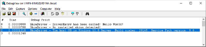
Now you should stop the driver and enable one of the shims present in the SDB database. In this example, you will start with one of the version lie shims. Stop the target driver and install the shim using the following commands (where ShimDriver64.sys is the driver’s file name installed with the previous step):
sc stop shimdriver
reg add "HKLMSystemCurrentControlSetControlCompatibilityDriver
    ShimDriver64.sys" /v Shims /t REG_MULTI_SZ /d
KmWin81VersionLie /f /reg:64
The last command adds the Windows 8.1 version lie shim, but you can freely choose other versions.
Now, if you restart the driver, you will see different messages printed by the DebugView tool, as shown in the following figure:
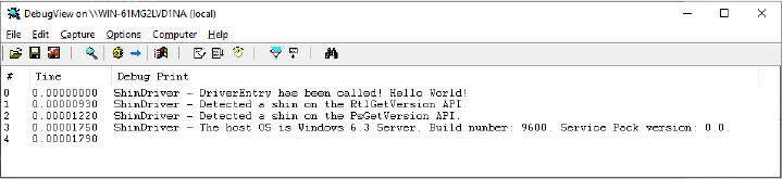
This is because the shim engine has correctly applied the hooks on the NT APIs used for retrieving OS version information (the driver is able to detect the shim, too). You should be able to repeat the experiment using other shims, like the SkipDriverUnload or the KernelPadSectionsOverride, which will zero out the driver unload routine or prevent the target driver from loading, as shown in the following figure:
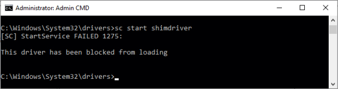
Device shims
Unlike Driver shims, shims applied to Device objects are loaded and applied on demand. The NT kernel exports the KseQueryDeviceData function, which allows drivers to check whether a shim needs to be applied to a device object. (Note also that the KseQueryDeviceFlags function is exported. The API is just a subset of the first one, though.) Querying for device shims is also possible for user-mode applications through the NtQuerySystemInformation API used with the SystemDeviceDataInformation information class. Device shims are always stored in three different locations, consulted in the following order:
In the HKLMSystemCurrentControlSetControlCompatibilityDevice root registry key, using a key named as the PNP hardware ID of the device, replacing the character with a ! (with the goal to not confuse the registry). Values in the device key specify the device’s shimmed data being queried (usually flags for a certain device class).
In the kernel shim cache. The Kernel Shim engine implements a shim cache (exposed through the KSE_CACHE data structure) with the goal of speeding up searches for device flags and data.
In the Shim database file, using the KDEVICE root tag. The root tag, among many others (like device description, manufacturer name, GUID and so on), includes the child NAME tag containing a string composed as follows: <DataName:HardwareID>. The KFLAG or KDATA children tags include the value for the device’s shimmed data.
If the device shim is not present in the cache but just in the SDB file, it is always added. In that way, future interrogation would be faster and will not require any access to the Shim database file.
Conclusion
In this chapter, we have described the most important features of the Windows operating system that provide management facilities, like the Windows Registry, user-mode services, task scheduling, UBPM, and Windows Management Instrumentation (WMI). Furthermore, we have discussed how Event Tracing for Windows (ETW), DTrace, Windows Error Reporting (WER), and Global Flags (GFlags) provide the services that allow users to better trace and diagnose issues arising from any component of the OS or user-mode applications. The chapter concluded with a peek at the Kernel Shim engine, which helps the system apply compatibility strategies and correctly execute old components that have been designed for older versions of the operating system.
The next chapter delves into the different file systems available in Windows and with the global caching available for speeding up file and data access.