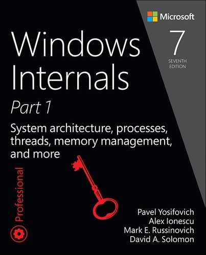
Working set management
Every process starts with a default working set minimum of 50 pages and a working set maximum of 345 pages. Although it has little effect, you can change these working set limits with the Windows SetProcessWorkingSetSize function, although you must have the increase scheduling priority (SeIncreaseBasePriorityPrivilege) privilege to do this. However, unless you have configured the process to use hard working set limits, these limits are ignored. That is, the memory manager will permit a process to grow beyond its maximum if it is paging heavily and there is ample memory. (Conversely the memory manager will shrink a process below its working set minimum if it is not paging and there is a high demand for physical memory on the system.) You can set hard working set limits using the SetProcessWorkingSetSizeEx function along with the QUOTA_LIMITS_HARDWS_MAX_ENABLE flag, but it is almost always better to let the system manage your working set.
On 32 bit systems, the maximum working set size can’t exceed the system-wide maximum calculated at system initialization time, stored in the MiMaximumWorkingSet kernel variable. On x64 systems, physical memory would be the practical upper limit, as the virtual address space is so vast. The working set maximums are listed in Table 5-15.

When a page fault occurs, the process’s working set limits and the amount of free memory on the system are examined. If conditions permit, the memory manager allows a process to grow to its working set maximum (or beyond if the process does not have a hard working set limit and there are enough free pages available). However, if memory is tight, Windows replaces rather than adds pages in a working set when a fault occurs.
Windows attempts to keep memory available by writing modified pages to disk. Still, when modified pages are being generated at a very high rate, more memory is required to meet memory demands. Therefore, when physical memory runs low, the working set manager, a routine that runs in the context of the balance set manager system thread (described in the next section), initiates automatic working set trimming to increase the amount of free memory available in the system. You can also initiate working set trimming of your own process—for example, after process initialization—with the aforementioned Windows SetProcessWorkingSetSizeEx function.
The working set manager examines available memory and decides which, if any, working sets need to be trimmed. If there is ample memory, the working set manager calculates how many pages could be removed from working sets if needed. If trimming is needed, it looks at working sets that are above their minimum setting. It also dynamically adjusts the rate at which it examines working sets and arranges the list of processes that are candidates to be trimmed into an optimal order. For example, processes with many pages that have not been accessed recently are examined first; larger processes that have been idle longer are considered before smaller processes that are running more often; the process running the foreground application is considered last; and so on.
When the working set manager finds processes that are using more than their minimums, it looks for pages to remove from the working sets, making the pages available for other uses. If the amount of free memory is still too low, the working set manager continues removing pages from processes’ working sets until it achieves a minimum number of free pages on the system.
The working set manager tries to remove pages that haven’t been accessed recently by checking the accessed bit in the hardware PTE to see whether a page has been accessed. If the bit is clear, the page is said to be aged. That is, a count is incremented indicating that the page hasn’t been referenced since the last working set trim scan. Later, the age of pages is used to locate candidate pages to remove from the working set.
If the hardware PTE accessed bit is set, the working set manager clears it and goes on to examine the next page in the working set. In this way, if the accessed bit is clear the next time the working set manager examines the page, it knows that the page hasn’t been accessed since the last time it was examined. This scan for pages to remove continues through the working set list until either the number of desired pages has been removed or the scan has returned to the starting point. The next time the working set is trimmed, the scan picks up where it left off last.
EXPERIMENT: Working set versus virtual size
1. Create a new TestLimit process.
C:Userspavely>testlimit -d 1 -c 800
Testlimit v5.24 - test Windows limits
Copyright (C) 2012-2015 Mark Russinovich
Sysinternals - www.sysinternals.com
Process ID: 13008
Leaking private bytes with touch 1 MB at a time...
Leaked 800 MB of private memory (800 MB total leaked). Lasterror: 0
The operation completed successfully.
2. Open Process Explorer.
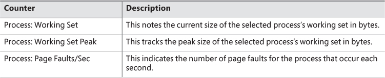
3. Open the View menu, choose Select Columns, and click the Process Memory tab.
4. Enable the Private Bytes, Virtual Size, Working Set Size, WS Shareable Bytes, and WS Private Bytes counters.
5. Find the three instances of TestLimit, as shown in the display:

Balance set manager and swapper
Working set expansion and trimming take place in the context of a system thread called the balance set manager (KeBalanceSetManager function). The balance set manager is created during system initialization. Although the balance set manager is technically part of the kernel, it calls the memory manager’s working set manager (MmWorkingSetManager) to perform working set analysis and adjustment.
The balance set manager waits for two different event objects: an event that is signaled when a periodic timer set to fire once per second expires and an internal working set manager event that the memory manager signals at various points when it determines that working sets need to be adjusted. For example, if the system is experiencing a high page fault rate or the free list is too small, the memory manager wakes up the balance set manager so that it will call the working set manager to begin trimming working sets. When memory is more plentiful, the working set manager permits faulting processes to gradually increase the size of their working sets by faulting pages back into memory. However, the working sets will grow only as needed.
When the balance set manager wakes up because its 1-second timer has expired, it takes the following steps:
1. If the system supports Virtual Secure Mode (VSM, Windows 10 and Server 2016), then the secure kernel is called to do its periodic housekeeping (VslSecureKernelPeriodicTick).
2. Calls a routine to adjust IRP credits to optimize the usage of the per-processor look-aside lists used in IRP completion (IoAdjustIrpCredits). This allows better scalability when certain processors are under heavy I/O load. (See Chapter 6 for more on IRPs.)
3. Checks the look-aside lists and adjusts their depths (if necessary) to improve access time and reduce pool usage and pool fragmentation (ExAdjustLookasideDepth).
4. Calls to adjust the Event Tracing for Windows (ETW) buffer pool size to use ETW memory buffers more efficiently (EtwAdjustTraceBuffers). (For more on ETW, see Chapter 8 in Part 2.)
5. Calls the memory manager’s working set manager. The working set manager has its own internal counters that regulate when to perform working set trimming and how aggressively to trim.
6. Enforces execution time for jobs (PsEnforceExecutionLimits).
7. Every eighth time the balance set manager wakes up because its 1-second timer has expired, it signals an event that wakes up another system thread called the swapper (KeSwapProcess-OrStack). It attempts to outswap kernel stacks for threads that have not executed for a long time. The swapper thread (which runs at priority 23) looks for threads that have been in a user mode wait state for 15 seconds. If it finds one, it puts the thread’s kernel stack in transition (moving the pages to the modified or standby lists) to reclaim its physical memory, operating on the principle that if a thread has been waiting that long, it’s going to be waiting even longer. When the last thread in a process has its kernel stack removed from memory, the process is marked to be entirely outswapped. That’s why, for example, processes that have been idle for a long time (such as Wininit or Winlogon) can have a working set size of zero.
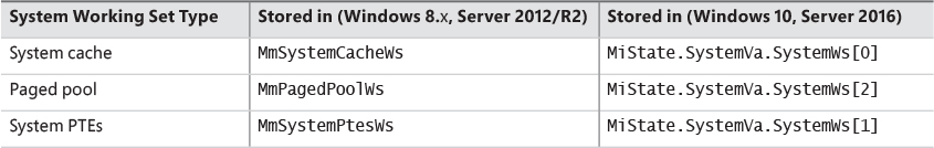
System working sets
Just as processes have working sets that manage pageable portions of the process address space, the pageable code and data in the system address space is managed using three global working sets, collectively known as the system working sets. These global working sets are as follows:
![]() System cache working set This contains pages that are resident in the system cache.
System cache working set This contains pages that are resident in the system cache.
![]() Paged pool working set This contains pages that are resident in the paged pool.
Paged pool working set This contains pages that are resident in the paged pool.
![]() System PTEs working set This contains pageable code and data from loaded drivers and the kernel image and pages from sections that have been mapped into the system space.
System PTEs working set This contains pageable code and data from loaded drivers and the kernel image and pages from sections that have been mapped into the system space.
Table 5-16 shows where these system working set types are stored.
You can examine the sizes of these working sets or the sizes of the components that contribute to them with the performance counters or system variables shown in Table 5-17. (Note that the performance counter values are in bytes, whereas the system variables are measured in pages.)
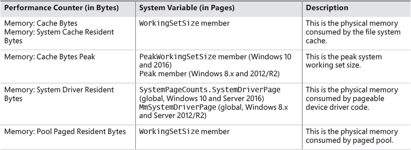
You can also examine the paging activity in the system cache working set by examining the Memory: Cache Faults/Sec performance counter. This counter describes page faults that occur in the system cache working set (both hard and soft). The PageFaultCount member in the system cache working set structure contains the value for this counter.
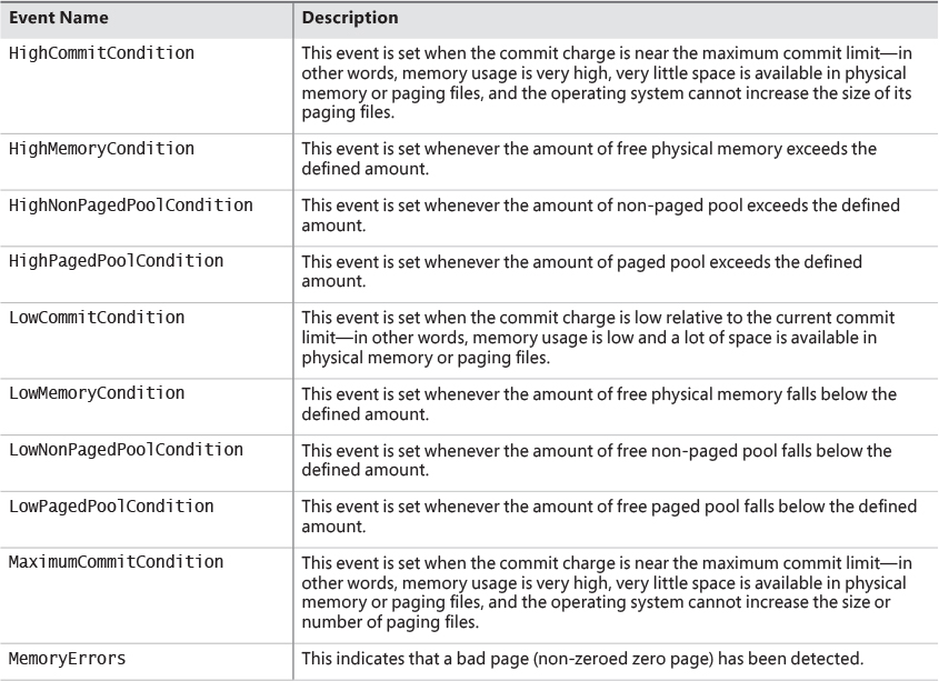
Memory notification events
Windows provides a way for user-mode processes and kernel-mode drivers to be notified when physical memory, paged pool, non-paged pool, and commit charge are low and/or plentiful. This information can be used to determine memory usage as appropriate. For example, if available memory is low, the application can reduce memory consumption. If available paged pool is high, the driver can allocate more memory. Finally, the memory manager also provides an event that permits notification when corrupted pages have been detected.
User-mode processes can be notified only of low or high memory conditions. An application can call the CreateMemoryResourceNotification function, specifying whether low or high memory notification is desired. The returned handle can be provided to any of the wait functions. When memory is low (or high), the wait completes, thus notifying the thread of the condition. Alternatively, the QueryMemory-ResourceNotification can be used to query the system memory condition at any time without blocking the calling thread.
Drivers, on the other hand, use the specific event name that the memory manager has set up in the KernelObjects object manager directory. This is because notification is implemented by the memory manager signaling one of the globally named event objects it defines, shown in Table 5-18. When a given memory condition is detected, the appropriate event is signaled, thus waking up any waiting threads.
![]() Note
Note
You can override the high and low memory values by adding the LowMemoryThreshold or HighMemoryThreshold DWORD registry value under HKLMSYSTEMCurrentControlSetControlSession ManagerMemory Management. This specifies the number of megabytes to use as the low or high threshold. You can also configure the system to crash when a bad page is detected instead of signaling a memory error event by setting the PageValidationAction DWORD registry value in the same key to 1.
Page frame number database
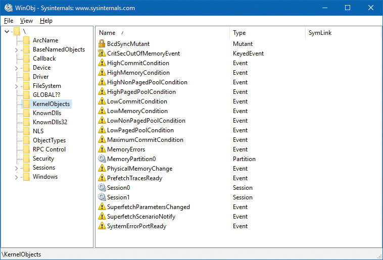
Several previous sections concentrated on the virtual view of a Windows process—page tables, PTEs, and VADs. The remainder of this chapter will explain how Windows manages physical memory, starting with how Windows keeps track of physical memory. Whereas working sets describe the resident pages owned by a process or the system, the PFN database describes the state of each page in physical memory. The page states are listed in Table 5-19.
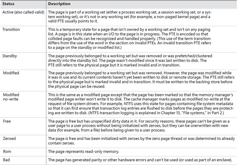
The PFN database consists of an array of structures that represent each physical page of memory on the system. The PFN database and its relationship to page tables are shown in Figure 5-35. As this figure shows, valid PTEs usually point to entries in the PFN database (and the PFN index points to the page in physical memory), and the PFN database entries (for non-prototype PFNs) point back to the page table that is using them (if it is being used by a page table). For prototype PFNs, they point back to the prototype PTE.
Of the page states listed in Table 5-19, six are organized into linked lists so that the memory manager can quickly locate pages of a specific type. (Active/valid pages, transition pages, and overloaded “bad” pages aren’t in any system-wide page list.) Additionally, the standby state is associated with eight different lists ordered by priority. (We’ll talk about page priority later in this section.) Figure 5-36 shows an example of how these entries are linked together.

In the next section, you’ll find out how these linked lists are used to satisfy page faults and how pages move to and from the various lists.
Page list dynamics
Figure 5-37 shows a state diagram for page frame transitions. For simplicity, the modified-no-write, bad and ROM lists aren’t shown.
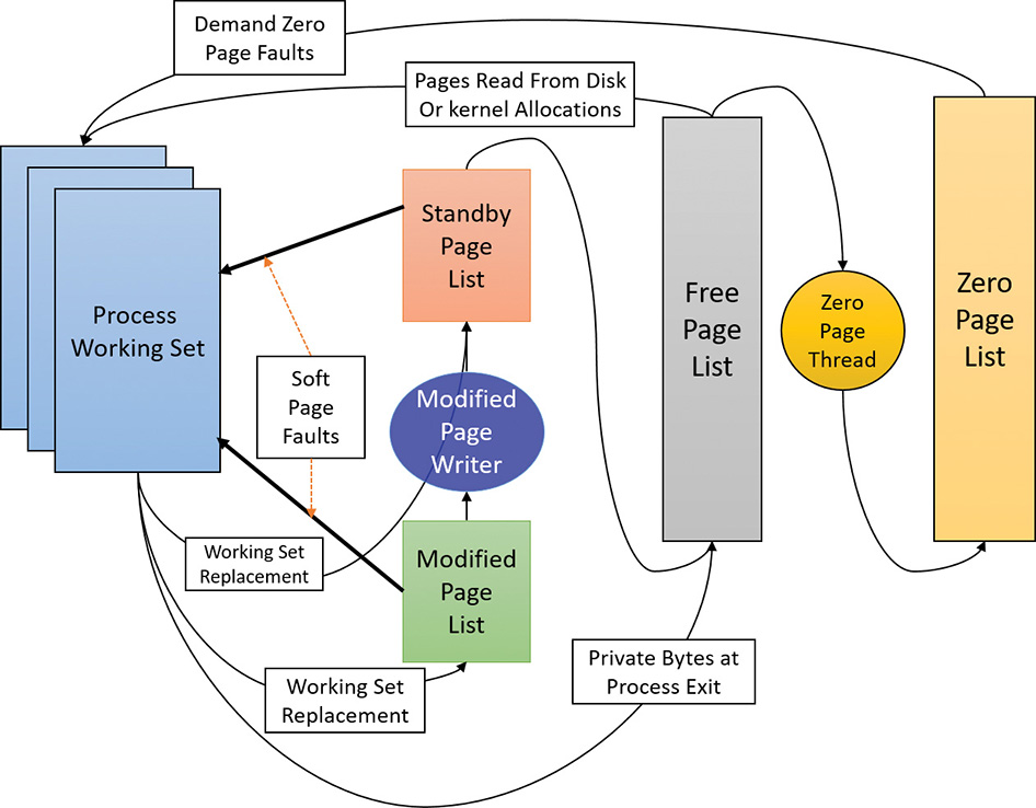
Page frames move between the paging lists in the following ways:
![]() When the memory manager needs a zero-initialized page to service a demand-zero page fault (a reference to a page that is defined to be all zeroes or to a user-mode committed private page that has never been accessed), it first attempts to get one from the zero page list. If the list is empty, it gets one from the free page list and zeroes the page. If the free list is empty, it goes to the standby list and zeroes that page.
When the memory manager needs a zero-initialized page to service a demand-zero page fault (a reference to a page that is defined to be all zeroes or to a user-mode committed private page that has never been accessed), it first attempts to get one from the zero page list. If the list is empty, it gets one from the free page list and zeroes the page. If the free list is empty, it goes to the standby list and zeroes that page.
One reason zero-initialized pages are needed is to meet security requirements such as the Common Criteria (CC). Most CC profiles specify that user-mode processes be given initialized page frames to prevent them from reading a previous process’s memory contents. Thus, the memory manager gives user-mode processes zeroed page frames unless the page is being read in from a backing store. In that case, the memory manager prefers to use non-zeroed page frames, initializing them with the data off the disk or remote storage. The zero page list is populated from the free list by the zero page thread system thread (thread 0 in the System process). The zero page thread waits on a gate object to signal it to go to work. When the free list has eight or more pages, this gate is signaled. However, the zero page thread will run only if at least one processor has no other threads running, because the zero page thread runs at priority 0 and the lowest priority that a user thread can be set to is 1.
![]() Note
Note
When memory needs to be zeroed as a result of a physical page allocation by a driver that calls MmAllocatePagesForMdl(Ex), by a Windows application that calls AllocateUserPhysicalPages or AllocateUserPhysicalPagesNuma, or when an application allocates large pages, the memory manager zeroes the memory by using a higher-performing function called MiZeroInParallel that maps larger regions than the zero page thread, which only zeroes a page at a time. In addition, on multiprocessor systems, the memory manager creates additional system threads to perform the zeroing in parallel (and in a NUMA-optimized fashion on NUMA platforms).
![]() When the memory manager doesn’t require a zero-initialized page, it goes first to the free list. If that’s empty, it goes to the zeroed list. If the zeroed list is empty, it goes to the standby lists. Before the memory manager can use a page frame from the standby lists, it must first backtrack and remove the reference from the invalid PTE (or prototype PTE) that still points to the page frame. Because entries in the PFN database contain pointers back to the previous user’s page table page (or to a page of prototype PTE pool for shared pages), the memory manager can quickly find the PTE and make the appropriate change.
When the memory manager doesn’t require a zero-initialized page, it goes first to the free list. If that’s empty, it goes to the zeroed list. If the zeroed list is empty, it goes to the standby lists. Before the memory manager can use a page frame from the standby lists, it must first backtrack and remove the reference from the invalid PTE (or prototype PTE) that still points to the page frame. Because entries in the PFN database contain pointers back to the previous user’s page table page (or to a page of prototype PTE pool for shared pages), the memory manager can quickly find the PTE and make the appropriate change.
![]() When a process must give up a page out of its working set either because it referenced a new page and its working set was full or the memory manager trimmed its working set, the page goes to the standby lists if the page was clean (not modified) or to the modified list if the page was modified while it was resident.
When a process must give up a page out of its working set either because it referenced a new page and its working set was full or the memory manager trimmed its working set, the page goes to the standby lists if the page was clean (not modified) or to the modified list if the page was modified while it was resident.
![]() When a process exits, all the private pages go to the free list. Also, when the last reference to a page-file-backed section is closed, and the section has no remaining mapped views, these pages also go to the free list.
When a process exits, all the private pages go to the free list. Also, when the last reference to a page-file-backed section is closed, and the section has no remaining mapped views, these pages also go to the free list.
EXPERIMENT: The modified and standby page lists
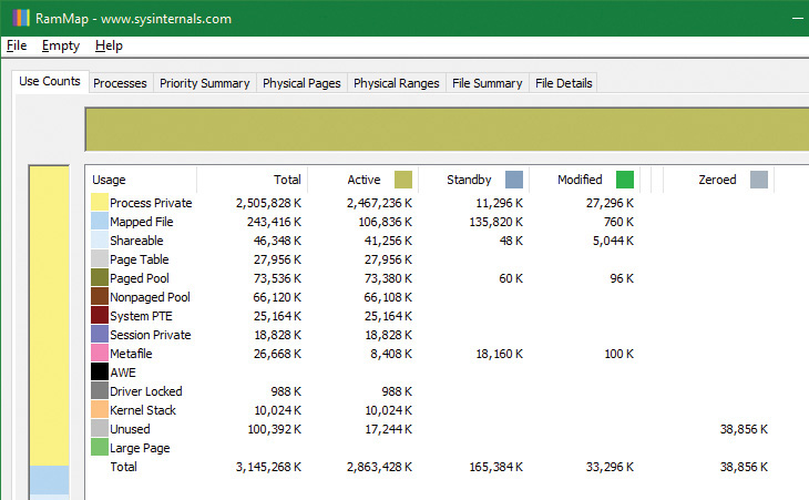
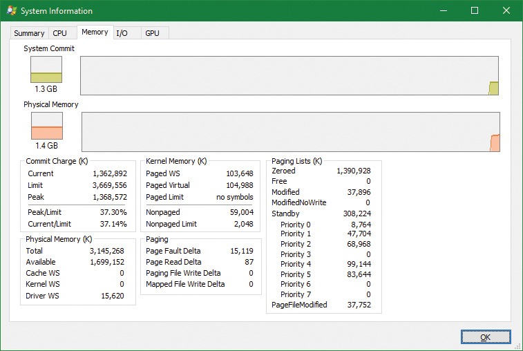
1. Open RAMMap and observe the state of the quiet system. This is an x86 system with 3 GB of RAM. The columns in this display represent the various page states shown in Figure 5-37 (a few of the columns not important to this discussion have been narrowed for ease of reference).

2. The system has about 420 MB of RAM free (sum of the free and zeroed page lists). About 580 MB is on the standby list (hence part of “available,” but likely containing data recently lost from processes or being used by SuperFetch). About 830 MB is “active,” being mapped directly to virtual addresses via valid page table entries.
3. Each row further breaks down into page state by usage or origin (process private, mapped file, and so on). For example, at the moment, of the active 830 MB, about 400 MB is due to process private allocations.
4. Now, as in the previous experiment, use the TestLimit utility to create a process with a large number of pages in its working set. Again, we will use the –d option to cause TestLimit to write to each page, but this time we will use it without a limit, so as to create as many private modified pages as possible:
C:ToolsSysinternals>Testlimit.exe -d
Testlimit v5.24 - test Windows limits
Copyright (C) 2012-2015 Mark Russinovich
Sysinternals - www.sysinternals.com
Process ID: 7548
Leaking private bytes with touch (MB)...
Leaked 1975 MB of private memory (1975 MB total leaked). Lasterror: 8
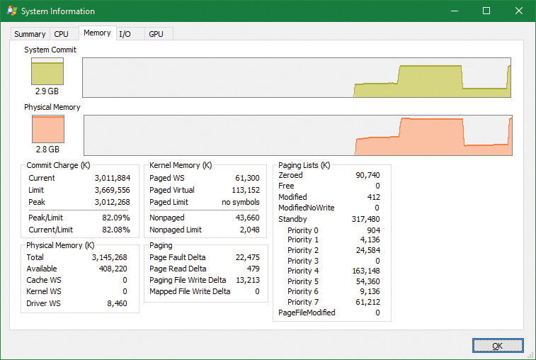
5. TestLimit has now created 1975 allocations of 1 MB each. In RAMMap, use the File | Refresh command to update the display (because of the cost of gathering its information, RAMMap does not update continuously).
6. You will see that over 2.8 GB are now active, of which 2.4 GB are in the Process Private row. This is due to the memory allocated and accessed by the TestLimit process. Note also that the standby, zeroed, and free lists are now much smaller. Most of the RAM allocated to TestLimit came from these lists.
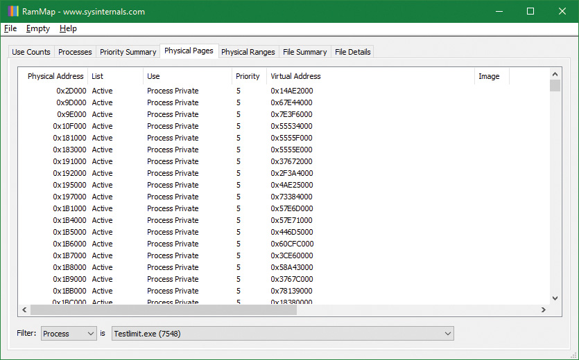
7. Next, in RAMMap, check the process’s physical page allocations. Change to the Physical Pages tab, and set the filter at the bottom to the Process column and the value Testlimit.exe. This display shows all the physical pages that are part of the process working set.
8. We would like to identify a physical page involved in the allocation of virtual address space done by TestLimit’s –d option. RAMMap does not give an indication about which virtual allocations are associated with RAMMap’s VirtualAlloc calls. However, we can get a good hint of this through the VMMap tool. Using VMMap on the same process, we find the following:
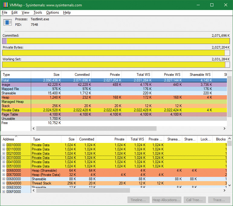
9. In the lower part of the display, we find hundreds of allocations of process private data, each 1 MB in size and with 1 MB committed. These match the size of the allocations done by TestLimit. One of these is highlighted in the preceding screenshot. Note the starting virtual address, 0x310000.
10. Now go back to RAMMap’s physical memory display. Arrange the columns to make the Virtual Address column easily visible, click it to sort by that value, and you can find that virtual address:

11. This shows that the virtual page starting at 0x310000 is currently mapped to physical address 0x212D1000. TestLimit’s –d option writes the program’s own name to the first bytes of each allocation. We can demonstrate this with the !dc (display characters using physical address) command in the local kernel debugger:
lkd> !dc 0x212d1000
#212d1000 74736554 696d694c 00000074 00000000 TestLimit.......
#212d1010 00000000 00000000 00000000 00000000 ................
...
12. If you’re not quick enough, this may fail—the page may be removed from the working set. For the final leg of the experiment, we will demonstrate that this data remains intact (for a while, anyway) after the process working set is reduced and this page is moved to the modified and then the standby page list.
13. In VMMap, having selected the TestLimit process, open the View menu and choose Empty Working Set to reduce the process’s working set to the bare minimum. VMMap’s display should now look like this:

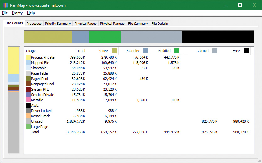
14. Notice that the Working Set bar graph is practically empty. In the middle section, the process shows a total working set of only 4 KB, and almost all of it is in page tables. Now return to RAMMap and refresh it. On the Use Counts tab, you will find that active pages have been reduced tremendously, with a large number of pages on the modified list and some on the standby list:
15. RAMMap’s Processes tab confirms that the TestLimit process contributed most of those pages to those lists:

Page priority
Every physical page in the system has a page priority value assigned to it by the memory manager. The page priority is a number in the range 0 to 7. Its main purpose is to determine the order in which pages are consumed from the standby list. The memory manager divides the standby list into eight sublists that each stores pages of a particular priority. When the memory manager wants to take a page from the standby list, it takes pages from low-priority lists first.
Each thread and process in the system is also assigned a page priority. A page’s priority usually reflects the page priority of the thread that first causes its allocation. (If the page is shared, it reflects the highest page priority among the sharing threads.) A thread inherits its page-priority value from the process to which it belongs. The memory manager uses low priorities for pages it reads from disk speculatively when anticipating a process’s memory accesses.
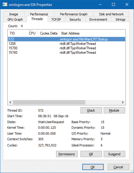
By default, processes have a page-priority value of 5, but the SetProcessInformation and SetThreadInformation user-mode functions allow applications to change process and thread page-priority values. These functions call the native NtSetInformationProcess and NtSetInformationThread functions. You can look at the memory priority of a thread with Process Explorer (per-page priority can be displayed by looking at the PFN entries, as you’ll see in an experiment later in the chapter). Figure 5-38 shows Process Explorer’s Threads tab displaying information about Winlogon’s main thread. Although the thread priority itself is high, the memory priority is still the standard 5.
The real power of memory priorities is realized only when the relative priorities of pages are understood at a high level, which is the role of SuperFetch, covered at the end of this chapter.
Modified page writer and mapped page writer
The memory manager employs two system threads to write pages back to disk and move those pages back to the standby lists (based on their priority). One system thread writes out modified pages (MiModifiedPageWriter) to the paging file, and a second one writes modified pages to mapped files (MiMappedPageWriter). Two threads are required to avoid creating a deadlock. This would occur if the writing of mapped file pages caused a page fault that in turn required a free page when no free pages were available, thus requiring the modified page writer to create more free pages. By having the modified page writer perform mapped file paging I/Os from a second system thread, that thread can wait without blocking regular page file I/O.
Both threads run at priority 18, and after initialization they wait for separate event objects to trigger their operation. The mapped page writer waits on 18 event objects:
![]() An exit event, signaling the thread to exit (not relevant to this discussion).
An exit event, signaling the thread to exit (not relevant to this discussion).
![]() The mapped writer event, stored in the global variable
The mapped writer event, stored in the global variable MiSystemPartition.Modwriter.MappedPageWriterEvent (MmMappedPageWriterEvent on Windows 8.x and Server 2012/R2). This event can be signaled in the following instances:
• During a page list operation (MiInsertPageInList); this routine inserts a page into one of the lists (standby, modified, etc.) based on its input arguments. The routine signals this event if the number of file-system-destined pages on the modified page list has reached more than 16 and the number of available pages has fallen below 1024.
• In an attempt to obtain free pages (MiObtainFreePages).
• By the memory manager’s working set manager (MmWorkingSetManager), which runs as part of the kernel’s balance set manager (once every second). The working set manager signals this event if the number of file-system-destined pages on the modified page list has reached more than 800.
• Upon a request to flush all modified pages (MmFlushAllPages).
• Upon a request to flush all file-system-destined modified pages (MmFlushAllFilesystemPages). Note that in most cases, writing modified mapped pages to their backing store files does not occur if the number of mapped pages on the modified page list is less than the maximum write cluster size, which is 16 pages. This check is not made in MmFlushAllFilesystemPages or MmFlushAllPages.
![]() An array of 16 events associated with 16 mapped page lists, stored in
An array of 16 events associated with 16 mapped page lists, stored in MiSystemPartition.PageLists.MappedPageListHeadEvent (MiMappedPageListHeadEvent on Windows 8.x and Server 2012/R2). Each time a mapped page is dirtied, it is inserted into one of these 16 mapped page lists based on a bucket number, stored in MiSystemPartition.WorkingSetControl->CurrentMappedPageBucket (MiCurrentMappedPageBucket on Windows 8.x and Server 2012/R2). This bucket number is updated by the working set manager whenever the system considers that mapped pages have gotten old enough, which is currently 100 seconds (stored in the WriteGapCounter variable in the same structure [MiWriteGapCounter on Windows 8.x and Server 2012/R2] and incremented whenever the working set manager runs). The reason for these additional events is to reduce data loss in the case of a system crash or power failure by eventually writing out modified mapped pages even if the modified list hasn’t reached its threshold of 800 pages.
The modified page writer waits on two events: the first is an Exit event, and the second stored in MiSystemPartition.Modwriter.ModifiedPageWriterEvent (on Windows 8.x and Server 2012/R2 waits on a kernel gate stored in MmModifiedPageWriterGate), which can be signaled in the following scenarios:
![]() A request to flush all pages has been received.
A request to flush all pages has been received.
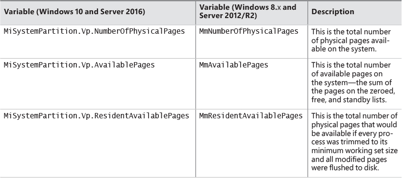
![]() The number of available pages—stored in
The number of available pages—stored in MiSystemPartition.Vp.AvailablePages (MmAvailablePages on Windows 8.x and Server 2012/R2)—drops below 128 pages.
![]() The total size of the zeroed and free page lists drops below 20,000 pages, and the number of modified pages destined for the paging file is greater than the smaller of one-sixteenth of the available pages or 64 MB (16,384 pages).
The total size of the zeroed and free page lists drops below 20,000 pages, and the number of modified pages destined for the paging file is greater than the smaller of one-sixteenth of the available pages or 64 MB (16,384 pages).
![]() When a working set is being trimmed to accommodate additional pages, if the number of pages available is less than 15,000.
When a working set is being trimmed to accommodate additional pages, if the number of pages available is less than 15,000.
![]() During a page list operation (
During a page list operation (MiInsertPageInList). This routine signals this event if the number of page-file-destined pages on the modified page list has reached more than 16 pages and the number of available pages has fallen below 1,024.
Additionally, the modified page writer waits on two other events after the preceding event is signaled. One is used to indicate rescanning of the paging file is required (for example, a new page file may have been created), stored in MiSystemPartition.Modwriter.RescanPageFilesEvent (MiRescanPageFilesEvent on Windows 8.x and Server 2012/R2). The second event is internal to the paging file header (MiSystemPartition.Modwriter.PagingFileHeader [MmPagingFileHeader on Windows 8.x and Server 2012/R2]), which allows the system to manually request flushing out data to the paging file when needed.
When invoked, the mapped page writer attempts to write as many pages as possible to disk with a single I/O request. It accomplishes this by examining the original PTE field of the PFN database elements for pages on the modified page list to locate pages in contiguous locations on the disk. Once a list is created, the pages are removed from the modified list, an I/O request is issued, and, at successful completion of the I/O request, the pages are placed at the tail of the standby list corresponding to their priority.
Pages that are in the process of being written can be referenced by another thread. When this happens, the reference count and the share count in the PFN entry that represents the physical page are incremented to indicate that another process is using the page. When the I/O operation completes, the modified page writer notices that the reference count is no longer 0 and doesn’t place the page on any standby list.
PFN data structures
Although PFN database entries are of fixed length, they can be in several different states, depending on the state of the page. Thus, individual fields have different meanings depending on the state. Figure 5-39 shows the formats of PFN entries for different states.

Several fields are the same for several PFN types, but others are specific to a given type of PFN. The following fields appear in more than one PFN type:
![]() PTE address This is the virtual address of the PTE that points to this page. Also, since PTE addresses will always be aligned on a 4-byte boundary (8 bytes on 64-bit systems), the two low-order bits are used as a locking mechanism to serialize access to the PFN entry.
PTE address This is the virtual address of the PTE that points to this page. Also, since PTE addresses will always be aligned on a 4-byte boundary (8 bytes on 64-bit systems), the two low-order bits are used as a locking mechanism to serialize access to the PFN entry.
![]() Reference count This is the number of references to this page. The reference count is incremented when a page is first added to a working set and/or when the page is locked in memory for I/O (for example, by a device driver). The reference count is decremented when the share count becomes 0 or when pages are unlocked from memory. When the share count becomes 0, the page is no longer owned by a working set. Then, if the reference count is also zero, the PFN database entry that describes the page is updated to add the page to the free, standby, or modified list.
Reference count This is the number of references to this page. The reference count is incremented when a page is first added to a working set and/or when the page is locked in memory for I/O (for example, by a device driver). The reference count is decremented when the share count becomes 0 or when pages are unlocked from memory. When the share count becomes 0, the page is no longer owned by a working set. Then, if the reference count is also zero, the PFN database entry that describes the page is updated to add the page to the free, standby, or modified list.
![]() Type This is the type of page represented by this PFN. (Types include active/valid, standby, modified, modified-no-write, free, zeroed, bad, and transition.)
Type This is the type of page represented by this PFN. (Types include active/valid, standby, modified, modified-no-write, free, zeroed, bad, and transition.)
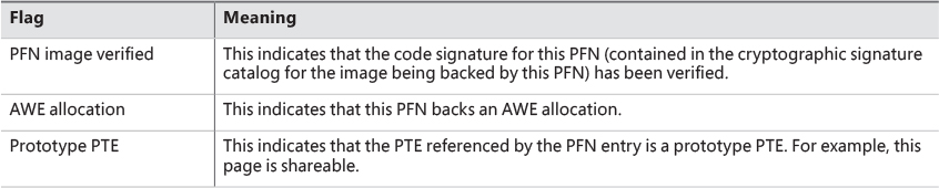
![]() Flags The information contained in the flags field is shown in Table 5-20.
Flags The information contained in the flags field is shown in Table 5-20.
![]() Priority This is the priority associated with this PFN, which will determine on which standby list it will be placed.
Priority This is the priority associated with this PFN, which will determine on which standby list it will be placed.
![]() Original PTE contents All PFN database entries contain the original contents of the PTE that pointed to the page (which could be a prototype PTE). Saving the contents of the PTE allows it to be restored when the physical page is no longer resident. PFN entries for AWE allocations are exceptions; they store the AWE reference count in this field instead.
Original PTE contents All PFN database entries contain the original contents of the PTE that pointed to the page (which could be a prototype PTE). Saving the contents of the PTE allows it to be restored when the physical page is no longer resident. PFN entries for AWE allocations are exceptions; they store the AWE reference count in this field instead.
![]() PFN of PTE This is the physical page number of the page table page containing the PTE that points to this page.
PFN of PTE This is the physical page number of the page table page containing the PTE that points to this page.
![]() Color Besides being linked together on a list, PFN database entries use an additional field to link physical pages by “color,” which is the page’s NUMA node number.
Color Besides being linked together on a list, PFN database entries use an additional field to link physical pages by “color,” which is the page’s NUMA node number.
![]() Flags A second flags field is used to encode additional information on the PTE. These flags are described in Table 5-21.
Flags A second flags field is used to encode additional information on the PTE. These flags are described in Table 5-21.

The remaining fields are specific to the type of PFN. For example, the first PFN in Figure 5-39 represents a page that is active and part of a working set. The share count field represents the number of PTEs that refer to this page. (Pages marked read-only, copy-on-write, or shared read/write can be shared by multiple processes.) For page table pages, this field is the number of valid and transition PTEs in the page table. As long as the share count is greater than 0, the page isn’t eligible for removal from memory.
The working set index field is an index into the process working set list (or the system or session working set list, or zero if not in any working set) where the virtual address that maps this physical page resides. If the page is a private page, the working set index field refers directly to the entry in the working set list because the page is mapped only at a single virtual address. In the case of a shared page, the working set index is a hint that is guaranteed to be correct only for the first process that made the page valid. (Other processes will try to use the same index where possible.) The process that initially sets this field is guaranteed to refer to the proper index and doesn’t need to add a working set list hash entry referenced by the virtual address into its working set hash tree. This guarantee reduces the size of the working set hash tree and makes searches faster for these entries.
The second PFN in Figure 5-39 is for a page on either the standby or the modified list. In this case, the forward and backward link fields link the elements of the list together within the list. This linking allows pages to be easily manipulated to satisfy page faults. When a page is on one of the lists, the share count is by definition 0 (because no working set is using the page) and therefore can be overlaid with the backward link. The reference count is also 0 if the page is on one of the lists. If it is non-zero (because an I/O could be in progress for this page—for example, when the page is being written to disk), it is first removed from the list.
The third PFN in Figure 5-39 is for a page that belongs to a kernel stack. As mentioned earlier, kernel stacks in Windows are dynamically allocated, expanded, and freed whenever a callback to user mode is performed and/or returns, or when a driver performs a callback and requests stack expansion. For these PFNs, the memory manager must keep track of the thread actually associated with the kernel stack, or if it is free it keeps a link to the next free look-aside stack.
The fourth PFN in Figure 5-39 is for a page that has an I/O in progress (for example, a page read). While the I/O is in progress, the first field points to an event object that will be signaled when the I/O completes. If an in-page error occurs, this field contains the Windows error status code representing the I/O error. This PFN type is used to resolve collided page faults.
In addition to the PFN database, the system variables in Table 5-22 describe the overall state of physical memory.
Page file reservation
We have already seen some mechanisms used by the memory manager to attempt to reduce physical memory consumption and thus reduce accessing page files. Using the standby and modified list is one such mechanism, and so is memory compression (see the “Memory compression” section later in this chapter). Another optimization the memory uses is directly related to accessing page files themselves.
Rotational hard disks have a moving head that travels to a target sector before the disk can actually read or write. This seek time is relatively expensive (in the order of milliseconds) and so the total disk activity is the seek time added to the actual read/write time. If the amount of data accessed contiguously from the seek position is large, then the seek time may be negligible. But if the head must seek a lot while accessing scattered data on the disk, the aggregated seek time becomes the main issue.
When the Session Manager (Smss.exe) creates a page file, it queries the disk of the file’s partition to find whether it’s a rotational disk or a solid-state drive (SSD). If it’s rotational, it activates a mechanism called page file reservations that tries to keep contiguous pages in physical memory contiguous in the page file as well. If the disk is an SSD (or a hybrid, which for the sake of page file reservation is treated as SSD), then page file reservation adds no real value (since there is no moving head), and the feature is not utilized for this particular page file.
Page file reservation is handled in three locations within the memory manager: working set manager, modified page writer, and page fault handler. The working set manager performs working set trimming by calling the MiFreeWsleList routine. The routine takes a list of pages from a working set and for each page it decrements its share count. If it reaches zero, the page can be placed on the modified list, changing the relevant PTE into a transition PTE. The old valid PTE is saved in the PFN.
The invalid PTE has two bits related to page file reservation: page file reserved and page file allocated (refer to Figure 5-24). When a physical page is needed and is taken from one of the “free” page lists (free, zero or standby) to become an active (valid) page, an invalid PTE is saved into the Original PTE field of the PFN. This field is the key for tracking page file reservation.
The MiCheckReservePageFileSpace routine tries to create page file reservation cluster starting from a specified page. It checks if page file reservation is disabled for the target page file and if there is already page file reservation for this page (based on the original PTE), and if any of these conditions is true, the function aborts further processing for this page. The routine also checks if the page type is of user pages, and if not, it bails out. Page file reservation is not attempted for other page types (such as paged pool), because it was not found to be particularly beneficial (because of unpredictable usage patterns, for example), which led to small clusters. Finally, MiCheckReservePageFileSpace calls MiReservePageFileSpace to do the actual work.
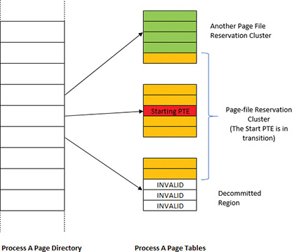
The search for page file reservation starts backward from the initial PTE. The goal is to locate eligible consecutive pages where reservation is possible. If the PTE that maps the neighboring page represents a decommitted page, a non-paged pool page, or if it’s already reserved, then the page cannot be used; the current page will become the lower limit of the reservation cluster. Otherwise, the search continues backward. Then the search starts from the initial page forward, trying to gather as many eligible pages as possible. The cluster size must be at least 16 pages for the reservation to take place (the maximum cluster size is 512 pages). Figure 5-40 shows an example of a cluster bound by invalid page on one hand and an existing cluster on the other (note that it can span page tables within the same page directory).
Once the page cluster is computed, free page file space must be located to be reserved for this cluster of pages. Page file allocations are managed by a bitmap (where each set bit indicates a used page in the file). For page file reservation, a second bitmap is used that indicates pages that have been reserved (but not necessarily written to yet—this is the job of the page file allocation bitmap). Once there is page file space that is not reserved and not allocated (based on these bitmaps), the relevant bits are set in the reservation bitmap only. It is the job of the modified page writer to set these bits in the allocation bitmap when it writes the contents of the pages to disk. If not enough page file space could be found for the required cluster size, page file expansion is attempted, and if that already happened (or the maximum page file size is the expanded size), then the cluster size is reduced to fit in the reservation size that was located.
![]() Note
Note
The clustered pages (except the original starting PTE) are not linked to any of the physical page lists. The reservation information is placed in the Original PTE of the PFN.
The modified page writer needs to handle writing pages that have reservations as a special case. It uses all the gathered information described previously to build an MDL that contains the correct PFNs for the cluster that is used as part of writing to the page file. Building the cluster includes finding contiguous pages that can span reservation clusters. If there are “holes” between clusters, a dummy page is added in between (a page that contains all bytes with 0xFF value). If the dummy page count is above 32, the cluster is broken. This “walk” is done going forward and then backward to build the final cluster to write. Figure 5-41 shows an example of the state of pages after such a cluster has been built by the modified page writer.

Finally, the page fault handler uses the built information from the reservation bitmap and the PTEs to determine the start and end points of clusters, to efficiently load back needed pages with minimal seeking of the mechanical disk head.
Physical memory limits
Now that you’ve learned how Windows keeps track of physical memory, we’ll describe how much of it Windows can actually support. Because most systems access more code and data than can fit in physical memory as they run, physical memory is essentially a window into the code and data used over time. The amount of memory can therefore affect performance because when data or code that a process or the operating system needs is not present, the memory manager must bring it in from disk or remote storage.
Besides affecting performance, the amount of physical memory affects other resource limits. For example, the amount of non-paged pool is backed by physical memory, thus obviously constrained by physical memory. Physical memory also contributes to the system virtual memory limit, which is the sum of roughly the size of physical memory plus the current configured size of all paging files. Physical memory also can indirectly limit the maximum number of processes.
Windows support for physical memory is dictated by hardware limitations, licensing, operating system data structures, and driver compatibility. The following URL shows the memory limits of the various Windows editions: https://msdn.microsoft.com/en-us/library/windows/desktop/aa366778.aspx. Table 5-23 summarizes the limits in Windows 8 and higher versions.

At the time of this writing, the maximum supported physical memory is 4 TB on some Server 2012/R2 editions and 24 TB on Server 2016 editions. The limitations don’t come from any implementation or hardware limitation, but because Microsoft will support only configurations it can test. As of this writing, these were the largest tested and supported memory configurations.
Windows client memory limits
64-bit Windows client editions support different amounts of memory as a differentiating feature, with the low end being 4 GB increasing to 2 TB for Enterprise and Professional editions. All 32-bit Windows client editions, however, support a maximum of 4 GB of physical memory, which is the highest physical address accessible with the standard x86 memory management mode.
Although client SKUs support PAE addressing modes on x86 systems in order to provide hardware no-execute protection (which would also enable access to more than 4 GB of physical memory), testing revealed that systems would crash, hang, or become unbootable because some device drivers, commonly those for video and audio devices found typically on clients but not servers, were not programmed to expect physical addresses larger than 4 GB. As a result, the drivers truncated such addresses, resulting in memory corruptions and corruption side effects. Server systems commonly have more generic devices, with simpler and more stable drivers, and therefore had not generally revealed these problems. The problematic client driver ecosystem led to the decision for client editions to ignore physical memory that resides above 4 GB, even though they can theoretically address it. Driver developers are encouraged to test their systems with the nolowmem BCD option, which will force the kernel to use physical addresses above 4 GB only if sufficient memory exists on the system to allow it. This will immediately lead to the detection of such issues in faulty drivers.
Although 4 GB is the licensed limit for 32-bit client editions, the effective limit is actually lower and depends on the system’s chipset and connected devices. This is because the physical address map includes not only RAM but device memory, and x86 and x64 systems typically map all device memory below the 4 GB address boundary to remain compatible with 32-bit operating systems that don’t know how to handle addresses larger than 4 GB. Newer chipsets do support PAE-based device remapping, but client editions of Windows do not support this feature for the driver compatibility problems explained earlier. (Otherwise, drivers would receive 64-bit pointers to their device memory.)
If a system has 4 GB of RAM and devices such as video, audio, and network adapters that implement windows into their device memory that sum to 500 MB, then 500 MB of the 4 GB of RAM will reside above the 4 GB address boundary, as shown in Figure 5-42.
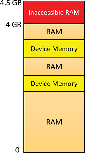
The result is that if you have a system with 3 GB or more of memory and you are running a 32-bit Windows client, you may not get the benefit of all the RAM. You can see how much RAM Windows has detected as being installed in the System Properties dialog box, but to see how much memory is really available to Windows, you need to look at Task Manager’s Performance page or the Msinfo32 utility. For example, on a Hyper-V virtual machine configured with 4 GB of RAM, with 32-bit Windows 10 installed, the amount of physical memory available is 3.87 GB, as shown in the Msinfo32 utility:
Installed Physical Memory (RAM) 4.00 GB
Total Physical Memory 3.87 GB
You can see the physical memory layout with the MemInfo tool. The following output is from MemInfo when run on a 32-bit system, using the –r switch to dump physical memory ranges:
C:Tools>MemInfo.exe -r
MemInfo v3.00 - Show PFN database information
Copyright (C) 2007-2016 Alex Ionescu
www.alex-ionescu.com
Physical Memory Range: 00001000 to 0009F000 (158 pages, 632 KB)
Physical Memory Range: 00100000 to 00102000 (2 pages, 8 KB)
Physical Memory Range: 00103000 to F7FF0000 (1015533 pages, 4062132 KB)
MmHighestPhysicalPage: 1015792
Note the gap in the memory address range from A0000 to 100000 (384 KB), and another gap from F8000000 to FFFFFFFF (128 MB).
You can use Device Manager on your machine to see what is occupying the various reserved memory regions that can’t be used by Windows (and that will show up as holes in MemInfo’s output). To check Device Manager, follow these steps:
1. Run Devmgmt.msc.
2. Open the View menu and select Resources by Connection.
3. Expand the Memory node. On the laptop computer used for the output shown in Figure 5-43, the primary consumer of mapped device memory is, unsurprisingly, the video card (Hyper-V S3 Cap), which consumes 128 MB in the range F8000000–FBFFFFFF.

Other miscellaneous devices account for most of the rest, and the PCI bus reserves additional ranges for devices as part of the conservative estimation the firmware uses during boot.
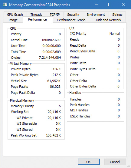
Memory compression
The Windows 10 memory manager implements a mechanism that compresses private and page-file-backed section pages that are on the modified page list. The primary candidates for compression are private pages belonging to UWP apps because compression works very well with the working set swapping and emptying that already occurs for such applications if memory is tight. After an application is suspended and its working set is outswapped, the working set can be emptied at any time and dirty pages can be compressed. This will create additional available memory that may be enough to hold another application in memory without making the first application’s pages leave memory.
![]() Note
Note
Experiments have shown that pages compress to around 30–50 percent of their original size using Microsoft’s Xpress algorithm, which balances speed with size, thus resulting in considerable memory savings.
The memory compression architecture must adhere to the following requirements:
![]() A page cannot be in memory in a compressed and an uncompressed form because this would waste physical memory due to duplication. This means that whenever a page is compressed, it must become a free page after successful compression.
A page cannot be in memory in a compressed and an uncompressed form because this would waste physical memory due to duplication. This means that whenever a page is compressed, it must become a free page after successful compression.
![]() The compression store must maintain its data structures and store the compressed data such that it is always saving memory for the system overall. This means that if a page doesn’t compress well enough, it will not be added to the store.
The compression store must maintain its data structures and store the compressed data such that it is always saving memory for the system overall. This means that if a page doesn’t compress well enough, it will not be added to the store.
![]() Compressed pages must appear as available memory (because they can really be repurposed if needed) to avoid creating a perception issue that compressing memory somehow increases memory consumption.
Compressed pages must appear as available memory (because they can really be repurposed if needed) to avoid creating a perception issue that compressing memory somehow increases memory consumption.
Memory compression is enabled by default on client SKUs (phone, PC, Xbox, and so on). Server SKUs do not currently use memory compression, but that is likely to change in future server versions.
![]() Note
Note
In Windows 2016, Task Manager still shows a number in parentheses for compressed memory, but that number is always zero. Also, the memory compression process does not exist.
During system startup, the Superfetch service (sysmain.dll, hosted in a svchost.exe instance, described in the upcoming “Proactive memory management (SuperFetch)” section) instructs the Store Manager in the executive through a call to NtSetSystemInformation to create a single system store (always the first store to be created), to be used by non-UWP applications. Upon app startup, each UWP application communicates with the Superfetch service and requests the creation of a store for itself.
Compression illustration
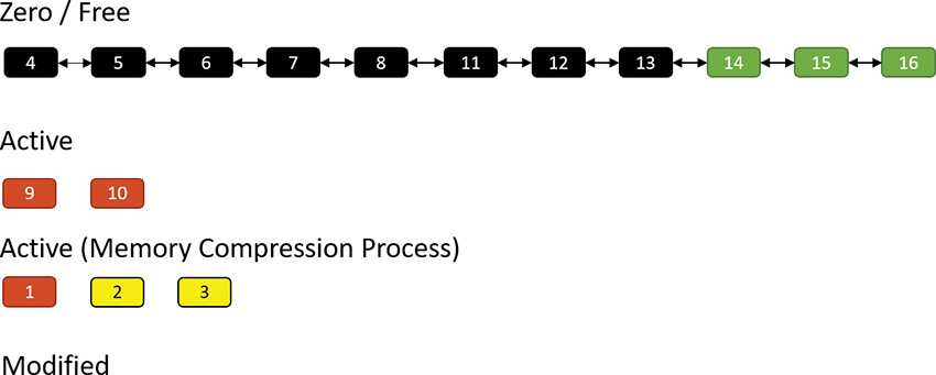
To get a sense of how memory compression works, let’s look at an illustrative example. Assume that at some point in time, the following physical pages exist:
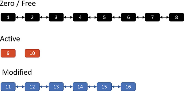
The zero and free page lists contain pages that have garbage and zeroes, respectively, and can be used to satisfy memory commits; for the sake of this discussion, we’ll treat them as one list. The active pages belong to various processes, while the modified pages have dirty data that has not yet been written to a page file, but can be soft-faulted without an I/O operation to a process working set if that process references a modified page.
Now assume the memory manager decides to trim the modified page list—for example, because it has become too large or the zero/free pages have become too small. Assume three pages are to be removed from the modified list. The memory manager compresses their contents into a single page (taken from the zero/free list):
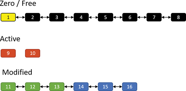
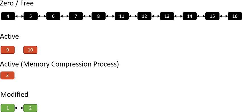
Pages 11, 12 and 13 are compressed into page 1. After that’s done, page 1 is no longer free and is in fact active, part of the working set of the memory compression process (described in the next section). Pages 11, 12, and 13 are no longer needed and move to the free list; the compression saved two pages:
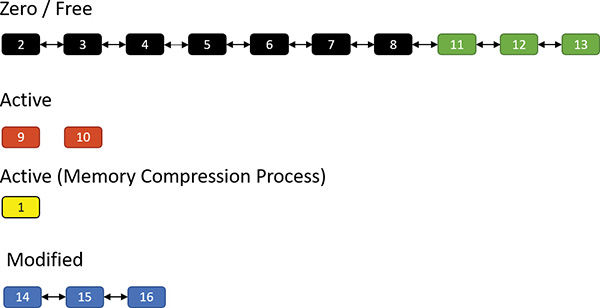
Suppose the same process repeats. This time, pages 14, 15, and 16 are compressed into (say) two pages (2 and 3) as shown here:
The result is that pages 2 and 3 join the working set of the memory compression process, while pages 14, 15, and 16 become free:
Suppose the memory manager later decides to trim the working set of the memory compression process. In that case, such pages are moved to the modified list because they contain data not yet written to a page file. Of course, they can at any time be soft-faulted back into their original process (decompressing in the process by using free pages). The following shows pages 1 and 2 being removed from the active pages of the memory compression process and moved to the modified list:
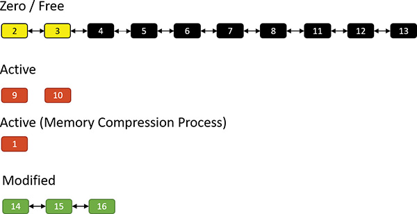
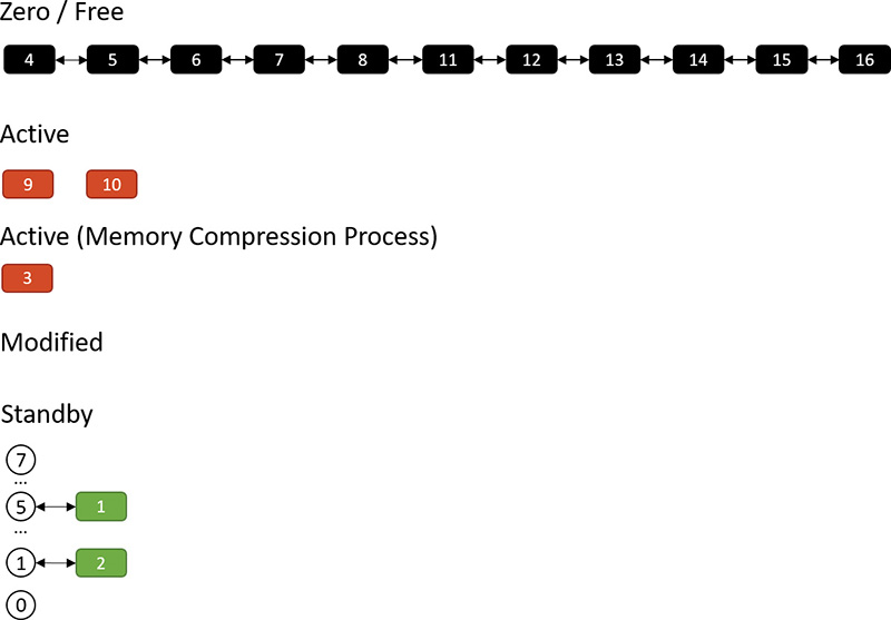
If memory becomes tight, the memory manager may decide to write the compressed modified pages to a page file:

Finally, after such pages have been written to a page file, they move to the standby list because their content is saved, so they can be repurposed if necessary. They can also be soft-faulted (as when they are part of the modified list) by decompressing them and moving the resulting pages to the active state under the relevant process working set. When in the standby list, they are attached to the appropriate sub-list, depending on their priority (as described in the “Page priority and rebalancing” section later in this chapter):
Compression architecture
The compression engine needs a “working area” memory to store compressed pages and the data structures that manage them. In Windows 10 versions prior to 1607, the user address space of the System process was used. Starting with Windows 10 Version 1607, a new dedicated process called Memory Compression is used instead. One reason for creating this new process was that the System process memory consumption looked high to a casual observer, which implied the system was consuming a lot of memory. That was not the case, however, because compressed memory does not count against the commit limit. Nevertheless, sometimes perception is everything.
The Memory Compression process is a minimal process, which means it does not load any DLLs.Rather, it just provides an address space to work with. It’s not running any executable image either—the kernel is just using its user mode address space. (See Chapter 3, “Processes and jobs,” for more information on minimal processes.)
![]() Note
Note
By design, Task Manager does not show the Memory Compression process in its details view, but Process Explorer does. Using a kernel debugger, the compression process image name is MemCompression.
For each store, the Store Manager allocates memory in regions with a configurable region size. Currently, the size used is 128 KB. The allocations are done by normal VirtualAlloc calls as needed. The actual compressed pages are stored in 16 byte chunks within a region. Naturally, a compressed page (4 KB) can span many chunks. Figure 5-44 shows a store with an array of regions and some of the data structures associated with managing such a store.
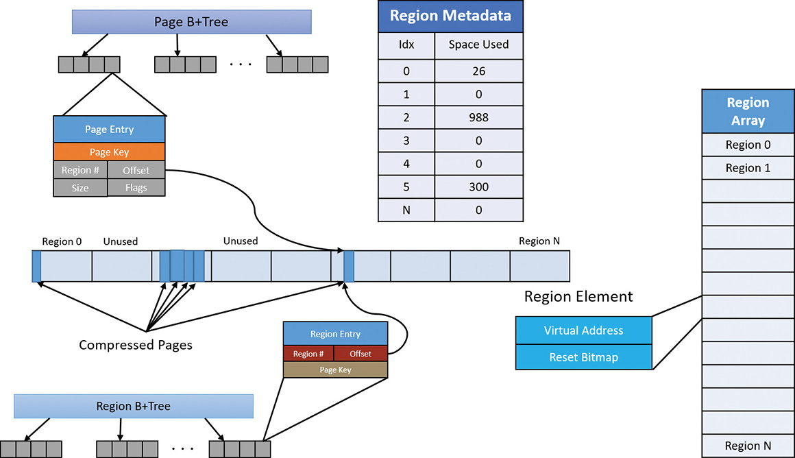
As shown in Figure 5-44, pages are managed with a B+Tree—essentially a tree where a node can have any number of children—where each page entry points to its compressed content within one of the regions. A store starts with zero regions, and regions are allocated and deallocated as needed. Regions are also associated with priorities, as described in the “Page priority and rebalancing” section later in this chapter.
Adding a page involves the following major steps:
1. If there is no current region with the page’s priority, allocate a new region, lock it in physical memory, and assign it the priority of the page to be added. Set the current region for that priority to the allocated region.
2. Compress the page and store it in the region, rounding up to the granularity unit (16 bytes). For example, if a page compresses to 687 bytes, it consumes 43 16-byte units (always rounding up). Compression is done on the current thread, with low CPU priority (7) to minimize interference. When decompression is needed, it’s performed in parallel using all available processors.
3. Update the page and region information in the Page and Region B+Trees.
4. If the remaining space in the current region is not large enough to store the compressed page, a new region is allocated (with the same page priority) and set as the current region for that priority.
Removing a page from the store involves the following steps:
1. Find the page entry in the Page B+Tree and the region entry in the Region B+Tree.
2. Remove the entries and update the space used in the region.
3. If the region becomes empty, deallocate the region.
Regions become fragmented over time as compressed pages are added and removed. The memory for a region is not freed until the region is completely empty. This means some kind of compaction is necessary to reduce memory waste. A compaction operation is lazily scheduled with aggressiveness depending on the amount of fragmentation. Region priorities are taken into account when consolidating regions.

Memory partitions
Traditionally, virtual machines (VMs) are used to isolate applications so that separate VMs can run completely isolated applications (or groups of applications) at least from a security standpoint. VMs cannot interact with each other, providing strong security and resource boundaries. Although this works, VMs have a high resource cost in terms of hardware that hosts the VMs and management costs. This gave a rise to container-based technologies, such as Docker. These technologies attempt to lower the barrier for isolation and resource management by creating sandbox containers that host applications, all on the same physical or virtual machine.
Creating such containers is difficult, as it would require kernel drivers that perform some form of virtualization on top of the regular Windows. Some of these drivers are the following (a single driver can encompass all these functionalities):
![]() File system (mini) filter that would create an illusion of an isolated file system
File system (mini) filter that would create an illusion of an isolated file system
![]() Registry virtualization driver, creating an illusion of a separate registry (
Registry virtualization driver, creating an illusion of a separate registry (CmRegisterCallbacksEx)
![]() Private object manager namespace, by utilizing silos (see Chapter 3 for more details)
Private object manager namespace, by utilizing silos (see Chapter 3 for more details)
![]() Process management for associating processes with the correct container by using process create/ notifications (
Process management for associating processes with the correct container by using process create/ notifications (PsSetCreateNotifyRoutineEx)
Even with these in place, some things are difficult to virtualize, specifically memory management. Each container may want to use its own PFN database, its own page file, and so on. Windows 10 (64-bit versions only) and Windows Server 2016 provide such possible memory control through Memory Partitions.
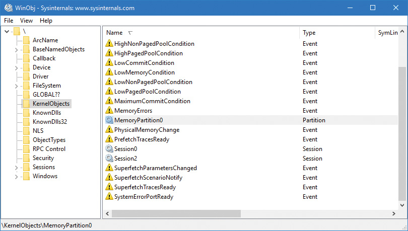
A memory partition consists of its own memory-related management structures, such as page lists (standby, modified, zero, free, etc.), commit charge, working set, page trimmer, modified page writer, zero-page thread, and so on, but isolated from other partitions. Memory partitions are represented in the system by Partition objects, which are securable, nameable objects (just like other executive objects). One partition always exists, called the System Partition, and it represents the system as a whole and is the ultimate parent of any explicitly created partition. The system partition’s address is stored in a global variable (MiSystemPartition) and its name is KernelObjectsMemoryPartition0, visible with tools such as WinObj from Sysinternals as shown in Figure 5-45.
All partition objects are stored in global list, where the current maximum partition count is 1024 (10 bits), because the partition index must be encoded in PTEs for quick access to partition information where applicable. One of these indices is the system partition and two other values are used as special sentinels, leaving 1021 partitions available.
Memory partitions can be created from user mode or kernel mode by using the NtCreatePartition internal (and undocumented) function; user mode callers must have the SeLockMemory privilege for the call to succeed. The function can accept a parent partition, which initial pages will come from and eventually return to, when the partition is destroyed; the system partition is the default parent if none is specified. NtCreatePartition delegates the actual work to the internal memory manager MiCreatePartition function.
An existing partition can be opened by name using NtOpenPartition (no special privilege required for this as the object can be protected by ACLs as usual). The actual manipulation of a partition is reserved for the NtManagePartition function. This is the function that can be used to add memory to the partition, add a paging file, copy memory from one partition to another, and generally obtain information about a partition.
Future scenarios may leverage the memory partitioning capability for specific processes (through job objects) to be associated with a partition, such as when exclusive control over physical memory may be beneficial. One such scenario slated for the Creators Update release is game mode (more information on game mode is included in Chapter 8 in Part 2).
Memory combining
The memory manager uses several mechanisms in an attempt to save as much RAM as possible, such as sharing pages for images, copy-on-write for data pages, and compression. In this section, we’ll take a look at yet another such mechanism called memory combining.
The general idea is simple: Find duplicates of pages in RAM and combine them into one, thus removing the rest of the duplicates. Clearly there are a few issues to resolve:
![]() What are the “best” pages to use as candidates for combining?
What are the “best” pages to use as candidates for combining?
![]() When is it appropriate to initiate memory combining?
When is it appropriate to initiate memory combining?
![]() Should combining be targeted at a particular process, a memory partition, or the entire system?
Should combining be targeted at a particular process, a memory partition, or the entire system?
![]() How can the combining process be made quick so it does not adversely impact normally executing code?
How can the combining process be made quick so it does not adversely impact normally executing code?
![]() If a writeable combined page is later modified by one of its clients, how would it get a private copy?
If a writeable combined page is later modified by one of its clients, how would it get a private copy?
We’ll answer these questions throughout this section, starting with the last. The copy-on-write mechanism is used here: as long as a combined page is not written to, do nothing. If a process tries to write to the page, make a private copy for the writing process, and remove the copy-on-write flag for that newly allocated private page.
![]() Note
Note
Page combining can be disabled by setting a DWORD value named DisablePageCombining to 1 in the HKLMSystemCurrentControlSetControlSession ManagerMemory Management registry key.
![]() Note
Note
In this section, the terms CRC and hash are used interchangeably. They indicate a statistically unique (with high probability) 64-bit number referencing a page’s contents.
The memory manager’s initialization routine, MmInitSystem, creates the system partition (see the previous section on memory partitions). Within the MI_PARTITION structure that describes a partition lies an array of 16 AVL trees that identify the duplicated pages. The array is sorted by the last 4 bits of a combined page CRC value. We’ll see in a moment how this fits into the algorithm.
Two special page types are called common pages. One includes an all zero bytes, and the other includes an all one bits (filled with the byte 0xFF); their CRC is calculated just once and stored. Such pages can easily be identified when scanning pages’ contents.
To initiate memory combining, the NtSetSystemInformation native API is called with the System-CombinePhysicalMemoryInformation system information class. The caller must have the SeProfile-SingleProcessPrivilege in its token, normally granted to the local administrators group. The argument to the API provides the following options through a combination of flags:
![]() Perform memory combining on the entire (system) partition or just the current process.
Perform memory combining on the entire (system) partition or just the current process.
![]() Search for common pages (all zeros or all ones) to combine only, or any duplicate pages regardless of content.
Search for common pages (all zeros or all ones) to combine only, or any duplicate pages regardless of content.
The input structure also provides an optional event handle that can be passed in, and if signaled (by another thread), will abort the page combining. Currently, the Superfetch service (see the section “SuperFetch” at the end of this chapter for more information) has a special thread, running in low priority (4) that initiates memory combining for the entire system partition when the user is away, or if the user is busy, every 15 minutes.
In the Creators Update, if the amount of physical memory is higher than 3.5 GB (3584 MB), most built-in Svchost-ed services host a single service in each Svchost process. This creates dozens of processes out of the box but removes the likelihood of one service affecting another (either because of some instability or security issues). In this scenario, the Service Control Manager (SCM) uses a new option of the memory combining API, and initiates page combining in each of the Svchost processes every three minutes by utilizing a thread pool timer running with base priority of 6 (ScPerformPageCombineOnServiceImages routine). The rationale is to try to reduce RAM consumption that may be higher than with fewer Svchost instances. Note that non-Svchost services are not page combined, nor are services running with per-user or private user accounts.
The MiCombineIdenticalPages routine is the actual entry point to the page combining process. For each NUMA node of the memory partition, it allocates and stores a list of pages with their CRC inside the page combing support (PCS) structure, which is the one managing all the needed information for the page combining operation. (That’s the one holding the AVL trees array mentioned earlier.) The requesting thread is the one doing the work; it should run on CPUs belonging to the current NUMA node, and its affinity is modified accordingly if needed. We’ll divide the memory combining algorithm into three stages to simplify the explanation: search, classification, and page sharing. The following sections assume that a complete page combining is requested (rather than for the current process) and for all pages (not just the common pages); the other cases are similar in principle, and somewhat simpler.
The search phase
The goal of this initial stage is to calculate the CRC of all the physical pages. The algorithm analyses each physical page that belongs to the active, modified, or standby list, skipping the zeroed and free pages (since they are effectively unused).
A good page candidate for memory combining should be an active non-shared page that belongs to a working set, and that should not map a paging structure. The candidate could be even in the standby or modified state, but needs to have a reference counter of 0. Basically, the system identifies three types of pages for combining: user process, paged pool, and session space. Other types of pages are skipped.
To correctly calculate the CRC of the page, the system should map the physical page to a system address (because the process context is mostly different from the calling thread, making the page inaccessible in low user-mode addresses) using a new system PTE. The CRC of the page is then calculated with a customized algorithm (MiComputeHash64 routine), and the system PTE freed (the page is now unmapped from system address space).
The classification phase
When all the hashes of the pages that belong to a NUMA node have been successfully calculated, the second part of the algorithm commences. The goal of this phase is to process each CRC/PFN entry in the list and organize them in a strategic way. The page sharing algorithm must minimize the process contexts switches, and be as fast as possible.
The MiProcessCrcList routine starts by sorting the CRC/PFN list by hash (using a quick sort algorithm). Another key data structure, combine block, is used to keep track of all the pages that share the same hash, and, more importantly, to store the new prototype PTE that will map the new combined page. Each CRC/PFN of the new sorted list is processed in order. The system needs to verify if the current hash is common (belongs to a zeroed or a complete-filled page) and if it’s equal to the previous or next hash (remember that the list is sorted). If this is not the case, the system checks if a combine block already exists in the PCS structure. If so, it means that a combined page has been already identified in a previous execution of the algorithm or in another node of the system. Otherwise it means that the CRC is unique and the page couldn’t be combined, and the algorithm continues to the next page in the list.
If the found common hash has never been seen before, the algorithm allocates a new empty combine block (used for the master PFN) and inserts it in a list used by the actual page-sharing code (next stage). Otherwise if the hash already existed (the page is not the master copy), a reference to the combine block is added in the current CRC/PFN entry.
At this point, the algorithm has prepared all the data that the page-sharing algorithm needs: a list of combine blocks used to store the master physical pages and their prototype PTEs, a list of CRC/PFN entries organized by the owning working set, and some physical memory needed to store the content of the new shared pages.
The algorithm then obtains the address of the physical page (that should exist, due to the initial check performed previously by the MiCombineIdenticalPages routine) and searches a data structure used to store all the pages that belongs to the specific working set (from now on we will call this structure WS CRC node). If this doesn’t exist, it allocates a new one and inserts it in another AVL tree. The CRC/PFN and virtual address of the page are linked together inside the WS CRC node.
After all the identified pages have been processed, the system allocates the physical memory for the new master shared pages (using an MDL), and processes each WS CRC node; for performance reasons, the candidate pages located inside the node are sorted by their original virtual address. The system is now ready to perform the actual page combining.
The page combining phase
The page combining phase starts with a WS CRC node structure that contains all the pages that belong to a specific working set and are all candidates for combining, and with a list of free combine blocks, used to store the prototype PTE and the actual shared page. The algorithm attaches to the target process and locks its working set (raising IRQL to dispatch level). In this way, it will be able to directly read and write each page without the need to remap it.
The algorithm processes every CRC/PFN entry in the list, but since it’s running at dispatch level IRQL and execution could take some time, it checks if the processor has some DPCs or scheduled items in its queue (by calling KeShouldYieldProcessor) before analyzing the next entry. If the answer is yes, the algorithm does the right thing and takes appropriate precautions to maintain state.
The actual page sharing strategy expects three possible scenarios:
![]() The page is active and valid, but it contains all zeroes, so rather than combining, it replaces its PTE with a demand-zero PTE. Recall that this is the initial state of normal VirtualAlloc-like memory allocation.
The page is active and valid, but it contains all zeroes, so rather than combining, it replaces its PTE with a demand-zero PTE. Recall that this is the initial state of normal VirtualAlloc-like memory allocation.
![]() The page is active and valid, but it is not zeroed out, meaning it has to be shared. The algorithm checks if the page has to be promoted as the master: if the CRC/PFN entry has a pointer to a valid combine block, it means that it’s not the master page; otherwise, the page is the master copy. The master page hash is rechecked and a new physical page assigned for the sharing. Otherwise, the already existing combine block is used (and its reference count incremented). The system is now ready to convert the private page into a shared one, and calls the
The page is active and valid, but it is not zeroed out, meaning it has to be shared. The algorithm checks if the page has to be promoted as the master: if the CRC/PFN entry has a pointer to a valid combine block, it means that it’s not the master page; otherwise, the page is the master copy. The master page hash is rechecked and a new physical page assigned for the sharing. Otherwise, the already existing combine block is used (and its reference count incremented). The system is now ready to convert the private page into a shared one, and calls the MiConvert-PrivateToProto routine to perform the actual job.
![]() The page is in the modified or standby list. In this case, it’s mapped to a system address as a valid page and its hash recalculated. The algorithm performs the same step as the previous scenario, with the only difference being that the PTE is converted from shared to prototype using the
The page is in the modified or standby list. In this case, it’s mapped to a system address as a valid page and its hash recalculated. The algorithm performs the same step as the previous scenario, with the only difference being that the PTE is converted from shared to prototype using the MiConvertStandbyToProto routine.
When the sharing of the current page ends, the system inserts the combine block of the master copy into the PCS structure. This is important because the combine block becomes the link between each private PTE and the combined page.
From private to shared PTE
The goal of MiConvertPrivateToProto is to convert a PTE of an active and valid page. If the routine detects that the prototype PTE inside the combine block is zero, it means that the master page must be created (together with the master shared prototype PTE). It then maps the free physical page into a system address and copies the content of the private page into the new shared one. Before actually creating the shared PTE, the system should free any page file reservation (see the section “Page file reservation” earlier in this chapter) and fill the PFN descriptor of the shared page. The shared PFN has the prototype bit set, and the PTE frame pointer set to the PFN of the physical page that contains the Prototype PTE. Most importantly, it has the PTE pointer set to the PTE located inside the combine block, but with the 63rd bit set to zero. This signifies to the system that the PFN belongs to a page that has been combined.
Next, the system needs to modify the PTE of the private page so that its target PFN is set to the shared physical page, its protection mask changed to copy-on-write, and the private page PTE is marked as valid. The prototype PTE inside the combine block is marked as a valid hardware PTE too: the content is identical to the new PTE of the private page. Finally, the page file space allocated for the private page is freed and the original PFN of the private page is marked as deleted. The TLB cache is flushed and the private process working set size is decremented by one page.
Otherwise (the prototype PTE inside the combine block is non-zero), it means that the private page should be a copy of the master one. Only the active PTE of the private page must be converted. The PFN of the shared page is mapped to a system address and the content of the two pages is compared. This is important because the CRC algorithm does not produce unique values in the general case. If the two pages don’t match, the function stops processing and returns. Otherwise, it unmaps the shared page and sets the page priority of the shared PFN to the higher of the two. Figure 5-46 shows the state where only a master page exists.

The algorithm now calculates the new invalid software prototype PTE that should be inserted into the process private page table. To do that, it reads the address of the hardware PTE that maps the shared page (located in the combine block), shifts it, and sets the Prototype and Combined bits. A check is made that the share count of the private PFN is 1. If it is not, processing is aborted. The algorithm writes the new software PTE in the private page table of the process and decrements the share count of the page table of the old private PFN (keep in mind that an active PFN always has a pointer to its page table). The target process working set size is decremented by one page and the TLB is flushed. The old private page is moved into the transition state, and its PFN is marked for deletion. Figure 5-47 shows two pages, where the new page points to the prototype PTE but is not yet valid.
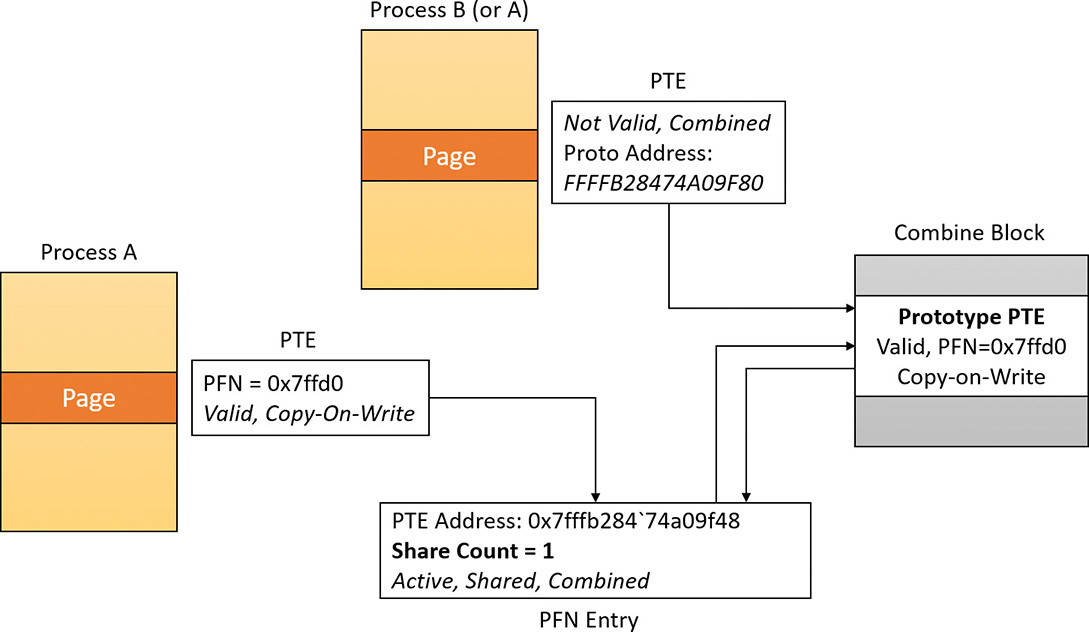
Finally, the system uses another trick to prevent working set trimming on the shared pages by simulating a page fault. That way the share count of the shared PFN is again incremented, and no fault would occur at a time the process will try to read the shared page. The end result is that the private PTE is again a valid hardware PTE. Figure 5-48 shows the effect of a soft page fault on the second page, making it valid and incrementing the share count.
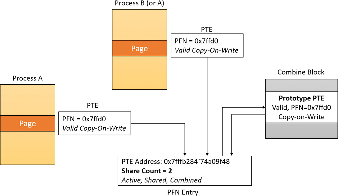
Combined pages release
When the system needs to free a particular virtual address, it first locates the address of the PTE that maps it. The pointed PFN of a combined page has the prototype and combined bits set. The free request for a combined PFN is managed exactly like the one for a prototype PFN. The only difference is that the system (if the combined bit is set) calls MiDecrementCombinedPte after processing the prototype PFN.
MiDecrementCombinedPte is a simple function that decrements the reference count of the combine block of the Prototype PTE. (Keep in mind that at this stage the PTE is in transition because the memory manager has already dereferenced the physical page that it maps. The share count of the physical page has already dropped to zero, and so the system put the PTE in transition.) If the reference count drops to zero, the prototype PTE will be freed, the physical page put in the free list, and the combine block returned to the combine free list of the PCS structure of the memory partition.
1. Start a kernel debugging session with a VM target (as described in Chapter 4, “Threads”).
2. Copy the MemCombine32.exe (for 32 bit targets) or MemCombine64.exe (for 64 bit targets), and MemCombineTest.exe executables from this book’s downloadable resources to the target machine.
3. Run MemCombineTest.exe on the target machine. You should see something like the following:
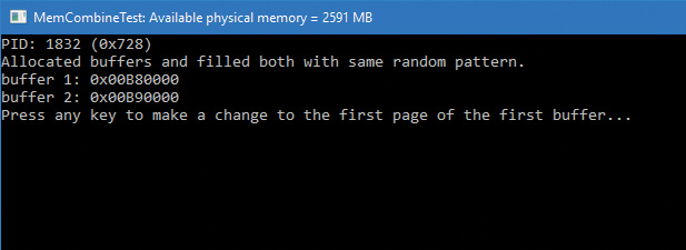
4. Note the two addresses shown. These are two buffers filled with a random generated pattern of bytes, repeated so that each page has the same content.
5. Break into the debugger. Locate the MemCombineTest process:
0: kd> !process 0 0 memcombinetest.exe
PROCESS ffffe70a3cb29080
SessionId: 2 Cid: 0728 Peb: 00d08000 ParentCid: 11c4
DirBase: c7c95000 ObjectTable: ffff918ede582640 HandleCount: <Data Not
Accessible>
Image: MemCombineTest.exe
6. Switch to the located process:
0: kd> .process /i /r ffffe70a3cb29080
You need to continue execution (press 'g' <enter>) for the context
to be switched. When the debugger breaks in again, you will be in
the new process context.
0: kd> g
Break instruction exception - code 80000003 (first chance)
nt!DbgBreakPointWithStatus:
fffff801'94b691c0 cc int 3
7. Use the !pte command to locate the PFN where the two buffers are stored:
0: kd> !pte b80000
VA 0000000000b80000
PXE at FFFFA25128944000 PPE at FFFFA25128800000 PDE at
FFFFA25100000028 PTE at FFFFA20000005C00
contains 00C0000025BAC867 contains 0FF00000CAA2D867 contains
00F000003B22F867 contains B9200000DEDFB867
pfn 25bac ---DA--UWEV pfn caa2d ---DA--UWEV pfn 3b22f ---DA--
UWEV pfn dedfb ---DA--UW-V
0: kd> !pte b90000
VA 0000000000b90000
PXE at FFFFA25128944000 PPE at FFFFA25128800000 PDE at
FFFFA25100000028 PTE at FFFFA20000005C80
contains 00C0000025BAC867 contains 0FF00000CAA2D867 contains
00F000003B22F867 contains B9300000F59FD867
pfn 25bac ---DA--UWEV pfn caa2d ---DA--UWEV pfn 3b22f ---DA--
UWEV pfn f59fd ---DA--UW-V
8. Notice the PFN values are different, indicating that these pages are mapped to different physical addresses. Resume the target.
9. On the target, open an elevated command window, navigate to the directory where you copied MemCombine(32/64), and run it. The tool forces a full memory combining, which may take a few seconds.
10. When it’s finished, break into the debugger again. Repeat steps 6 and 7. You should see the PFNs change:
1: kd> !pte b80000
VA 0000000000b80000
PXE at FFFFA25128944000 PPE at FFFFA25128800000 PDE at
FFFFA25100000028 PTE at FFFFA20000005C00
contains 00C0000025BAC867 contains 0FF00000CAA2D867 contains
00F000003B22F867 contains B9300000EA886225
pfn 25bac ---DA--UWEV pfn caa2d ---DA--UWEV pfn 3b22f ---DA--
UWEV pfn ea886 C---A--UR-V
1: kd> !pte b90000
VA 0000000000b90000
PXE at FFFFA25128944000 PPE at FFFFA25128800000 PDE at
FFFFA25100000028 PTE at FFFFA20000005C80
contains 00C0000025BAC867 contains 0FF00000CAA2D867 contains
00F000003B22F867 contains BA600000EA886225
pfn 25bac ---DA--UWEV pfn caa2d ---DA--UWEV pfn 3b22f ---DA--
UWEV pfn ea886 C---A--UR-V
11. Notice the PFN values are the same, meaning the pages are mapped to the exact same address in RAM. Also note the C flag in the PFN, indicating copy-on-write.
12. Resume the target and press any key in the MemCombineTest window. This changes a single byte in the first buffer.
13. Break into the target again and repeat steps 6 and 7 yet again:
1: kd> !pte b80000
VA 0000000000b80000
PXE at FFFFA25128944000 PPE at FFFFA25128800000 PDE at
FFFFA25100000028 PTE at FFFFA20000005C00
contains 00C0000025BAC867 contains 0FF00000CAA2D867 contains
00F000003B22F867 contains B9300000813C4867
pfn 25bac ---DA--UWEV pfn caa2d ---DA--UWEV pfn 3b22f ---DA--
UWEV pfn 813c4 ---DA--UW-V
1: kd> !pte b90000
VA 0000000000b90000
PXE at FFFFA25128944000 PPE at FFFFA25128800000 PDE at
FFFFA25100000028 PTE at FFFFA20000005C80
contains 00C0000025BAC867 contains 0FF00000CAA2D867 contains
00F000003B22F867 contains BA600000EA886225
pfn 25bac ---DA--UWEV pfn caa2d ---DA--UWEV pfn 3b22f ---DA--
UWEV pfn ea886 C---A--UR-V
14. The PFN for the first buffer has changed, and the copy-on-write flag was removed. The page has changed and was relocated to a different address in RAM.
Memory enclaves
Threads executing in a process have access to the entire process address space (as determined by page protection, which can be changed). This is desirable most of the time; however, in case malicious code manages to get itself injected into a process, it has the exact same power. It can freely read data that may contain sensitive information and even change it.
Intel has created a technology called Intel Software Guard Extensions (SGX) that allows the creation of protected memory enclaves—secure zones in a process address space where code and data are protected by the CPU from code running outside the enclave. Conversely, code running inside an enclave has full (normal) access to process address space outside the enclave. Naturally, the protection extends to access from other processes and even code running in kernel mode. A simplified diagram of memory enclaves is shown in Figure 5-49.
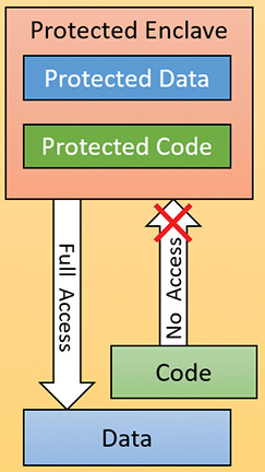
Intel SGX is supported by sixth generation Core processors (“Skylake”) and later generations. Intel has its own SDK for application developers that can be used on Windows 7 and later systems (64 bit only). Starting with Windows 10 version 1511 and Server 2016, Windows provide an abstraction using Windows API functions that removes the need to use Intel’s SDK. Other CPU vendors may create similar solutions in the future, and these will also be wrapped by the same API, providing a relatively portable layer for application developers to use for creating and populating enclaves.
![]() Note
Note
Not all sixth generation Core processors support SGX. Also, an appropriate BIOS update must be installed on the system for SGX to work. Consult the Intel SGX documentation for more information. The Intel SGX website can be found at https://software.intel.com/en-us/sgx.
![]() Note
Note
At the time of this writing, Intel produced two versions of SGX (versions 1.0 and 2.0). Windows currently supports version 1.0 only. The differences are outside the scope of this book; consult the SGX documentation for more information.
![]() Note
Note
Current SGX versions do not support enclaves in ring 0 (kernel mode). Only ring 3 (user mode) enclaves are supported.
Programmatic interface
From an application developer’s perspective, creating and working with an enclave consists of the following steps. (The internal details are described in the following sections.)
1. Initially the program should determine whether memory enclaves are supported by calling IsEnclaveTypeSupported, passing a value representing the enclave technology, which currently can only be ENCLAVE_TYPE_SGX.
2. A new enclave is created by calling the CreateEnclave function, which is similar in its arguments to VirtualAllocEx. For example, it’s possible to create an enclave in a different process than the caller process. The complication in this function is the need to provide a vendor-specific configuration structure, which for Intel means a 4 KB data structure called SGX Enclave Control Structure (SECS), which Microsoft does not define explicitly. Instead, developers are expected to create their own structure based on the particular technology used and defined in its documentation.
3. Once an empty enclave is created, the next step is to populate the enclave with code and data from outside of the enclave. This is accomplished by calling LoadEnclaveData where an external memory to the enclave is used to copy data to the enclave. Multiple calls to LoadEnclaveData may be used to populate the enclave.
4. The last step that is required to “activate” the enclave is achieved with the InitializeEnclave function. At that point, code that was configured to execute within the enclave can start executing.
5. Unfortunately, executing the code in the enclave is not wrapped by the API. Direct use of assembly language is required. The EENTER instruction transfers execution to the enclave and the EEXIT instruction causes return to the calling function. Abnormal termination of the enclave execution is also possible with Asynchronous Enclave Exit (AEX), such as due to a fault. The exact details are beyond the scope of this book, as they are not Windows-specific. Consult the SGX documentation to get the fine details.
6. Finally, to destroy the enclave, a normal VirtualFree(Ex) function can be used on the pointer to the enclave obtained in CreateEnclave.
Memory enclave initializations
During boot, Winload (the Windows Boot Loader) calls OslEnumerateEnclavePageRegions, which first checks if SGX is supported using the CPUID instruction. If it is, it issues instructions to enumerate Enclave Page Cache (EPC) descriptors. EPC is the protected memory provided by the processor for creating and using enclaves. For each enumerated EPC, OslEnumerateEnclavePageRegions calls BlMm- AddEnclavePageRange to add the page range information to a sorted list of memory descriptors with a type value of LoaderEnclaveMemory. This list is eventually stored in the MemoryDescriptorListHead member of the LOADER_PARAMETER_BLOCK structure used to pass information from the boot loader to the kernel.
During phase 1 initialization, the memory manager routine MiCreateEnclaveRegions is called to create an AVL tree for the discovered enclave regions (allowing quick lookups when needed); the tree is stored in the MiState.Hardrware.EnclaveRegions data member. The kernel adds a new enclave page list, and a special flag passed to MiInsertPageInFreeOrZeroedList enables functionality to utilize this new list. However, since the memory manager has actually run out of list identifiers (3 bits are used for a maximum of 8 values, all taken), the kernel actually identifies these pages as being “bad” pages currently suffering an in-page error. The memory manager knows never to use bad pages, so calling enclave pages “bad” keeps them from being used by normal memory management operations, and so such pages end up in the bad page list.
Enclave construction
The CreateEnclave API ends up calling NtCreateEnclave in the kernel. As noted, a SECS structure must be passed in, documented by Intel SGX as shown in Table 5-24.
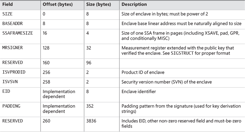
NtCreateEnclave first checks if memory enclaves are supported by looking at the root of the AVL tree (not by using the slower CPUID instruction). It then creates a copy of the passed-in structure (as is usual for kernel functions obtaining data from user mode) and attaches to the target process (KeStackAttachProcess) if the enclave is to be created in a different process than the caller’s. Then it transfers control to MiCreateEnclave to begin the actual work.
The first thing MiCreateEnclave does is allocate the Address Windowing Extension (AWE) information structure that AWE APIs also utilize. This is because similar to the AWE functionality, an enclave allows a user-mode application to directly have access over physical pages (that is to say, the physical pages that are EPC pages based on the detection described earlier). Anytime a user-mode application has such direct control over physical pages, AWE data structures and locks must be used. This data structure is stored in the AweInfo field of the EPROCESS structure.
Next, MiCreateEnclave calls MiAllocateEnclaveVad to allocate an enclave-type VAD describing the enclave virtual memory range. This VAD has the VadAwd flag (as all AWE VADs) but also an additional Enclave flag, to differentiate it from a true AWE VAD. Finally, as part of VAD allocation, this is where the user-mode address for the enclave memory will be chosen (if not explicitly specified in the original CreateEnclave call).
The next step in MiCreateEnclave is to acquire an enclave page regardless of the enclave size or initial commitment. This is because, as per Intel’s SGX documentation, all enclaves require at least a one-page control structure to be associated with them. MiGetEnclavePage is used to obtain the required allocation. This function simply scans the enclave page list described earlier, and extracts one page as needed. The returned page is mapped using a system PTE stored as part of the enclave VAD; the MiInitializeEnclavePfn function sets up the related PFN data structure and marks it Modified and ActiveAndValid.
There are no actual bits that would help you differentiate this enclave PFN from any other active region of memory (such as non-paged pool). This is where the enclave regions AVL tree comes into play, and MI_PFN_IS_ENCLAVE is a function that the kernel uses whenever it needs to check if a PFN is indeed describing an EPC region.
With the PFN initialized, the system PTE is now converted to a final global kernel PTE, and its resulting virtual address is computed. The final step in MiCreateEnclave is to call KeCreateEnclave, which will now do the low-level kernel enclave creation steps, including communication with the actual SGX hardware implementation. One job that KeCreateEnclave is responsible for is filling in the base address required by the SECS structure if the caller did not specify one, as it must be set in the SECS structure before communicating with the SGX hardware to create an enclave.
Loading data into an enclave
Once an enclave has been created, it’s time to load information into it. The LoadEnclaveData function is exposed for that purpose. The function merely forwards the request to the underlying executive function, NtLoadEnclaveData. The function resembles a combination of a memory copy operation with some VirtualAlloc attributes (such as page protection).
If the enclave created with CreateEnclave doesn’t yet have any committed enclave pages, they must first be obtained, which will result in zeroed out memory being added to the enclave, which can then be filled with non-zero memory from outside the enclave. Otherwise, if an initial pre-committed initialization size was passed in, then the enclave’s pages can directly be filled in with non-zero memory from outside of the enclave.
Because enclave memory is described by a VAD, many of the traditional memory management APIs will function, at least partly, on this memory as well. For example, calling VirtualAlloc (ending up in NtAllocateVirtualMemory) on such an address with the MEM_COMMIT flag will result in MiCommitEnclavePages being called, which will validate that the protection mask for the new pages is compatible (i.e., a combination of read, write, and/or execute, without any special caching or write combining flags), and then call MiAddPagesToEnclave, passing a pointer to the enclave VAD associated with the address range, the protection mask that was specified to VirtualAlloc, and the PTE addresses that correspond to the virtual address range being committed.
MiAddPagesToEnclave first checks if the enclave VAD has any existing EPC pages associated with it, and if there’s enough of them to satisfy the commit. If not, MiReserveEnclavePages is called to obtain a sufficient amount. MiReserveEnclavePages looks at the current enclave page list and counts the total. If there aren’t enough physical EPC pages provided by the processor (based on the information obtained at boot), the function fails. Otherwise, it calls MiGetEnclavePage in a loop for the required amount of pages.
For each PFN entry that is retrieved, it is linked into the PFN array in the enclave VAD. Essentially, this means that once an enclave PFN is removed from the enclave page list and put into an active state, the enclave VAD acts as the list of active enclave PFNs.
Once the required committed pages have been obtained, MiAddPagesToEnclave translates the page protection passed to LoadEnclaveData into their SGX equivalents. Next, it reserves the appropriate number of system PTEs to hold paging information for each EPC pages that will be required. With this information in hand, it will eventually call KeAddEnclavePage that calls the SGX hardware to do the actual page adding.
One special page protection attribute is PAGE_ENCLAVE_THREAD_CONTROL, which indicates the memory is for a Thread Control Structure (TCS) defined by SGX. Each TCS represents a different thread that can execute independently within the enclave.
NtLoadEnclaveData validates parameters and then calls MiCopyPagesIntoEnclave to do the actual work, which may require getting committed pages as described earlier.
Initializing an enclave
Now that the enclave has been created and data has been transferred into it, there is another last step to perform before actual code in the enclave can execute. InitializeEnclave must be called to notify SGX that the enclave is in its final state before execution can begin. InitializeEnclave requires two SGX-specific structures to be passed in (SIGSTRUCT and EINITTOKEN; see the SGX documentation for the details).
The executive function NtInitializeEnclave called by InitializeEnclave does some parameter validation and makes sure the enclave VAD obtained has the correct attributes and then passed the structures along to the SGX hardware. Note that an enclave can only be initialized once.
The final step would be to use the Intel assembly instruction EENTER to start code execution (again, see the SGX documentation for the details).
Proactive memory management (SuperFetch)
Traditional memory management in operating systems has focused on the demand-paging model discussed thus far, with some advances in clustering and prefetching so that disk I/O can be optimized at the time of the demand-page fault. Client versions of Windows, however, include a significant improvement in the management of physical memory with the implementation of SuperFetch, a memory management scheme that enhances the least–recently accessed approach with historical file access information and proactive memory management.
The standby list management in older versions of Windows had two limitations. First, the prioritization of pages relies only on the recent past behavior of processes and does not anticipate their future memory requirements. Second, the data used for prioritization is limited to the list of pages owned by a process at any given point in time. These shortcomings can result in scenarios in which the computer is left unattended for a brief period of time, during which a memory-intensive system application runs (doing work such as an antivirus scan or a disk defragmentation) and then causes subsequent interactive application use (or launch) to be sluggish. The same thing can happen when a user purposely runs a data- and/or memory-intensive application and then returns to use other programs, which appear to be significantly less responsive.
This decline in performance occurs because the memory-intensive application forces the code and data that active applications had cached in memory to be overwritten by the memory-intensive activities—applications perform sluggishly as they have to request their data and code from disk. Client versions of Windows take a big step toward resolving these limitations with SuperFetch.
Components
SuperFetch has several components in the system that work hand in hand to proactively manage memory and limit the impact on user activity when SuperFetch is performing its work. These components include the following:
![]() Tracer The tracer mechanisms are part of a kernel component (Pf) that allows SuperFetch to query detailed page-usage, session, and process information at any time. SuperFetch also uses the
Tracer The tracer mechanisms are part of a kernel component (Pf) that allows SuperFetch to query detailed page-usage, session, and process information at any time. SuperFetch also uses the FileInfo mini-filter driver (%SystemRoot%System32DriversFileinfo.sys) to track file usage.
![]() Trace collector and processor This collector works with the tracing components to provide a raw log based on the tracing data that has been acquired. This tracing data is kept in memory and handed off to the processor. The processor then hands the log entries in the trace to the agents, which maintain history files (described next) in memory and persist them to disk when the service stops, such as during a reboot.
Trace collector and processor This collector works with the tracing components to provide a raw log based on the tracing data that has been acquired. This tracing data is kept in memory and handed off to the processor. The processor then hands the log entries in the trace to the agents, which maintain history files (described next) in memory and persist them to disk when the service stops, such as during a reboot.
![]() Agents SuperFetch keeps file page access information in history files, which keep track of virtual offsets. Agents group pages by attributes, such as the following:
Agents SuperFetch keeps file page access information in history files, which keep track of virtual offsets. Agents group pages by attributes, such as the following:
• Page access while the user was active
• Page access by a foreground process
• Hard fault while the user was active
• Page access during an application launch
• Page access upon the user returning after a long idle period
![]() Scenario manager This component, also called the context agent, manages the three SuperFetch scenario plans: hibernation, standby, and fast-user switching. The kernel-mode part of the scenario manager provides APIs for initiating and terminating scenarios, managing the current scenario state, and associating tracing information with these scenarios.
Scenario manager This component, also called the context agent, manages the three SuperFetch scenario plans: hibernation, standby, and fast-user switching. The kernel-mode part of the scenario manager provides APIs for initiating and terminating scenarios, managing the current scenario state, and associating tracing information with these scenarios.
![]() Rebalancer Based on the information provided by the SuperFetch agents, as well as the current state of the system (such as the state of the prioritized page lists), the rebalancer—a specialized agent in the
Rebalancer Based on the information provided by the SuperFetch agents, as well as the current state of the system (such as the state of the prioritized page lists), the rebalancer—a specialized agent in the Superfetch user-mode service—queries the PFN database and reprioritizes it based on the associated score of each page, thus building the prioritized standby lists. The rebalancer can also issue commands to the memory manager that modify the working sets of processes on the system, and it is the only agent that actually takes action on the system. Other agents merely filter information for the rebalancer to use in its decisions. In addition to reprioritization, the rebalancer initiates prefetching through the prefetcher thread, which uses FileInfo and kernel services to preload memory with useful pages.
All these components use facilities inside the memory manager that allow for the querying of detailed information about the state of each page in the PFN database, the current page counts for each page list and prioritized list, and more. Figure 5-50 shows an architectural diagram of SuperFetch’s multiple components. SuperFetch components also use prioritized I/O to minimize user impact. (See Chapter 8 in Part 2 for more on I/O priority.)
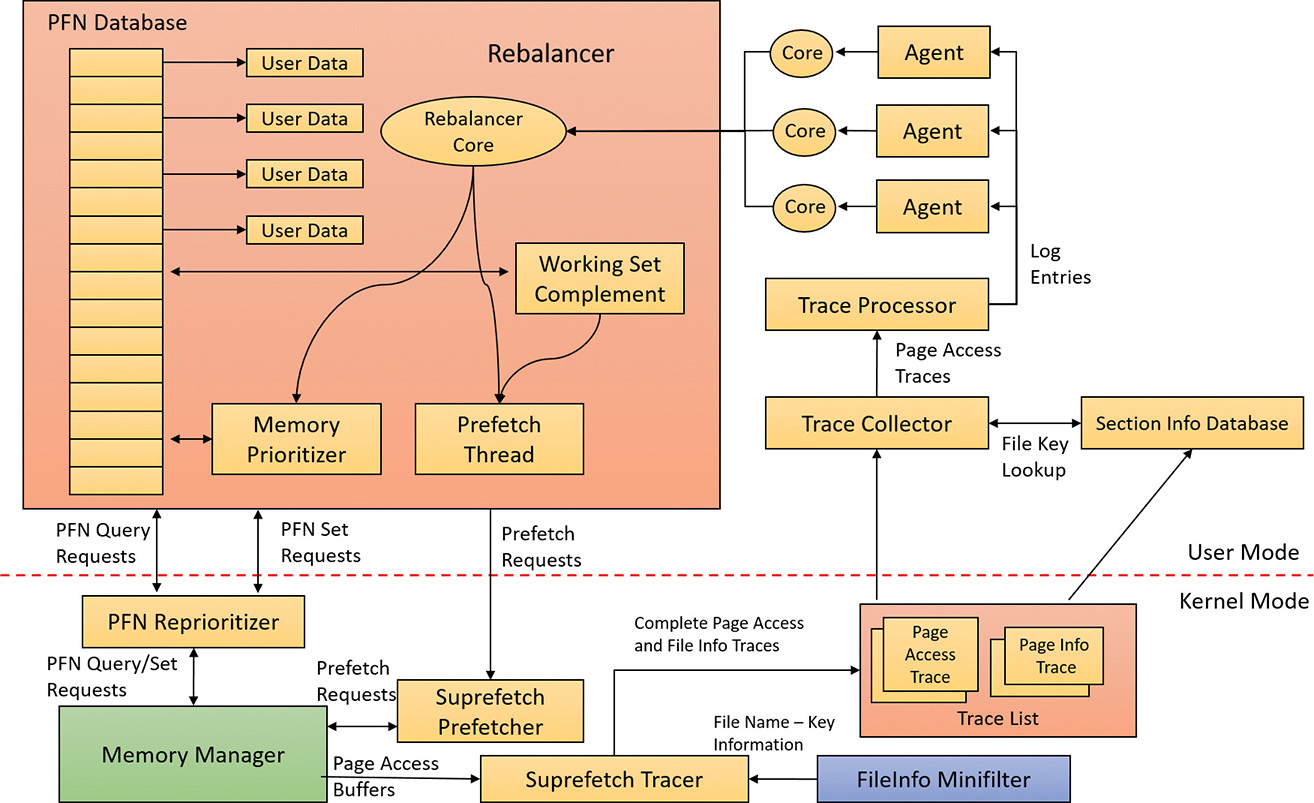
Tracing and logging
SuperFetch makes most of its decisions based on information that has been integrated, parsed, and post-processed from raw traces and logs, making these two components among the most critical. Tracing is like ETW in some ways because it uses certain triggers in code throughout the system to generate events, but it also works in conjunction with facilities already provided by the system, such as power-manager notification, process callbacks, and file-system filtering. The tracer also uses traditional page-aging mechanisms that exist in the memory manager, as well as newer working-set aging and access tracking implemented for SuperFetch.
SuperFetch always keeps a trace running and continuously queries trace data from the system, which tracks page usage and access through the memory manager’s access bit tracking and working-set aging. To track file-related information, which is as critical as page usage because it allows prioritization of file data in the cache, SuperFetch leverages existing filtering functionality with the addition of the FileInfo driver. (See Chapter 6 for more information on filter drivers.) This driver sits on the file-system device stack and monitors access and changes to files at the stream level, which provides it with fine-grained understanding of file access. (For more information on NTFS data streams, see Chapter 13 in Part 2.) The main job of the FileInfo driver is to associate streams—identified by a unique key, currently implemented as the FsContext field of the respective file object—with file names so that the user-mode Superfetch service can identify the specific file stream and offset that a page in the standby list belonging to a memory-mapped section is associated with. It also provides the interface for prefetching file data transparently, without interfering with locked files and other file-system state. The rest of the driver ensures that the information stays consistent by tracking deletions, renaming operations, truncations, and the reuse of file keys by implementing sequence numbers.
At any time during tracing, the rebalancer might be invoked to repopulate pages differently. These decisions are made by analyzing information such as the distribution of memory within working sets, the zero page list, the modified page list and the standby page lists, the number of faults, the state of PTE access bits, the per-page usage traces, current virtual address consumption, and working set size.
A given trace can be a page-access trace, in which the tracer uses the access bit to keep track of which pages were accessed by the process (both file page and private memory). Or, it can be a name-logging trace, which monitors the file name–to–file key mapping updates to the actual file on disk. These allow SuperFetch to map a page associated with a file object.
Although a SuperFetch trace only keeps track of page accesses, the Superfetch service processes this trace in user mode and goes much deeper, adding its own richer information such as where the page was loaded from (for example, in resident memory or a hard page fault), whether this was the initial access to that page, and what the rate of page access actually is. Additional information, such as the system state, is also kept, as well as information about recent scenarios in which each traced page was last referenced. The generated trace information is kept in memory through a logger into data structures, which—in the case of page-access traces—identify traces, a virtual address–to–working set pair, or, in the case of a name-logging trace, a file-to-offset pair. SuperFetch can thus keep track of which range of virtual addresses for a given process have page-related events and which range of offsets for a given file have similar events.
Scenarios
One aspect of SuperFetch that is distinct from its primary page reprioritization and prefetching mechanisms (covered in more detail in the next section) is its support for scenarios, which are specific actions on the machine for which SuperFetch strives to improve the user experience. These scenarios are as follows:
![]() Hibernation The goal of hibernation is to intelligently decide which pages are saved in the hibernation file other than the existing working-set pages. The idea is to minimize the amount of time it takes for the system to become responsive after a resume.
Hibernation The goal of hibernation is to intelligently decide which pages are saved in the hibernation file other than the existing working-set pages. The idea is to minimize the amount of time it takes for the system to become responsive after a resume.
![]() Standby The goal of standby is to completely remove hard faults after resume. Because a typical system can resume in less than 2 seconds, but can take 5 seconds to spin up the hard drive after a long sleep, a single hard fault could cause such a delay in the resume cycle. SuperFetch prioritizes pages needed after a standby to remove this chance.
Standby The goal of standby is to completely remove hard faults after resume. Because a typical system can resume in less than 2 seconds, but can take 5 seconds to spin up the hard drive after a long sleep, a single hard fault could cause such a delay in the resume cycle. SuperFetch prioritizes pages needed after a standby to remove this chance.
![]() Fast user switching The goal of fast user switching is to keep an accurate priority and understanding of each user’s memory. That way, switching to another user will cause the user’s session to be immediately usable, and won’t require a large amount of lag time to allow pages to be faulted in.
Fast user switching The goal of fast user switching is to keep an accurate priority and understanding of each user’s memory. That way, switching to another user will cause the user’s session to be immediately usable, and won’t require a large amount of lag time to allow pages to be faulted in.
Each of these scenarios has different goals, but all are centered around the main purpose of minimizing or removing hard faults.
Scenarios are hardcoded, and SuperFetch manages them through the NtSetSystemInformation and NtQuerySystemInformation APIs that control system state. For SuperFetch purposes, a special information class, SystemSuperfetchInformation, is used to control the kernel-mode components and to generate requests such as starting, ending, and querying a scenario or associating one or more traces with a scenario.
Each scenario is defined by a plan file, which contains, at minimum, a list of pages associated with the scenario. Page priority values are also assigned according to certain rules (described next). When a scenario starts, the scenario manager is responsible for responding to the event by generating the list of pages that should be brought into memory and at which priority.
Page priority and rebalancing
You’ve already seen that the memory manager implements a system of page priorities to define which standby list pages will be repurposed for a given operation and in which list a given page will be inserted. This mechanism provides benefits when processes and threads have associated priorities—for example, ensuring that a defragmenter process doesn’t pollute the standby page list and/or steal pages from an interactive foreground process. But its real power is unleashed through SuperFetch’s page-prioritization schemes and rebalancing, which don’t require manual application input or hardcoded knowledge of process importance.
SuperFetch assigns page priority based on an internal score it keeps for each page, part of which is based on frequency-based usage. This usage counts how many times a page was used in given relative time intervals, such as by hour, day, or week. The system also keeps track of time of use, recording how long it’s been since a given page was accessed. Finally, data such as where this page comes from (which list) and other access patterns is used to compute this score.
The score is translated into a priority number, which can be anywhere from 1 to 6. (A priority of 7 is used for another purpose, described later.) Going down each level, the lower standby page list priorities are repurposed first, as shown in the “Viewing the prioritized standby lists” experiment. Priority 5 is typically used for normal applications, while priority 1 is meant for background applications that third-party developers can mark as such. Finally, priority 6 is used to keep a certain number of high-importance pages as far away as possible from repurposing. The other priorities are a result of the score associated with each page.
Because SuperFetch “learns” a user’s system, it can start from scratch with no existing historical data and slowly build an understanding of the different page accesses associated with the user. However, this would result in a significant learning curve whenever a new application, user, or service pack was installed. Instead, by using an internal tool, Windows can pre-train SuperFetch to capture SuperFetch data and then turn it into prebuilt traces. These prebuilt traces were generated by the SuperFetch team, who traced common usages and patterns that all users will probably encounter, such as clicking the Start menu, opening Control Panel, or using the File Open/Save dialog box. This trace data was then saved to history files (which ship as resources in Sysmain.dll) and is used to prepopulate the special priority 7 list. This list is where the most critical data is placed and is rarely repurposed. Pages at priority 7 are file pages kept in memory even after the process has exited and even across reboots (by being repopulated at the next boot). Finally, pages with priority 7 are static, in that they are never reprioritized, and SuperFetch will never dynamically load pages at priority 7 other than the static pretrained set.
The prioritized list is loaded into memory (or prepopulated) by the rebalancer, but the actual act of rebalancing is handled by both SuperFetch and the memory manager. As shown, the prioritized standby page list mechanism is internal to the memory manager, and decisions as to which pages to throw out first and which to protect are innate, based on the priority number. The rebalancer does its job not by manually rebalancing memory but by reprioritizing it, which causes the memory manager to perform the needed tasks. The rebalancer is also responsible for reading the actual pages from disk, if needed, so that they are present in memory (prefetching). It then assigns the priority that is mapped by each agent to the score for each page, and the memory manager ensures that the page is treated according to its importance.
The rebalancer can take action without relying on other agents—for example, if it notices that the distribution of pages across paging lists is suboptimal or that the number of repurposed pages across different priority levels is detrimental. The rebalancer can also trigger working-set trimming, which might be required for creating an appropriate budget of pages that will be used for SuperFetch prepopulated cache data. The rebalancer will typically take low-utility pages—such as those that are already marked as low priority, that are zeroed, or that have valid content but not in any working set and have been unused—and build a more useful set of pages in memory, given the budget it has allocated itself. After the rebalancer has decided which pages to bring into memory and at which priority level they need to be loaded (as well as which pages can be thrown out), it performs the required disk reads to prefetch them. It also works in conjunction with the I/O manager’s prioritization schemes so that I/Os are performed with very low priority and do not interfere with the user.
The memory consumption used by prefetching is backed by standby pages. As described in the discussion of page dynamics, standby memory is available memory because it can be repurposed as free memory for another allocator at any time. In other words, if SuperFetch is prefetching the wrong data, there is no real impact on the user because that memory can be reused when needed and doesn’t actually consume resources.
Finally, the rebalancer also runs periodically to ensure that pages it has marked as high priority have actually been recently used. Because these pages will rarely (sometimes never) be repurposed, it is important not to waste them on data that is rarely accessed but may have appeared to be frequently accessed during a certain period. If such a situation is detected, the rebalancer runs again to push those pages down in the priority lists.
A special agent called the application launch agent is involved in a different kind of prefetching mechanism, which attempts to predict application launches and builds a Markov chain model that describes the probability of certain application launches given the existence of other application launches within a time segment. These time segments are divided across four different periods of roughly 6 hours each—morning, noon, evening, and night—and by weekday or weekend. For example, if on Saturday and Sunday evening a user typically launches Outlook after having launched Word, the application launch agent will likely prefetch Outlook based on the high probability of it running after Word during weekend evenings.
Because systems today have sufficiently large amounts of memory—on average more than 2 GB (although SuperFetch works well on low-memory systems, too)—the actual real amount of memory that frequently used processes on a machine need resident for optimal performance ends up being a manageable subset of their entire memory footprint. Often, SuperFetch can fit all the pages required into RAM. When it can’t, technologies such as ReadyBoost and ReadyDrive can further prevent disk usage.
Robust performance
A final performance-enhancing functionality of SuperFetch is called robustness, or robust performance. This component—managed by the user-mode Superfetch service but ultimately implemented in the kernel (Pf routines)—watches for specific file I/O access that might harm system performance by populating the standby lists with unneeded data. For example, if a process were to copy a large file across the file system, the standby list would be populated with the file’s contents, even though that file might never be accessed again (or not for a long period of time). This would throw out any other data within that priority—and if this was an interactive and useful program, chances are its priority would be at least 5.
SuperFetch responds to two specific kinds of I/O access patterns:
![]() Sequential file access With this type of I/O access pattern, the system goes through all the data in a file.
Sequential file access With this type of I/O access pattern, the system goes through all the data in a file.
![]() Sequential directory access With this type of I/O access, the system goes through every file in a directory.
Sequential directory access With this type of I/O access, the system goes through every file in a directory.
When SuperFetch detects that a certain amount of data past an internal threshold has been populated in the standby list as a result of this kind of access, it applies aggressive deprioritization (called robustion) to the pages being used to map this file. This occurs within the targeted process only so as not to penalize other applications. These pages, which are said to be robusted, essentially become reprioritized to priority 2.
Because this component of SuperFetch is reactive and not predictive, it does take some time for the robustion to kick in. SuperFetch will therefore keep track of this process for the next time it runs. Once SuperFetch has determined that it appears that this process always performs this kind of sequential access, it remembers this and robusts the file pages as soon as they’re mapped instead of waiting for the reactive behavior. At this point, the entire process is now considered robusted for future file access.
Just by applying this logic, however, SuperFetch could potentially hurt many legitimate applications or user scenarios that perform sequential access in the future. For example, by using the Sysinternals Strings.exe utility, you can look for a string in all executables that are part of a directory. If there are many files, SuperFetch would likely perform robustion. Now, next time you run Strings.exe with a different search parameter, it would run just as slowly as it did the first time even though you’d expect it to run much faster. To prevent this, SuperFetch keeps a list of processes that it watches into the future, as well as an internal hard-coded list of exceptions. If a process is detected to later re-access robusted files, robustion is disabled on the process to restore the expected behavior.
The main point to remember when thinking about robustion—and SuperFetch optimizations in general—is that SuperFetch constantly monitors usage patterns and updates its understanding of the system to avoid fetching useless data. Although changes in a user’s daily activities or application startup behavior might cause SuperFetch to pollute the cache with irrelevant data or to throw out data that it might think is useless, it will quickly adapt to any pattern changes. If the user’s actions are erratic and random, the worst that can happen is that the system will behave in a similar state as if SuperFetch were not present at all. If SuperFetch is ever in doubt or cannot track data reliably, it quiets itself and doesn’t make changes to a given process or page.
ReadyBoost
These days, RAM is easily available and relatively cheap compared to a decade ago. Still, it doesn’t beat the cost of secondary storage such as hard disk drives. Unfortunately, mechanical hard disks contain many moving parts, are fragile, and, more importantly, are relatively slow compared to RAM, especially during seeking. As a result, storing active SuperFetch data on the drive would be as bad as paging out a page and hard-faulting it inside memory.
Solid state disks and hybrid drives offset some of these disadvantages but they are still pricier and slower compared to RAM. Portable solid state media such as USB flash disk (UFD), CompactFlash cards, and Secure Digital cards, however, provide a useful compromise. They are cheaper than RAM and available in larger sizes, but also have shorter seek times than mechanical hard drives because of the lack of moving parts.
![]() Note
Note
In practice, CompactFlash cards and Secure Digital cards are almost always interfaced through a USB adapter, so they all appear to the system as USB flash disks.
Random disk I/O is especially expensive because disk head seek time plus rotational latency for typical desktop hard drives total about 10 milliseconds—an eternity for today’s 3 or 4 GHz processors. Flash memory, however, can service random reads up to 10 times faster than a typical hard disk. Windows therefore includes a feature called ReadyBoost to take advantage of flash memory storage devices by creating an intermediate caching layer on them that logically sits between memory and disks.
ReadyBoost (not to be confused with ReadyBoot) is implemented with the aid of a driver (%SystemRoot%System32DriversRdyboost.sys) that is responsible for writing the cached data to the non-volatile RAM (NVRAM) device. When you insert a USB flash disk into a system, ReadyBoost looks at the device to determine its performance characteristics and stores the results of its test in HKLMSOFTWARE MicrosoftWindows NTCurrentVersionEmdmgmt. (Emd is short for external memory device, the working name for ReadyBoost during its development.)
If the new device is between 256 MB and 32 GB in size, has a transfer rate of 2.5 MB per second or higher for random 4 KB reads, and has a transfer rate of 1.75 MB per second or higher for random 512 KB writes, then ReadyBoost will ask if you’d like to dedicate some of the space for disk caching. If you agree, ReadyBoost creates a file named ReadyBoost.sfcache in the root of the device, which it uses to store cached pages.
After initializing caching, ReadyBoost intercepts all reads and writes to local hard disk volumes (C:, for example) and copies any data being read or written into the caching file that the service created. There are exceptions—for example, data that hasn’t been read in a long while or data that belongs to Volume Snapshot requests. Data stored on the cached drive is compressed and typically achieves a 2:1 compression ratio, so a 4 GB cache file will usually contain 8 GB of data. Each block is encrypted as it is written using Advanced Encryption Standard (AES) encryption with a randomly generated per-boot session key to guarantee the privacy of the data in the cache if the device is removed from the system.
When ReadyBoost sees random reads that can be satisfied from the cache, it services them from there. However, because hard disks have better sequential read access than flash memory, it lets reads that are part of sequential access patterns go directly to the disk even if the data is in the cache. Likewise, when reading the cache, if large I/Os must be done, the on-disk cache will be read instead.
One disadvantage of depending on flash media is that the user can remove it at any time, which means the system can never solely store critical data on the media. (As you’ve seen, writes always go to the secondary storage first.) A related technology, ReadyDrive, covered in the next section, offers additional benefits and solves this problem.
ReadyDrive
ReadyDrive is a Windows feature that takes advantage of hybrid hard disk drives (H-HDDs). An H-HDD is a disk with embedded NVRAM. Typical H-HDDs include between 50 MB and 512 MB of cache.
Under ReadyDrive, the drive’s flash memory does not simply act as an automatic, transparent cache, as does the RAM cache common on most hard drives. Instead, Windows uses ATA-8 commands to define the disk data to be held in the flash memory. For example, Windows saves boot data to the cache when the system shuts down, allowing for faster restarting. It also stores portions of hibernation file data in the cache when the system hibernates so that the subsequent resume is faster. Because the cache is enabled even when the disk is spun down, Windows can use the flash memory as a disk-write cache, which avoids spinning up the disk when the system is running on battery power. Keeping the disk spindle turned off can save much of the power consumed by the disk drive under normal usage.
Another consumer of ReadyDrive is SuperFetch. It offers the same advantages as ReadyBoost with some enhanced functionality, such as not requiring an external flash device and having the ability to work persistently. Because the cache is on the actual physical hard drive, which a user typically cannot remove while the computer is running, the hard drive controller typically doesn’t have to worry about the data disappearing and can avoid making writes to the actual disk using solely the cache.
Process reflection
There are often cases where a process exhibits problematic behavior, but because it’s still providing service, suspending it to generate a full memory dump or interactively debug it is undesirable. The length of time a process is suspended to generate a dump can be minimized by taking a minidump, which captures thread registers and stacks along with pages of memory referenced by registers, but that dump type has a very limited amount of information, which many times is sufficient for diagnosing crashes but not for troubleshooting general problems. With process reflection, the target process is suspended only long enough to generate a minidump and create a suspended cloned copy of the target, and then the larger dump that captures all of a process’s valid user-mode memory can be generated from the clone while the target is allowed to continue executing.
Several Windows Diagnostic Infrastructure (WDI) components make use of process reflection to capture minimally intrusive memory dumps of processes their heuristics identify as exhibiting suspicious behavior. For example, the Memory Leak Diagnoser component of Windows Resource Exhaustion Detection and Resolution (also known as RADAR), generates a reflected memory dump of a process that appears to be leaking private virtual memory so that it can be sent to Microsoft via Windows Error Reporting (WER) for analysis. WDI’s hung process detection heuristic does the same for processes that appear to be deadlocked with one another. Because these components use heuristics, they can’t be certain the processes are faulty and therefore can’t suspend them for long periods of time or terminate them.
The RtlCreateProcessReflection function in Ntdll.dll drives the implementation of process reflection. It works as follows:
1. It creates a shared memory section.
2. It populates the shared memory section with parameters.
3. It maps the shared memory section into the current and target processes.
4. It creates two event objects and duplicates them into the target process so that the current process and target process can synchronize their operations.
5. It injects a thread into the target process via a call to RtlpCreateUserThreadEx. The thread is directed to begin execution in Ntdll’s RtlpProcessReflectionStartup function. (Because Ntdll.dll is mapped at the same address (randomly generated at boot) into every process’s address space, the current process can simply pass the address of the function it obtains from its own Ntdll.dll mapping.
6. If the caller of RtlCreateProcessReflection specified that it wants a handle to the cloned process, RtlCreateProcessReflection waits for the remote thread to terminate, otherwise it returns to the caller.
7. The injected thread in the target process allocates an additional event object that it will use to synchronize with the cloned process once it’s created.
8. The injected thread calls RtlCloneUserProcess, passing parameters it obtains from the memory mapping it shares with the initiating process.
9. If the RtlCreateProcessReflection option that specifies the creation of the clone when the process is not executing in the loader, performing heap operations, modifying the process environment block (PEB), or modifying fiber-local storage is present, then RtlCreateProcessReflection acquires the associated locks before continuing. This can be useful for debugging because the memory dump’s copy of the data structures will be in a consistent state.
10. RtlCloneUserProcess finishes by calling RtlpCreateUserProcess, the user-mode function responsible for general process creation, passing flags that indicate the new process should be a clone of the current one. RtlpCreateUserProcess in turn calls ZwCreateUserProcess to request the kernel to create the process.
When creating a cloned process, ZwCreateUserProcess executes most of the same code paths as when it creates a new process, with the exception that PspAllocateProcess, which it calls to create the process object and initial thread, calls MmInitializeProcessAddressSpace with a flag specifying that the address should be a copy-on-write copy of the target process instead of an initial process address space. The memory manager uses the same support it provides for the Services for Unix Applications fork API to efficiently clone the address space. Once the target process continues execution, any changes it makes to its address space are seen only by it, not the clone. This enables the clone’s address space to represent a consistent point-in-time view of the target process.
The clone’s execution begins at the point just after the return from RtlpCreateUserProcess. If the clone’s creation is successful, its thread receives the STATUS_PROCESS_CLONED return code, whereas the cloning thread receives STATUS_SUCCESS. The cloned process then synchronizes with the target and, as its final act, calls a function optionally passed to RtlCreateProcessReflection, which must be implemented in Ntdll.dll. RADAR, for instance, specifies RtlDetectHeapLeaks, which performs heuristic analysis of the process heaps and reports the results back to the thread that called RtlCreateProcessReflection. If no function was specified, the thread suspends itself or terminates, depending on the flags passed to RtlCreateProcessReflection.
When RADAR and WDI use process reflection, they call RtlCreateProcessReflection, asking for the function to return a handle to the cloned process and for the clone to suspend itself after it has initialized. Then they generate a minidump of the target process, which suspends the target for the duration of the dump generation. Next, they generate a more comprehensive dump of the cloned process. After they finish generating the dump of the clone, they terminate the clone. The target process can execute during the time window between the minidump’s completion and the creation of the clone, but for most scenarios any inconsistencies do not interfere with troubleshooting. The Procdump utility from Sysinternals also follows these steps when you specify the –r switch to have it create a reflected dump of a target process.
Conclusion
This chapter examined how the Windows memory manager implements virtual memory management. As with most modern operating systems, each process is given access to a private address space, protecting one process’s memory from another’s but allowing processes to share memory efficiently and securely. Advanced capabilities, such as the inclusion of mapped files and the ability to sparsely allocate memory, are also available. The Windows environment subsystem makes most of the memory manager’s capabilities available to applications through the Windows API.
The next chapter covers another critical part of any operating system—the I/O system.