I/O cancellation for thread termination
The other scenario in which I/Os must be cancelled is when a thread exits, either directly or as a result of its process terminating (which causes the threads of the process to terminate). Because every thread has a list of IRPs associated with it, the I/O manager can walk this list, look for cancellable IRPs, and cancel them. Unlike CancelIoEx, which does not wait for an IRP to be cancelled before returning, the process manager will not allow thread termination to proceed until all I/Os have been cancelled. As a result, if a driver fails to cancel an IRP, the process and thread object will remain allocated until the system shuts down.
![]() Note
Note
Only IRPs for which a driver sets a cancel routine are cancellable. The process manager waits until all I/Os associated with a thread are either cancelled or completed before deleting the thread.
EXPERIMENT: Debugging an unkillable process
1. Run Notmyfault.exe.
2. The Not My Fault dialog box appears. Click the Hang tab and choose Hang with IRP, as shown in the following screenshot. Then click the Hang button.

3. You shouldn’t see anything happen, and you should be able to click the Cancel button to quit the application. However, you should still see the Notmyfault process in Task Manager or Process Explorer. Attempts to terminate the process will fail because Windows will wait forever for the IRP to complete given that the Myfault driver doesn’t register a cancel routine.
4. To debug an issue such as this, you can use WinDbg to look at what the thread is currently doing. Open a local kernel debugger session and start by listing the information about the Notmyfault.exe process with the !process command (notmyfault64 is the 64-bit version):
lkd> !process 0 7 notmyfault64.exe
PROCESS ffff8c0b88c823c0
SessionId: 1 Cid: 2b04 Peb: 4e5c9f4000 ParentCid: 0d40
DirBase: 3edfa000 ObjectTable: ffffdf08dd140900 HandleCount: <Data Not
Accessible>
Image: notmyfault64.exe
VadRoot ffff8c0b863ed190 Vads 81 Clone 0 Private 493. Modified 8. Locked
0....
THREAD ffff8c0b85377300 Cid 2b04.2714 Teb: 0000004e5c808000
Win32Thread: 0000000000000000 WAIT: (UserRequest) UserMode Non-Alertable
fffff80a4c944018 SynchronizationEvent
IRP List:
ffff8c0b84f1d130: (0006,0118) Flags: 00060000 Mdl: 00000000
Not impersonating
DeviceMap ffffdf08cf4d7d20
Owning Process ffff8c0b88c823c0 Image:
notmyfault64.exe
...
Child-SP RetAddr : Args to Child
: Call Site
ffffb881'3ecf74a0 fffff802'cfc38a1c : 00000000'00000100
00000000'00000000 00000000'00000000 00000000'00000000 :
nt!KiSwapContext+0x76
ffffb881'3ecf75e0 fffff802'cfc384bf : 00000000'00000000
00000000'00000000 00000000'00000000 00000000'00000000 :
nt!KiSwapThread+0x17c
ffffb881'3ecf7690 fffff802'cfc3a287 : 00000000'00000000
00000000'00000000 00000000'00000000 00000000'00000000 :
nt!KiCommitThreadWait+0x14f
ffffb881'3ecf7730 fffff80a'4c941fce : fffff80a'4c944018
fffff802'00000006 00000000'00000000 00000000'00000000 :
nt!KeWaitForSingleObject+0x377
ffffb881'3ecf77e0 fffff802'd0067430 : ffff8c0b'88d2b550
00000000'00000001 00000000'00000001 00000000'00000000 : myfault+0x1fce
ffffb881'3ecf7820 fffff802'd0066314 : ffff8c0b'00000000
ffff8c0b'88d2b504 00000000'00000000 ffffb881'3ecf7b80 : nt!IopSynchronousSer
viceTail+0x1a0
ffffb881'3ecf78e0 fffff802'd0065c96 : 00000000'00000000
00000000'00000000 00000000'00000000 00000000'00000000 :
nt!IopXxxControlFile+0x674
ffffb881'3ecf7a20 fffff802'cfd57f93 : ffff8c0b'85377300
fffff802'cfcb9640 00000000'00000000 fffff802'd005b32f :
nt!NtDeviceIoControlFile+0x56
ffffb881'3ecf7a90 00007ffd'c1564f34 : 00000000'00000000
00000000'00000000 00000000'00000000 00000000'00000000 :
nt!KiSystemServiceCopyEnd+0x13 (TrapFrame @ ffffb881'3ecf7b00)
5. From the stack trace, you can see that the thread that initiated the I/O is now waiting for cancellation or completion. The next step is to use the same debugger extension command used in the previous experiments, !irp, and attempt to analyze the problem. Copy the IRP pointer, and examine it with !irp:
lkd> !irp ffff8c0b84f1d130
Irp is active with 1 stacks 1 is current (= 0xffff8c0b84f1d200)
No Mdl: No System Buffer: Thread ffff8c0b85377300: Irp stack trace.
cmd flg cl Device File Completion-Context
>[IRP_MJ_DEVICE_CONTROL(e), N/A(0)]
5 0 ffff8c0b886b5590 ffff8c0b88d2b550 00000000-00000000
DriverMYFAULT
Args: 00000000 00000000 83360020 00000000
6. From this output, it is obvious who the culprit driver is: DriverMYFAULT, or Myfault.sys. The name of the driver highlights the fact that the only way this situation can occur is through a driver problem—not a buggy application. Unfortunately, although you now know which driver caused the problem, there isn’t much you can do about it apart from rebooting the system. This is necessary because Windows can never safely assume it is OK to ignore the fact that cancellation hasn’t yet occurred. The IRP could return at any time and cause corruption of system memory.
![]() Tip
Tip
If you encounter this situation in practice, you should check for a newer version of the driver, which might include a fix for the bug.
I/O completion ports
Writing a high-performance server application requires implementing an efficient threading model. Having either too few or too many server threads to process client requests can lead to performance problems. For example, if a server creates a single thread to handle all requests, clients can become starved because the server will be tied up processing one request at a time. A single thread could simultaneously process multiple requests, switching from one to another as I/O operations are started. However, this architecture introduces significant complexity and can’t take advantage of systems with more than one logical processor. At the other extreme, a server could create a big pool of threads so that virtually every client request is processed by a dedicated thread. This scenario usually leads to thread-thrashing, in which lots of threads wake up, perform some CPU processing, block while waiting for I/O, and then, after request processing is completed, block again waiting for a new request. If nothing else, having too many threads results in excessive context switching, caused by the scheduler having to divide processor time among multiple active threads; such a scheme will not scale.
The goal of a server is to incur as few context switches as possible by having its threads avoid unnecessary blocking, while at the same time maximizing parallelism by using multiple threads. The ideal is for there to be a thread actively servicing a client request on every processor and for those threads not to block when they complete a request if additional requests are waiting. For this optimal process to work correctly, however, the application must have a way to activate another thread when a thread processing a client request blocks I/O (such as when it reads from a file as part of the processing).
The IoCompletion object
Applications use the IoCompletion executive object, which is exported to the Windows API as a completion port, as the focal point for the completion of I/O associated with multiple file handles. Once a file is associated with a completion port, any asynchronous I/O operations that complete on the file result in a completion packet being queued to the completion port. A thread can wait for any outstanding I/Os to complete on multiple files simply by waiting for a completion packet to be queued to the completion port. The Windows API provides similar functionality with the WaitForMultipleObjects API function, but completion ports have one important advantage: concurrency. Concurrency refers to the number of threads that an application has actively servicing client requests, which is controlled with the aid of the system.
When an application creates a completion port, it specifies a concurrency value. This value indicates the maximum number of threads associated with the port that should be running at any given time. As stated earlier, the ideal is to have one thread active at any given time for every processor in the system. Windows uses the concurrency value associated with a port to control how many threads an application has active. If the number of active threads associated with a port equals the concurrency value, a thread that is waiting on the completion port won’t be allowed to run. Instead, an active thread will finish processing its current request, after which it will check whether another packet is waiting at the port. If one is, the thread simply grabs the packet and goes off to process it. When this happens, there is no context switch, and the CPUs are utilized nearly to their full capacity.
Using completion ports
Figure 6-24 shows a high-level illustration of completion-port operation. A completion port is created with a call to the CreateIoCompletionPort Windows API function. Threads that block on a completion port become associated with the port and are awakened in last in, first out (LIFO) order so that the thread that blocked most recently is the one that is given the next packet. Threads that block for long periods of time can have their stacks swapped out to disk, so if there are more threads associated with a port than there is work to process, the in-memory footprints of threads blocked the longest are minimized.
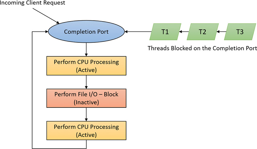
A server application will usually receive client requests via network endpoints that are identified by file handles. Examples include Windows Sockets 2 (Winsock2) sockets or named pipes. As the server creates its communications endpoints, it associates them with a completion port and its threads wait for incoming requests by calling GetQueuedCompletionStatus(Ex) on the port. When a thread is given a packet from the completion port, it will go off and start processing the request, becoming an active thread. A thread will block many times during its processing, such as when it needs to read or write data to a file on disk or when it synchronizes with other threads. Windows detects this activity and recognizes that the completion port has one less active thread. Therefore, when a thread becomes inactive because it blocks, a thread waiting on the completion port will be awakened if there is a packet in the queue.
Microsoft’s guidelines are to set the concurrency value roughly equal to the number of processors in a system. Keep in mind that it’s possible for the number of active threads for a completion port to exceed the concurrency limit. Consider a case in which the limit is specified as 1:
1. A client request comes in and a thread is dispatched to process the request, becoming active.
2. A second request arrives, but a second thread waiting on the port isn’t allowed to proceed because the concurrency limit has been reached.
3. The first thread blocks, waiting for a file I/O, so it becomes inactive.
4. The second thread is released.
5. While the second thread is still active, the first thread’s file I/O is completed, making it active again. At that point—and until one of the threads blocks—the concurrency value is 2, which is higher than the limit of 1. Most of the time, the count of active threads will remain at or just above the concurrency limit.
The completion port API also makes it possible for a server application to queue privately defined completion packets to a completion port by using the PostQueuedCompletionStatus function. A server typically uses this function to inform its threads of external events, such as the need to shut down gracefully.
Applications can use thread-agnostic I/O, described earlier, with I/O completion ports to avoid associating threads with their own I/Os and associating them with a completion port object instead. In addition to the other scalability benefits of I/O completion ports, their use can minimize context switches. Standard I/O completions must be executed by the thread that initiated the I/O, but when an I/O associated with an I/O completion port completes, the I/O manager uses any waiting thread to perform the completion operation.
I/O completion port operation
Windows applications create completion ports by calling the CreateIoCompletionPort Windows API and specifying a NULL completion port handle. This results in the execution of the NtCreateIoCompletion system service. The executive’s IoCompletion object contains a kernel synchronization object called a kernel queue. Thus, the system service creates a completion port object and initializes a queue object in the port’s allocated memory. (A pointer to the port also points to the queue object because the queue is the first member of the completion port.) A kernel queue object has a concurrency value that is specified when a thread initializes it, and in this case the value that is used is the one that was passed to CreateIoCompletionPort. KeInitializeQueue is the function that NtCreateIoCompletion calls to initialize a port’s queue object.
When an application calls CreateIoCompletionPort to associate a file handle with a port, the NtSetInformationFile system service is executed with the file handle as the primary parameter. The information class that is set is FileCompletionInformation, and the completion port’s handle and the CompletionKey parameter from CreateIoCompletionPort are the data values. NtSetInformationFile dereferences the file handle to obtain the file object and allocates a completion context data structure.
Finally, NtSetInformationFile sets the CompletionContext field in the file object to point at the context structure. When an asynchronous I/O operation completes on a file object, the I/O manager checks whether the CompletionContext field in the file object is non-NULL. If it is, the I/O manager allocates a completion packet and queues it to the completion port by calling KeInsertQueue with the port as the queue on which to insert the packet (this works because the completion port object and queue object have the same address).
When a server thread invokes GetQueuedCompletionStatus, the NtRemoveIoCompletion system service is executed. After validating parameters and translating the completion port handle to a pointer to the port, NtRemoveIoCompletion calls IoRemoveIoCompletion, which eventually calls KeRemoveQueueEx. For high-performance scenarios, it’s possible that multiple I/Os may have been completed, and although the thread will not block, it will still call into the kernel each time to get one item. The GetQueuedCompletionStatus or GetQueuedCompletionStatusEx API allows applications to retrieve more than one I/O completion status at the same time, reducing the number of user-to--kernel roundtrips and maintaining peak efficiency. Internally, this is implemented through the NtRemoveIoCompletionEx function. This calls IoRemoveIoCompletion with a count of queued items, which is passed on to KeRemoveQueueEx.
As you can see, KeRemoveQueueEx and KeInsertQueue are the engine behind completion ports. They are the functions that determine whether a thread waiting for an I/O completion packet should be activated. Internally, a queue object maintains a count of the current number of active threads and the maximum number of active threads. If the current number equals or exceeds the maximum when a thread calls KeRemoveQueueEx, the thread will be put (in LIFO order) onto a list of threads waiting for a turn to process a completion packet. The list of threads hangs off the queue object. A thread’s control block data structure (KTHREAD) has a pointer in it that references the queue object of a queue that it’s associated with; if the pointer is NULL, the thread isn’t associated with a queue.
Windows keeps track of threads that become inactive because they block on something other than the completion port by relying on the queue pointer in a thread’s control block. The scheduler routines that possibly result in a thread blocking (such as KeWaitForSingleObject, KeDelayExecutionThread, and so on) check the thread’s queue pointer. If the pointer isn’t NULL, the functions call KiActivate-WaiterQueue, a queue-related function that decrements the count of active threads associated with the queue. If the resulting number is less than the maximum and at least one completion packet is in the queue, the thread at the front of the queue’s thread list is awakened and given the oldest packet. Conversely, whenever a thread that is associated with a queue wakes up after blocking, the scheduler executes the KiUnwaitThread function, which increments the queue’s active count.
The PostQueuedCompletionStatus Windows API function results in the execution of the NtSet-IoCompletion system service. This function simply inserts the specified packet onto the completion port’s queue by using KeInsertQueue.
Figure 6-25 shows an example of a completion port object in operation. Even though two threads are ready to process completion packets, the concurrency value of 1 allows only one thread associated with the completion port to be active, and so the two threads are blocked on the completion port.

You can fine-tune the exact notification model of the I/O completion port through the SetFile-CompletionNotificationModes API, which allows application developers to take advantage of additional, specific improvements that usually require code changes but can offer even more throughput. Three notification-mode optimizations are supported, which are listed in Table 6-4. Note that these modes are per file handle and cannot be changed after being set.

I/O prioritization
Without I/O priority, background activities like search indexing, virus scanning, and disk defragmenting can severely impact the responsiveness of foreground operations. For example, a user who launches an application or opens a document while another process is performing disk I/O will experience delays as the foreground task waits for disk access. The same interference also affects the streaming playback of multimedia content like music from a disk.
Windows includes two types of I/O prioritization to help foreground I/O operations get preference: priority on individual I/O operations and I/O bandwidth reservations.
I/O priorities
The Windows I/O manager internally includes support for five I/O priorities, as shown in Table 6-5, but only three of the priorities are used. (Future versions of Windows may support High and Low.)
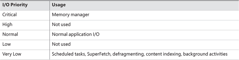
I/O has a default priority of Normal, and the memory manager uses Critical when it wants to write dirty memory data out to disk under low-memory situations to make room in RAM for other data and code. The Windows Task Scheduler sets the I/O priority for tasks that have the default task priority to Very Low. The priority specified by applications that perform background processing is Very Low. All the Windows background operations, including Windows Defender scanning and desktop search indexing, use Very Low I/O priority.
Prioritization strategies
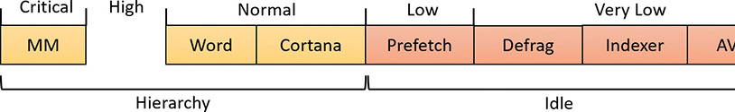
Internally, the five I/O priorities are divided into two I/O prioritization modes, called strategies. These are the hierarchy prioritization and the idle prioritization strategies. Hierarchy prioritization deals with all the I/O priorities except Very Low. It implements the following strategy:
![]() All critical-priority I/O must be processed before any high-priority I/O.
All critical-priority I/O must be processed before any high-priority I/O.
![]() All high-priority I/O must be processed before any normal-priority I/O.
All high-priority I/O must be processed before any normal-priority I/O.
![]() All normal-priority I/O must be processed before any low-priority I/O.
All normal-priority I/O must be processed before any low-priority I/O.
![]() All low-priority I/O is processed after any higher-priority I/O.
All low-priority I/O is processed after any higher-priority I/O.
As each application generates I/Os, IRPs are put on different I/O queues based on their priority, and the hierarchy strategy decides the ordering of the operations.
The idle prioritization strategy, on the other hand, uses a separate queue for non-idle priority I/O. Because the system processes all hierarchy prioritized I/O before idle I/O, it’s possible for the I/Os in this queue to be starved, as long as there’s even a single non-idle I/O on the system in the hierarchy priority strategy queue.
To avoid this situation, as well as to control back-off (the sending rate of I/O transfers), the idle strategy uses a timer to monitor the queue and guarantee that at least one I/O is processed per unit of time (typically, half a second). Data written using non-idle I/O priority also causes the cache manager to write modifications to disk immediately instead of doing it later and to bypass its read-ahead logic for read operations that would otherwise preemptively read from the file being accessed. The prioritization strategy also waits for 50 milliseconds after the completion of the last non-idle I/O in order to issue the next idle I/O. Otherwise, idle I/Os would occur in the middle of non-idle streams, causing costly seeks.
Combining these strategies into a virtual global I/O queue for demonstration purposes, a snapshot of this queue might look similar to Figure 6-26. Note that within each queue, the ordering is first-in, first-out (FIFO). The order in the figure is shown only as an example.
User-mode applications can set I/O priority on three different objects. The functions SetPriorityClass (with the PROCESS_MODE_BACKGROUND_BEGIN value) and SetThreadPriority (with the THREAD_MODE_BACKGROUND_BEGIN value), set the priority for all the I/Os that are generated by either the entire process or specific threads (the priority is stored in the IRP of each request). These functions work only on the current process or thread and lower the I/O priority to Very Low. In addition, these also lower the scheduling priority to 4 and the memory priority to 1. The function SetFileInformationByHandle can set the priority for a specific file object (the priority is stored in the file object). Drivers can also set I/O priority directly on an IRP by using the IoSetIoPriorityHint API.
The I/O priority field in the IRP and/or file object is a hint. There is no guarantee that the I/O priority will be respected or even supported by the different drivers that are part of the storage stack.
The two prioritization strategies are implemented by two different types of drivers. The hierarchy strategy is implemented by the storage port drivers, which are responsible for all I/Os on a specific port, such as ATA, SCSI, or USB. Only the ATA port driver (Ataport.sys) and USB port driver (Usbstor.sys) implement this strategy, while the SCSI and storage port drivers (Scsiport.sys and Storport.sys) do not.
![]() Note
Note
All port drivers check specifically for Critical priority I/Os and move them ahead of their queues, even if they do not support the full hierarchy mechanism. This mechanism is in place to support critical memory manager paging I/Os to ensure system reliability.
This means that consumer mass storage devices such as IDE or SATA hard drives and USB flash disks will take advantage of I/O prioritization, while devices based on SCSI, Fibre Channel, and iSCSI will not.
On the other hand, it is the system storage class device driver (Classpnp.sys) that enforces the idle strategy, so it automatically applies to I/Os directed at all storage devices, including SCSI drives. This separation ensures that idle I/Os will be subject to back-off algorithms to ensure a reliable system during operation under high idle I/O usage and so that applications that use them can make forward progress. Placing support for this strategy in the Microsoft-provided class driver avoids performance problems that would have been caused by lack of support for it in legacy third-party port drivers.
Figure 6-27 displays a simplified view of the storage stack that shows where each strategy is implemented. See Chapter 12 in Part 2 for more information on the storage stack.

I/O priority inversion avoidance
To avoid I/O priority inversion, in which a high I/O priority thread is starved by a low I/O priority thread, the executive resource (ERESOURCE) locking functionality uses several strategies. The ERESOURCE was picked for the implementation of I/O priority inheritance specifically because of its heavy use in file system and storage drivers, where most I/O priority inversion issues can appear. (See Chapter 8 in Part 2 for more on executive resources.)
If an ERESOURCE is being acquired by a thread with low I/O priority, and there are currently waiters on the ERESOURCE with normal or higher priority, the current thread is temporarily boosted to normal I/O priority by using the PsBoostThreadIo API, which increments the IoBoostCount in the ETHREAD structure. It also notifies Autoboost if the thread I/O priority was boosted or the boost was removed. (Refer to Chapter 4 for more on Autoboost.)
It then calls the IoBoostThreadIoPriority API, which enumerates all the IRPs queued to the target thread (recall that each thread has a list of pending IRPs) and checks which ones have a lower priority than the target priority (normal in this case), thus identifying pending idle I/O priority IRPs. In turn, the device object responsible for each of those IRPs is identified, and the I/O manager checks whether a priority callback has been registered, which driver developers can do through the IoRegisterPriority-Callback API and by setting the DO_PRIORITY_CALLBACK_ENABLED flag on their device object. Depending on whether the IRP was a paging I/O, this mechanism is called threaded boost or paging boost. Finally, if no matching IRPs were found, but the thread has at least some pending IRPs, all are boosted regardless of device object or priority, which is called blanket boosting.
I/O priority boosts and bumps
Windows uses a few other subtle modifications to normal I/O paths to avoid starvation, inversion, or otherwise unwanted scenarios when I/O priority is being used. Typically, these modifications are done by boosting I/O priority when needed. The following scenarios exhibit this behavior:
![]() When a driver is being called with an IRP targeted to a particular file object, Windows makes sure that if the request comes from kernel mode, the IRP uses normal priority even if the file object has a lower I/O priority hint. This is called a kernel bump.
When a driver is being called with an IRP targeted to a particular file object, Windows makes sure that if the request comes from kernel mode, the IRP uses normal priority even if the file object has a lower I/O priority hint. This is called a kernel bump.
![]() When reads or writes to the paging file are occurring (through
When reads or writes to the paging file are occurring (through IoPageRead and IoPageWrite), Windows checks whether the request comes from kernel mode and is not being performed on behalf of Superfetch (which always uses idle I/O). In this case, the IRP uses normal priority even if the current thread has a lower I/O priority. This is called a paging bump.
The following experiment will show you an example of Very Low I/O priority and how you can use Process Monitor to look at I/O priorities on different requests.
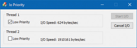
EXPERIMENT: Very low versus normal I/O throughput
2. In the dialog box, under Thread 1, check the Low Priority check box.
3. Click the Start I/O button. You should notice a significant difference in speed between the two threads, as shown in the following screenshot:
![]() Note
Note
If both threads run at low priority and the system is relatively idle, their throughput will be roughly equal to the throughput of a single normal I/O priority in the example. This is because low-priority I/Os are not artificially throttled or otherwise hindered if there isn’t any competition from higher-priority I/O.
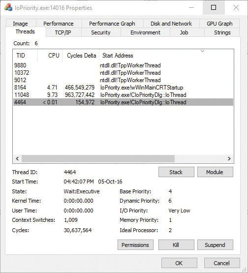
4. Open the process in Process Explorer and look at the low I/O priority thread to see the priorities:
5. You can also use Process Monitor to trace IO Priority’s I/Os and look at their I/O priority hint. To do so, launch Process Monitor, configure a filter for IoPriority.exe, and repeat the experiment. In this application, each thread reads from a file named _File_ concatenated with the thread ID.
6. Scroll down until you see a write to File_1. You should see output similar to the following:
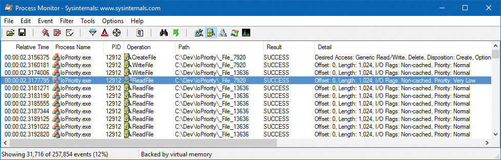
7. Notice that I/Os directed at _File_7920 in the screenshot have a priority of very low. Looking at the Time of Day and Relative Time columns, you’ll also notice that the I/Os are spaced half a second from each other, which is another sign of the idle strategy in action.
EXPERIMENT: Performance analysis of I/O priority boosting/bumping
![]()
IoLowPriorityReadOperationCount and IoLowPriorityWriteOperationCount
![]()
IoKernelIssuedIoBoostedCount
![]()
IoPagingReadLowPriorityCount and IoPagingWriteLowPriorityCount
![]()
IoPagingReadLowPriorityBumpedCount and IoPagingWriteLowPriorityBumpedCount
![]()
IoBoostedThreadedIrpCount and IoBoostedPagingIrpCount
![]()
IoBlanketBoostCount
Bandwidth reservation (scheduled file I/O)
Windows I/O bandwidth-reservation support is useful for applications that desire consistent I/O throughput. For example, using the SetFileBandwidthReservation call, a media player application can ask the I/O system to guarantee it the ability to read data from a device at a specified rate. If the device can deliver data at the requested rate and existing reservations allow it, the I/O system gives the application guidance as to how fast it should issue I/Os and how large the I/Os should be.
The I/O system won’t service other I/Os unless it can satisfy the requirements of applications that have made reservations on the target storage device. Figure 6-28 shows a conceptual timeline of I/Os issued on the same file. The shaded regions are the only ones that will be available to other applications. If I/O bandwidth is already taken, new I/Os will have to wait until the next cycle.

Like the hierarchy prioritization strategy, bandwidth reservation is implemented at the port driver level, which means it is available only for IDE, SATA, or USB-based mass-storage devices.
Container notifications
Container notifications are specific classes of events that drivers can register for through an asynchronous callback mechanism by using the IoRegisterContainerNotification API and selecting the notification class that interests them. Thus far, one such class is implemented in Windows: IoSessionStateNotification. This class allows drivers to have their registered callback invoked whenever a change in the state of a given session is registered. The following changes are supported:
![]() A session is created or terminated.
A session is created or terminated.
![]() A user connects to or disconnects from a session.
A user connects to or disconnects from a session.
![]() A user logs on to or logs off from a session.
A user logs on to or logs off from a session.
By specifying a device object that belongs to a specific session, the driver callback will be active only for that session. In contrast, by specifying a global device object (or no device object at all), the driver will receive notifications for all events on a system. This feature is particularly useful for devices that participate in the Plug and Play device redirection functionality that is provided through Terminal Services, which allows a remote device to be visible on the connecting host’s Plug and Play manager bus as well (such as audio or printer device redirection). Once the user disconnects from a session with audio playback, for example, the device driver needs a notification in order to stop redirecting the source audio stream.
Driver Verifier
Driver Verifier is a mechanism that can be used to help find and isolate common bugs in device drivers or other kernel-mode system code. Microsoft uses Driver Verifier to check its own device drivers as well as all device drivers that vendors submit for WHQL testing. Doing so ensures that the drivers submitted are compatible with Windows and free from common driver errors. (Although not described in this book, there is also a corresponding Application Verifier tool that has resulted in quality improvements for user-mode code in Windows.)
Although Driver Verifier serves primarily as a tool to help device driver developers discover bugs in their code, it is also a powerful tool for system administrators experiencing crashes. Chapter 15 in Part 2 describes its role in crash analysis troubleshooting.
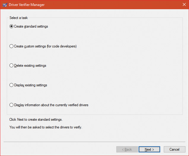
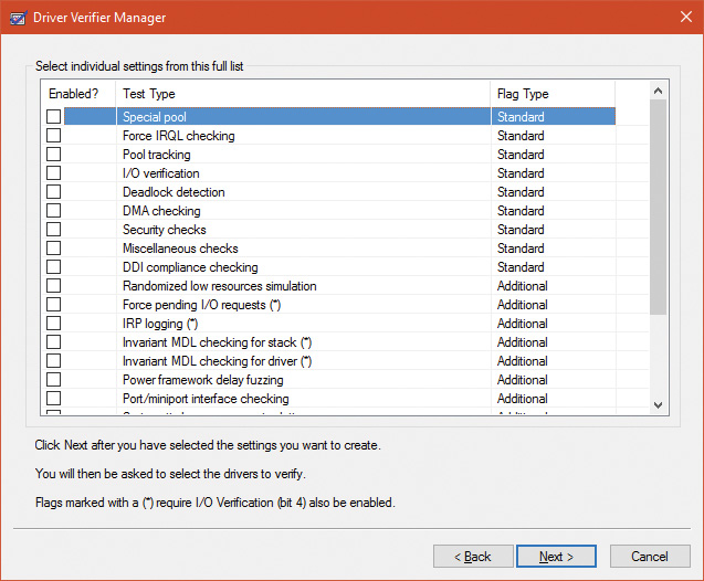
Driver Verifier consists of support in several system components: the memory manager, I/O manager, and HAL all have driver verification options that can be enabled. These options are configured using the Driver Verifier Manager (%SystemRoot%System32Verifier.exe). When you run Driver Verifier with no command-line arguments, it presents a wizard-style interface, as shown in Figure 6-29. (You can also enable and disable Driver Verifier, as well as display current settings, by using its command-line interface. From a command prompt, type verifier /? to see the switches.)
Driver Verifier Manager distinguishes between two sets of settings: standard and additional. This is somewhat arbitrary, but the standard settings represent the more common options that should be probably selected for every driver being tested, while the additional settings represent those settings that are less common or specific to some types of drivers. Selecting Create Custom Settings from the main wizard’s page shows all options with a column indicating which is standard and which is additional, as shown in Figure 6-30.
Regardless of which options are selected, Driver Verifier always monitors drivers selected for verification, looking for a number of illegal and boundary operations, including calling kernel-memory pool functions at invalid IRQL, double-freeing memory, releasing spinlocks inappropriately, not freeing timers, referencing a freed object, delaying shutdown for longer than 20 minutes, and requesting a zero-size memory allocation.
Driver Verifier settings are stored in the registry under the HKLMSYSTEMCurrentControlSetControlSession ManagerMemory Management key. The VerifyDriverLevel value contains a bitmask that represents the verification options that are enabled. The VerifyDrivers value contains the names of the drivers to monitor. (These values won’t exist in the registry until you select drivers to verify in the Driver Verifier Manager.) If you choose to verify all drivers (which you should never do, since this will cause considerable system slowdown), VerifyDrivers is set to an asterisk (*) character. Depending on the settings you have made, you might need to reboot the system for the selected verification to occur.
Early in the boot process, the memory manager reads the Driver Verifier registry values to determine which drivers to verify and which Driver Verifier options you enabled. (Note that if you boot in safe mode, any Driver Verifier settings are ignored.) Subsequently, if you’ve selected at least one driver for verification, the kernel checks the name of every device driver it loads into memory against the list of drivers you’ve selected for verification. For every device driver that appears in both places, the kernel invokes the VfLoadDriver function, which calls other internal Vf* functions to replace the driver’s references to a number of kernel functions with references to Driver Verifier–equivalent versions of those functions. For example, ExAllocatePool is replaced with a call to VerifierAllocatePool. The windowing system driver (Win32k.sys) also makes similar changes to use Driver Verifier–equivalent functions.
I/O-related verification options
The various I/O-related verification options are as follows:
![]() I/O Verification When this option is selected, the I/O manager allocates IRPs for verified drivers from a special pool and their usage is tracked. In addition, the Driver Verifier crashes the system when an IRP is completed that contains an invalid status or when an invalid device object is passed to the I/O manager. This option also monitors all IRPs to ensure that drivers mark them correctly when completing them asynchronously, that they manage device-stack locations correctly, and that they delete device objects only once. In addition, the Verifier randomly stresses drivers by sending them fake power management and WMI IRPs, changing the order in which devices are enumerated, and adjusting the status of PnP and power IRPs when they complete to test for drivers that return incorrect status from their dispatch routines. Finally, the Verifier also detects incorrect re-initialization of remove locks while they are still being held due to pending device removal.
I/O Verification When this option is selected, the I/O manager allocates IRPs for verified drivers from a special pool and their usage is tracked. In addition, the Driver Verifier crashes the system when an IRP is completed that contains an invalid status or when an invalid device object is passed to the I/O manager. This option also monitors all IRPs to ensure that drivers mark them correctly when completing them asynchronously, that they manage device-stack locations correctly, and that they delete device objects only once. In addition, the Verifier randomly stresses drivers by sending them fake power management and WMI IRPs, changing the order in which devices are enumerated, and adjusting the status of PnP and power IRPs when they complete to test for drivers that return incorrect status from their dispatch routines. Finally, the Verifier also detects incorrect re-initialization of remove locks while they are still being held due to pending device removal.
![]() DMA Checking DMA is a hardware-supported mechanism that allows devices to transfer data to or from physical memory without involving the CPU. The I/O manager provides several functions that drivers use to initiate and control DMA operations, and this option enables checks for the correct use of the functions and buffers that the I/O manager supplies for DMA operations.
DMA Checking DMA is a hardware-supported mechanism that allows devices to transfer data to or from physical memory without involving the CPU. The I/O manager provides several functions that drivers use to initiate and control DMA operations, and this option enables checks for the correct use of the functions and buffers that the I/O manager supplies for DMA operations.
![]() Force Pending I/O Requests For many devices, asynchronous I/Os complete immediately, so drivers may not be coded to properly handle the occasional asynchronous I/O. When this option is enabled, the I/O manager randomly returns
Force Pending I/O Requests For many devices, asynchronous I/Os complete immediately, so drivers may not be coded to properly handle the occasional asynchronous I/O. When this option is enabled, the I/O manager randomly returns STATUS_PENDING in response to a driver’s calls to IoCallDriver, which simulates the asynchronous completion of an I/O.
![]() IRP Logging This option monitors a driver’s use of IRPs and makes a record of IRP usage, which is stored as WMI information. You can then use the Dc2wmiparser.exe utility in the WDK to convert these WMI records to a text file. Note that only 20 IRPs for each device will be recorded—each subsequent IRP will overwrite the least recently added entry. After a reboot, this information is discarded, so Dc2wmiparser.exe should be run if the contents of the trace are to be analyzed later.
IRP Logging This option monitors a driver’s use of IRPs and makes a record of IRP usage, which is stored as WMI information. You can then use the Dc2wmiparser.exe utility in the WDK to convert these WMI records to a text file. Note that only 20 IRPs for each device will be recorded—each subsequent IRP will overwrite the least recently added entry. After a reboot, this information is discarded, so Dc2wmiparser.exe should be run if the contents of the trace are to be analyzed later.
Memory-related verification options
The following are memory-related verification options supported by Driver Verifier. (Some are also related to I/O operations.)
Special Pool
Selecting the Special Pool option causes the pool allocation routines to bracket pool allocations with an invalid page so that references before or after the allocation will result in a kernel-mode access violation, thus crashing the system with the finger pointed at the buggy driver. Special pool also causes some additional validation checks to be performed when a driver allocates or frees memory. With special pool enabled, the pool allocation routines allocate a region of kernel memory for Driver Verifier to use. Driver Verifier redirects memory allocation requests that drivers under verification make to the special pool area rather than to the standard kernel-mode memory pools. When a device driver allocates memory from special pool, Driver Verifier rounds up the allocation to an even-page boundary. Because Driver Verifier brackets the allocated page with invalid pages, if a device driver attempts to read or write past the end of the buffer, the driver will access an invalid page, and the memory manager will raise a kernel-mode access violation.
Figure 6-31 shows an example of the special pool buffer that Driver Verifier allocates to a device driver when Driver Verifier checks for overrun errors.

By default, Driver Verifier performs overrun detection. It does this by placing the buffer that the device driver uses at the end of the allocated page and filling the beginning of the page with a random pattern. Although the Driver Verifier Manager doesn’t let you specify underrun detection, you can set this type of detection manually by adding the DWORD registry value PoolTagOverruns to the HKLMSYSTEMCurrentControlSetControlSession ManagerMemory Management key and setting it to 0 (or by running the Gflags.exe utility and selecting the Verify Start option in the Kernel Special Pool Tag section instead of the default option, Verify End). When Windows enforces underrun detection, Driver Verifier allocates the driver’s buffer at the beginning of the page rather than at the end.
The overrun-detection configuration includes some measure of underrun detection as well. When the driver frees its buffer to return the memory to Driver Verifier, Driver Verifier ensures that the pattern preceding the buffer hasn’t changed. If the pattern is modified, the device driver has underrun the buffer and written to memory outside the buffer.
Special pool allocations also check to ensure that the processor IRQL at the time of an allocation and deallocation is legal. This check catches an error that some device drivers make: allocating pageable memory from an IRQL at DPC/dispatch level or above.
You can also configure special pool manually by adding the DWORD registry value PoolTag in the HKLMSYSTEMCurrentControlSetControlSession ManagerMemory Management key, which represents the allocation tags the system uses for special pool. Thus, even if Driver Verifier isn’t configured to verify a particular device driver, if the tag the driver associates with the memory it allocates matches what is specified in the PoolTag registry value, the pool allocation routines will allocate the memory from special pool. If you set the value of PoolTag to 0x2a or to the wildcard (*), all memory that drivers allocate will be from special pool, provided there’s enough virtual and physical memory (drivers will revert to allocating from regular pool if there aren’t enough free pages).
Pool tracking
If pool tracking is enabled, the memory manager checks at driver unload time whether the driver freed all the memory allocations it made. If it didn’t, it crashes the system, indicating the buggy driver. Driver Verifier also shows general pool statistics on the Driver Verifier Manager’s Pool Tracking tab (accessible from the main wizard UI by selecting Display Information About the Currently Verified Drivers and selecting Next twice). You can also use the !verifier kernel debugger command. This command shows more information than Driver Verifier and is useful to driver writers.
Pool tracking and special pool cover not only explicit allocation calls, such as ExAllocatePoolWithTag, but also calls to other kernel APIs that implicitly allocate memory from pools: IoAllocateMdl, IoAllocateIrp, and other IRP allocation calls; various Rtl string APIs; and IoSetCompletionRoutineEx.
Another driver verified function enabled by the Pool Tracking option pertains to pool quota charges. The call to ExAllocatePoolWithQuotaTag charges the current process’s pool quota for the number of bytes allocated. If such a call is made from a DPC routine, the process that is charged is unpredictable because DPC routines may execute in the context of any process. The Pool Tracking option checks for calls to this routine from the DPC routine context.
Driver Verifier can also perform locked memory page tracking, which additionally checks for pages that have been left locked after an I/O operation completes and generates a DRIVER_LEFT_LOCKED_PAGES_IN_PROCESS crash code instead of PROCESS_HAS_LOCKED_PAGES—the former indicates the driver responsible for the error as well as the function responsible for the locking of the pages.
Force IRQL Checking
One of the most common device driver bugs occurs when a driver accesses pageable data or code when the processor on which the device driver is executing is at an elevated IRQL. The memory manager can’t service a page fault when the IRQL is DPC/dispatch level or above. The system often doesn’t detect instances of a device driver accessing pageable data when the processor is executing at a high IRQL level because the pageable data being accessed happens to be physically resident at the time. At other times, however, the data might be paged out, which results in a system crash with the stop code IRQL_NOT_LESS_OR_EQUAL (that is, the IRQL wasn’t less than or equal to the level required for the operation attempted—in this case, accessing pageable memory).
Although testing device drivers for this kind of bug is usually difficult, Driver Verifier makes it easy. If you select the Force IRQL Checking option, Driver Verifier forces all kernel-mode pageable code and data out of the system working set whenever a device driver under verification raises the IRQL. The internal function that does this is MiTrimAllSystemPagableMemory. With this setting enabled, whenever a device driver under verification accesses pageable memory when the IRQL is elevated, the system instantly detects the violation, and the resulting system crash identifies the faulty driver.
Another common driver crash that results from incorrect IRQL usage occurs when synchronization objects are part of data structures that are paged and then waited on. Synchronization objects should never be paged because the dispatcher needs to access them at an elevated IRQL, which would cause a crash. Driver Verifier checks whether any of the following structures are present in pageable memory: KTIMER, KMUTEX, KSPIN_LOCK, KEVENT, KSEMAPHORE, ERESOURCE, and FAST_MUTEX.
Low Resources Simulation
Enabling Low Resources Simulation causes Driver Verifier to randomly fail memory allocations that verified device drivers perform. In the past, developers wrote many device drivers under the assumption that kernel memory would always be available, and that if memory ran out, the device driver didn’t have to worry about it because the system would crash anyway. However, because low-memory conditions can occur temporarily, and today’s mobile devices are not as powerful as larger machines, it’s important that device drivers properly handle allocation failures that indicate kernel memory is exhausted.
The driver calls that will be injected with random failures include the functions ExAllocatePool*, MmProbeAndLockPages, MmMapLockedPagesSpecifyCache, MmMapIoSpace, MmAllocateContiguous-Memory, MmAllocatePagesForMdl, IoAllocateIrp, IoAllocateMdl, IoAllocateWorkItem, IoAllocateErrorLogEntry, IOSetCompletionRoutineEx, and various Rtl string APIs that allocate from the pool. Driver Verifier also fails some allocations made by kernel GDI functions (see the WDK documentation for a complete list). Additionally, you can specify the following:
![]() The probability that allocation will fail This is 6 percent by default.
The probability that allocation will fail This is 6 percent by default.
![]() Which applications should be subject to the simulation All are by default.
Which applications should be subject to the simulation All are by default.
![]() Which pool tags should be affected All are by default.
Which pool tags should be affected All are by default.
![]() What delay should be used before fault injection starts The default is 7 minutes after the system boots, which is enough time to get past the critical initialization period in which a low-memory condition might prevent a device driver from loading.
What delay should be used before fault injection starts The default is 7 minutes after the system boots, which is enough time to get past the critical initialization period in which a low-memory condition might prevent a device driver from loading.
You can change these customizations with command line options to verifier.exe.
After the delay period, Driver Verifier starts randomly failing allocation calls for device drivers it is verifying. If a driver doesn’t correctly handle allocation failures, this will likely show up as a system crash.
Systematic Low Resources Simulation
Similar to the Low Resources Simulation option, this option fails certain calls to the kernel and Ndis.Sys (for network drivers), but does so in a systematic way, by examining the call stack at the point of failure injection. If the driver handles the failure correctly, that call stack will not be failure injected again. This allows the driver writer to see issues in a systematic way, fix a reported issue, and then move on to the next. Examining call stacks is a relatively expensive operation, therefore verifying more than a single driver at a time with this setting is not recommended.
Miscellaneous checks
Some of the checks that Driver Verifier calls miscellaneous allow it to detect the freeing of certain system structures in the pool that are still active. For example, Driver Verifier will check for:
![]() Active work items in freed memory A driver calls
Active work items in freed memory A driver calls ExFreePool to free a pool block in which one or more work items queued with IoQueueWorkItem are present.
![]() Active resources in freed memory A driver calls
Active resources in freed memory A driver calls ExFreePool before calling ExDelete-Resource to destroy an ERESOURCE object.
![]() Active look-aside lists in freed memory A driver calls
Active look-aside lists in freed memory A driver calls ExFreePool before calling ExDelete- NPagedLookasideList or ExDeletePagedLookasideList to delete the look-aside list.
Finally, when verification is enabled, Driver Verifier performs certain automatic checks that cannot be individually enabled or disabled. These include the following:
![]() Calling
Calling MmProbeAndLockPages or MmProbeAndLockProcessPages on an MDL having incorrect flags. For example, it is incorrect to call MmProbeAndLockPages for an MDL that was set up by calling MmBuildMdlForNonPagedPool.
![]() Calling
Calling MmMapLockedPages on an MDL having incorrect flags. For example, it is incorrect to call MmMapLockedPages for an MDL that is already mapped to a system address. Another example of incorrect driver behavior is calling MmMapLockedPages for an MDL that was not locked.
![]() Calling
Calling MmUnlockPages or MmUnmapLockedPages on a partial MDL (created by using IoBuildPartialMdl).
![]() Calling
Calling MmUnmapLockedPages on an MDL that is not mapped to a system address.
![]() Allocating synchronization objects such as events or mutexes from
Allocating synchronization objects such as events or mutexes from NonPagedPoolSession memory.
Driver Verifier is a valuable addition to the arsenal of verification and debugging tools available to device driver writers. Many device drivers that first ran with Driver Verifier had bugs that Driver Verifier was able to expose. Thus, Driver Verifier has resulted in an overall improvement in the quality of all kernel-mode code running in Windows.
The Plug and Play manager
The PnP manager is the primary component involved in supporting the ability of Windows to recognize and adapt to changing hardware configurations. A user doesn’t need to understand the intricacies of hardware or manual configuration to install and remove devices. For example, it’s the PnP manager that enables a running Windows laptop that is placed on a docking station to automatically detect additional devices located in the docking station and make them available to the user.
Plug and Play support requires cooperation at the hardware, device driver, and operating system levels. Industry standards for the enumeration and identification of devices attached to buses are the foundation of Windows Plug and Play support. For example, the USB standard defines the way that devices on a USB bus identify themselves. With this foundation in place, Windows Plug and Play support provides the following capabilities:
![]() The PnP manager automatically recognizes installed devices, a process that includes enumerating devices attached to the system during a boot and detecting the addition and removal of devices as the system executes.
The PnP manager automatically recognizes installed devices, a process that includes enumerating devices attached to the system during a boot and detecting the addition and removal of devices as the system executes.
![]() Hardware resource allocation is a role the PnP manager fills by gathering the hardware resource requirements (interrupts, I/O memory, I/O registers, or bus-specific resources) of the devices attached to a system and, in a process called resource arbitration, optimally assigning resources so that each device meets the requirements necessary for its operation. Because hardware devices can be added to the system after boot-time resource assignment, the PnP manager must also be able to reassign resources to accommodate the needs of dynamically added devices.
Hardware resource allocation is a role the PnP manager fills by gathering the hardware resource requirements (interrupts, I/O memory, I/O registers, or bus-specific resources) of the devices attached to a system and, in a process called resource arbitration, optimally assigning resources so that each device meets the requirements necessary for its operation. Because hardware devices can be added to the system after boot-time resource assignment, the PnP manager must also be able to reassign resources to accommodate the needs of dynamically added devices.
![]() Loading appropriate drivers is another responsibility of the PnP manager. The PnP manager determines, based on the identification of a device, whether a driver capable of managing the device is installed on the system, and if one is, it instructs the I/O manager to load it. If a suitable driver isn’t installed, the kernel-mode PnP manager communicates with the user-mode PnP manager to install the device, possibly requesting the user’s assistance in locating a suitable driver.
Loading appropriate drivers is another responsibility of the PnP manager. The PnP manager determines, based on the identification of a device, whether a driver capable of managing the device is installed on the system, and if one is, it instructs the I/O manager to load it. If a suitable driver isn’t installed, the kernel-mode PnP manager communicates with the user-mode PnP manager to install the device, possibly requesting the user’s assistance in locating a suitable driver.
![]() The PnP manager also implements application and driver mechanisms for the detection of hardware configuration changes. Applications or drivers sometimes require a specific hardware device to function, so Windows includes a means for them to request notification of the presence, addition, or removal of devices.
The PnP manager also implements application and driver mechanisms for the detection of hardware configuration changes. Applications or drivers sometimes require a specific hardware device to function, so Windows includes a means for them to request notification of the presence, addition, or removal of devices.
![]() It provides a place for storing device state, and it participates in system setup, upgrade, migration, and offline image management.
It provides a place for storing device state, and it participates in system setup, upgrade, migration, and offline image management.
![]() It supports network connected devices, such as network projectors and printers, by allowing specialized bus drivers to detect the network as a bus and create device nodes for the devices running on it.
It supports network connected devices, such as network projectors and printers, by allowing specialized bus drivers to detect the network as a bus and create device nodes for the devices running on it.
Level of Plug and Play support
Windows aims to provide full support for Plug and Play, but the level of support possible depends on the attached devices and installed drivers. If a single device or driver doesn’t support Plug and Play, the extent of Plug and Play support for the system can be compromised. In addition, a driver that doesn’t support Plug and Play might prevent other devices from being usable by the system. Table 6-6 shows the outcome of various combinations of devices and drivers that can and can’t support Plug and Play.

A device that isn’t Plug and Play–compatible is one that doesn’t support automatic detection, such as a legacy ISA sound card. Because the operating system doesn’t know where the hardware physically lies, certain operations—such as laptop undocking, sleep, and hibernation—are disallowed. However, if a Plug and Play driver is manually installed for the device, the driver can at least implement PnP manager–directed resource assignment for the device.
Drivers that aren’t Plug and Play–compatible include legacy drivers, such as those that ran on Windows NT 4. Although these drivers might continue to function on later versions of Windows, the PnP manager can’t reconfigure the resources assigned to such devices in the event that resource reallocation is necessary to accommodate the needs of a dynamically added device. For example, a device might be able to use I/O memory ranges A and B, and during the boot, the PnP manager assigns it range A. If a device that can use only A is attached to the system later, the PnP manager can’t direct the first device’s driver to reconfigure itself to use range B. This prevents the second device from obtaining required resources, which results in the device being unavailable for use by the system. Legacy drivers also impair a machine’s ability to sleep or hibernate. (See the section “The power manager” later in this chapter for more details.)
Device enumeration
Device enumeration occurs when the system boots, resumes from hibernation, or is explicitly instructed to do so (for example, by clicking Scan for Hardware Changes in the Device Manager UI). The PnP manager builds a device tree (described momentarily) and compares it to its known stored tree from a previous enumeration, if any. For a boot or resume from hibernation, the stored device tree is empty. Newly discovered devices and removed devices require special treatment, such as loading appropriate drivers (for a newly discovered device) and notifying drivers of a removed device.
The PnP manager begins device enumeration with a virtual bus driver called Root, which represents the entire computer system and acts as the bus driver for non–Plug and Play drivers and the HAL. The HAL acts as a bus driver that enumerates devices directly attached to the motherboard as well as system components such as batteries. Instead of actually enumerating, however, the HAL relies on the hardware description the Setup process recorded in the registry to detect the primary bus (in most cases, a PCI bus) and devices such as batteries and fans.
The primary bus driver enumerates the devices on its bus, possibly finding other buses, for which the PnP manager initializes drivers. Those drivers in turn can detect other devices, including other subsidiary buses. This recursive process of enumeration, driver loading (if the driver isn’t already loaded), and further enumeration proceeds until all the devices on the system have been detected and configured.
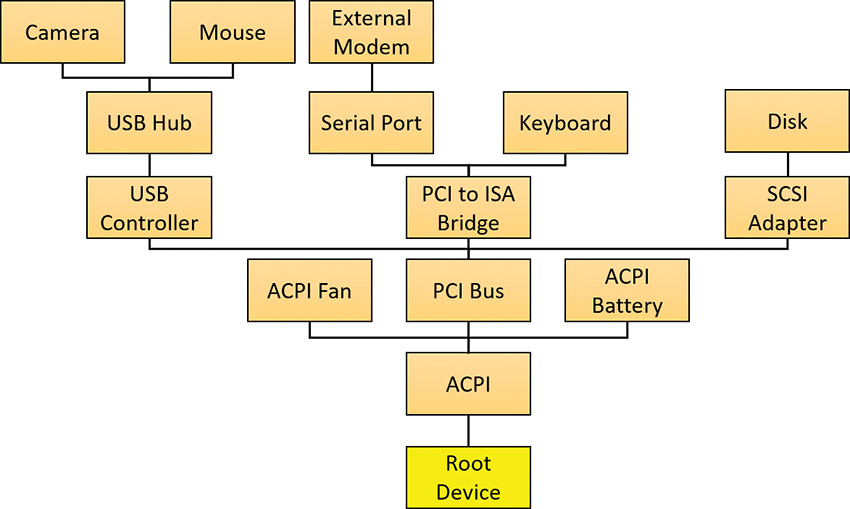
As the bus drivers report detected devices to the PnP manager, the PnP manager creates an internal tree called a device tree that represents the relationships between devices. Nodes in the tree are called device nodes, or devnodes. A devnode contains information about the device objects that represent the device as well as other Plug and Play–related information stored in the devnode by the PnP manager. Figure 6-32 shows an example of a simplified device tree. A PCI bus serves as the system’s primary bus, which USB, ISA, and SCSI buses are connected to.
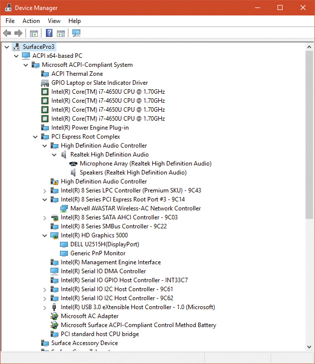
The Device Manager utility, which is accessible from the Computer Management snap-in in the Programs/Administrative Tools folder of the Start menu (and also from the Device Manager link of the System utility in Control Panel), shows a simple list of devices present on a system in its default configuration. You can also select the Devices by Connection option from the Device Manager’s View menu to see the devices as they relate to the device tree. Figure 6-33 shows an example of the Device Manager’s Devices by connection view.
Device stacks
As devnodes are created by the PnP manager, driver objects and device objects are created to manage and logically represent the linkage between the devices that make up the devnode. This linkage is called a device stack (briefly discussed in the “IRP flow” section earlier in this chapter). You can think of the device stack as an ordered list of device object/driver pairs. Each device stack is built from the bottom to the top. Figure 6-34 shows an example of a devnode (a reprint of Figure 6-6), with seven device objects (all managing the same physical device). Each devnode contains at least two devices (PDO and FDO), but can contain more device objects. A device stack consists of the following:

![]() A physical device object (PDO) that the PnP manager instructs a bus driver to create when the bus driver reports the presence of a device on its bus during enumeration. The PDO represents the physical interface to the device and is always at the bottom of the device stack.
A physical device object (PDO) that the PnP manager instructs a bus driver to create when the bus driver reports the presence of a device on its bus during enumeration. The PDO represents the physical interface to the device and is always at the bottom of the device stack.
![]() One or more optional filter device objects (FiDOs) that layer between the PDO and the functional device object (FDO; described in the next bullet), called lower filters (the term “lower” is always considered in relation to the FDO). These may be used for intercepting IRPs coming out of the FDO and towards the bus driver (which may be of interest to bus filters).
One or more optional filter device objects (FiDOs) that layer between the PDO and the functional device object (FDO; described in the next bullet), called lower filters (the term “lower” is always considered in relation to the FDO). These may be used for intercepting IRPs coming out of the FDO and towards the bus driver (which may be of interest to bus filters).
![]() One (and only one) functional device object (FDO) that is created by the driver, which is called a function driver, that the PnP manager loads to manage a detected device. An FDO represents the logical interface to a device, having the most “intimate” knowledge of the functionality provided by the device. A function driver can also act as a bus driver if devices are attached to the device represented by the FDO. The function driver often creates an interface (essentially a name) to the FDO’s corresponding PDO so that applications and other drivers can open the device and interact with it. Sometimes function drivers are divided into a separate class/port driver and miniport driver that work together to manage I/O for the FDO.
One (and only one) functional device object (FDO) that is created by the driver, which is called a function driver, that the PnP manager loads to manage a detected device. An FDO represents the logical interface to a device, having the most “intimate” knowledge of the functionality provided by the device. A function driver can also act as a bus driver if devices are attached to the device represented by the FDO. The function driver often creates an interface (essentially a name) to the FDO’s corresponding PDO so that applications and other drivers can open the device and interact with it. Sometimes function drivers are divided into a separate class/port driver and miniport driver that work together to manage I/O for the FDO.
![]() One or more optional FiDOs that layer above the FDO, called upper filters. These get first crack at an IRP header for the FDO.
One or more optional FiDOs that layer above the FDO, called upper filters. These get first crack at an IRP header for the FDO.
![]() Note
Note
The various device objects have different names in Figure 6-34 to make them easier to describe. However, they are all instances of DEVICE_OBJECT structures.
Device stacks are built from the bottom up and rely on the I/O manager’s layering functionality, so IRPs flow from the top of a device stack toward the bottom. However, any level in the device stack can choose to complete an IRP, as described in the “IRP flow” section earlier in this chapter.
Device-stack driver loading
How does the PnP manager find the correct drivers as part of building the device stack? The registry has this information scattered in three important keys (and their subkeys), shown in Table 6-7. (Note that CCS is short for CurrentControlSet.)

When a bus driver performs device enumeration and discovers a new device, it first creates a PDO to represent the existence of the physical device that has been detected. Next, it informs the PnP manager by calling IoInvalidateDeviceRelations (documented in the WDK) with the BusRelations enumeration value and the PDO, indicating to the PnP manager that a change on its bus has been detected. In response, the PnP manager asks the bus driver (through an IRP) for the device identifier.
The identifiers are bus-specific; for example, a USB device identifier consists of a vendor ID (VID) for the hardware vendor that made the device and a product ID (PID) that the vendor assigned to the device. For a PCI device, a similar vendor ID is required, along with a device ID, to uniquely identify the device within a vendor (plus some optional components; see the WDK for more information on device ID formats). Together, these IDs form what Plug and Play calls a device ID. The PnP manager also queries the bus driver for an instance ID to help it distinguish different instances of the same hardware. The instance ID can describe either a bus-relative location (for example, the USB port) or a globally unique descriptor (for example, a serial number).
The device ID and instance ID are combined to form a device instance ID (DIID), which the PnP manager uses to locate the device’s key under the Hardware key shown in Table 6-7. The subkeys under that key have the form <Enumerator><Device ID><Instance ID>, where the enumerator is a bus driver, the device ID is a unique identifier for a type of device, and the instance ID uniquely identifies different instances of the same hardware.
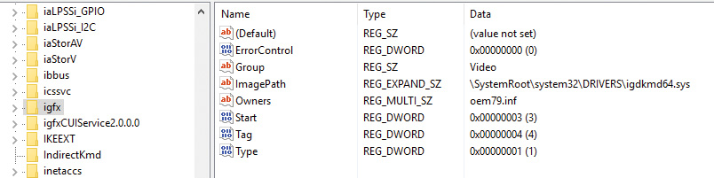
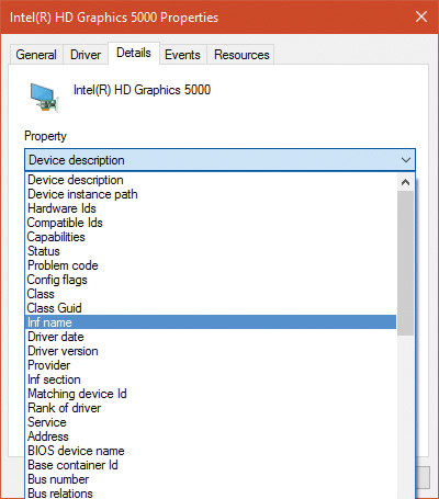
Figure 6-35 presents an example of an enumeration subkey of an Intel display card. The device’s key contains descriptive data and includes values named Service and ClassGUID (which are obtained from a driver’s INF file upon installation) that help the PnP manager locate the device’s drivers as follows:
![]() The
The Service value is looked up in the Software key, and there the path to the driver (SYS file) is stored in the ImagePath value. Figure 6-36 shows the Software subkey named igfx (from Figure 6-35) where the Intel display driver can be located. The PnP manager will load that driver (if it’s not already loaded), call its add-device routine, and there the driver will create the FDO.
![]() If a value named
If a value named LowerFilters is present, it contains a multiple string list of drivers to load as lower filters, which can be located in the Software subkey. The PnP manager loads these drivers before loading the driver associated with the Service value above.

![]() If a value named
If a value named UpperFilters is present, it indicates a list of driver names (under the Software key, similar to LowerFilters) which the PnP manager will load in much the same way after it loads the driver pointed to by the Service value.
![]() The
The ClassGUID value represents the general type of device (display, keyboard, disk, etc.), and points to a subkey under the Class key (from Table 6-7). The key represents settings applicable to all drivers for that type of device. In particular, if the values LowerFilters and/or UpperFilters are present, they are treated just like the same values in the Hardware key of the particular device. This allows, for example, the loading of an upper filter for keyboard devices, regardless of the particular keyboard or the vendor. Figure 6-37 shows the class key for keyboard devices. Notice the friendly name (Keyboard), although the GUID is what matters (the decision on the particular class is provided as part of the installation INF file). An UpperFilters value exists, listing the system provided keyboard class driver that always loads as part of any keyboard devnode. (You can also see the IconPath value that is used as the icon for the keyboard type in the Device Manager’s UI.)

To summarize, the order of driver loading for a devnode is as follows:
1. The bus driver is loaded, creating the PDO.
2. Any lower filters listed in the Hardware instance key are loaded, in the order listed (multi string), creating their filter device objects (FiDOs in Figure 6-34).
3. Any lower filters listed in the corresponding Class key are loaded in the order listed, creating their FiDOs.
4. The driver listed in the Service value is loaded, creating the FDO.
5. Any upper filters listed in the Hardware instance key are loaded, in the order listed, creating their FiDOs.
6. Any upper filters listed in the corresponding Class key are loaded in the order listed creating their FiDOs.
To deal with multifunction devices (such as all-in-one printers or cell phones with integrated camera and music player functionalities), Windows also supports a container ID property that can be associated with a devnode. The container ID is a GUID that is unique to a single instance of a physical device and shared between all the function devnodes that belong to it, as shown in Figure 6-38.
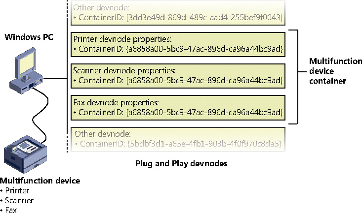
The container ID is a property that, similar to the instance ID, is reported back by the bus driver of the corresponding hardware. Then, when the device is being enumerated, all devnodes associated with the same PDO share the container ID. Because Windows already supports many buses out of the box—such as PnP-X, Bluetooth, and USB—most device drivers can simply return the bus-specific ID, from which Windows will generate the corresponding container ID. For other kinds of devices or buses, the driver can generate its own unique ID through software.
Finally, when device drivers do not supply a container ID, Windows can make educated guesses by querying the topology for the bus, when that’s available, through mechanisms such as ACPI. By understanding whether a certain device is a child of another, and whether it is removable, hot-pluggable, or user-reachable (as opposed to an internal motherboard component), Windows is able to assign container IDs to device nodes that reflect multifunction devices correctly.
The final end-user benefit of grouping devices by container IDs is visible in the Devices and Printers UI. This feature is able to display the scanner, printer, and faxing components of an all-in-one printer as a single graphical element instead of three distinct devices. For example, in Figure 6-39, the HP 6830 printer/fax/scanner is identified as a single device.

Driver support for Plug and Play
To support Plug and Play, a driver must implement a Plug and Play dispatch routine (IRP_MJ_PNP), a power-management dispatch routine (IRP_MJ_POWER, described in the section “The power manager” later in this chapter), and an add-device routine. Bus drivers must support Plug and Play requests that are different than the ones that function or filter drivers support, however. For example, when the PnP manager guides device enumeration during the system boot, it asks bus drivers for a description of the devices that they find on their respective buses through PnP IRPs.
Function and filter drivers prepare to manage their devices in their add-device routines, but they don’t actually communicate with the device hardware. Instead, they wait for the PnP manager to send a start-device command (IRP_MN_START_DEVICE minor PnP IRP code) for the device to their Plug and Play dispatch routine. Before sending the start-device command, the PnP manager performs resource arbitration to decide what resources to assign the device. The start-device command includes the resource assignment that the PnP manager determines during resource arbitration. When a driver receives a start-device command, it can configure its device to use the specified resources. If an application tries to open a device that hasn’t finished starting, it receives an error indicating that the device does not exist.
After a device has started, the PnP manager can send the driver additional Plug and Play commands, including ones related to the device’s removal from the system or to resource reassignment. For example, when the user invokes the remove/eject device utility, shown in Figure 6-40 (accessible by clicking the USB connector icon in the taskbar notification area), to tell Windows to eject a USB flash drive, the PnP manager sends a query-remove notification to any applications that have registered for Plug and Play notifications for the device. Applications typically register for notifications on their handles, which they close during a query-remove notification. If no applications veto the query-remove request, the PnP manager sends a query-remove command to the driver that owns the device being ejected (IRP_MN_QUERY_REMOVE_DEVICE). At that point, the driver has a chance to deny the removal or to ensure that any pending I/O operations involving the device have completed, and to begin rejecting further I/O requests aimed at the device. If the driver agrees to the remove request and no open handles to the device remain, the PnP manager next sends a remove command to the driver (IRP_MN_REMOVE_DEVICE) to request that the driver stop accessing the device and release any resources the driver has allocated on behalf of the device.

When the PnP manager needs to reassign a device’s resources, it first asks the driver whether it can temporarily suspend further activity on the device by sending the driver a query-stop command (IRP_MN_QUERY_STOP_DEVICE). The driver either agrees to the request (if doing so won’t cause data loss or corruption) or denies the request. As with a query-remove command, if the driver agrees to the request, the driver completes pending I/O operations and won’t initiate further I/O requests for the device that can’t be aborted and subsequently restarted. The driver typically queues new I/O requests so that the resource reshuffling is transparent to applications currently accessing the device. The PnP manager then sends the driver a stop command (IRP_MN_STOP_DEVICE). At that point, the PnP manager can direct the driver to assign different resources to the device and once again send the driver a start-device command for the device.
The various Plug and Play commands essentially guide a device through an operational state machine, forming a well-defined state-transition table, which is shown in Figure 6-41. (The state diagram reflects the state machine implemented by function drivers. Bus drivers implement a more complex state machine.) Each transition in Figure 6-41 is marked by its minor IRP constant name without the IRP_MN_ prefix. One state that we haven’t discussed is the one that results from the PnP manager’s command (IRP_MN_SURPRISE_REMOVAL). This command results when either a user removes a device without warning, as when the user ejects a PCMCIA card without using the remove/eject utility, or the device fails. The command tells the driver to immediately cease all interaction with the device because the device is no longer attached to the system and to cancel any pending I/O requests.

Plug-and-play driver installation
If the PnP manager encounters a device for which no driver is installed, it relies on the user-mode PnP manager to guide the installation process. If the device is detected during the system boot, a devnode is defined for the device, but the loading process is postponed until the user-mode PnP manager starts. (The user-mode PnP manager service is implemented in Umpnpmgr.dll hosted in a standard Svchost.exe instance.)
The components involved in a driver’s installation are shown in Figure 6-42. Dark-shaded objects in the figure correspond to components generally supplied by the system, whereas lighter-shaded objects are those included in a driver’s installation files. First, a bus driver informs the PnP manager of a device it enumerates using a Device ID (1). The PnP manager checks the registry for the presence of a corresponding function driver, and when it doesn’t find one, it informs the user-mode PnP manager (2) of the new device by its Device ID. The user-mode PnP manager first tries to perform an automatic install without user intervention. If the installation process involves the posting of dialog boxes that require user interaction and the currently logged-on user has administrator privileges, the user-mode PnP manager launches the Rundll32.exe application (the same application that hosts classic .cpl Control Panel utilities) to execute the Hardware Installation Wizard (3) (%SystemRoot%System32Newdev.dll). If the currently logged-on user doesn’t have administrator privileges (or if no user is logged on) and the installation of the device requires user interaction, the user-mode PnP manager defers the installation until a privileged user logs on. The Hardware Installation Wizard uses Setupapi.dll and CfgMgr32.dll (configuration manager) API functions to locate INF files that correspond to drivers that are compatible with the detected device. This process might involve having the user insert installation media containing a vendor’s INF files, or the wizard might locate a suitable INF file in the driver store (%SystemRoot%System32DriverStore) that contains drivers that ship with Windows or others that are downloaded through Windows Update. Installation is performed in two steps. In the first, the third-party driver developer imports the driver package into the driver store, and in the second, the system performs the actual installation, which is always done through the %SystemRoot%System32Drvinst.exe process.

To find drivers for the new device, the installation process gets a list of hardware IDs (discussed earlier) and compatible IDs from the bus driver. Compatible IDs are more generic—for example a USB mouse from a specific vendor might have a special button that does something unique, but a compatible ID for a generic mouse can utilize a more generic driver that ships with Windows if the specific driver is not available and at least provide the basic, common functionality of a mouse.
These IDs describe all the various ways the hardware might be identified in a driver installation file (INF). The lists are ordered so that the most specific description of the hardware is listed first. If matches are found in multiple INFs, the following points apply:
![]() More-precise matches are preferred over less-precise matches.
More-precise matches are preferred over less-precise matches.
![]() Digitally signed INFs are preferred over unsigned ones.
Digitally signed INFs are preferred over unsigned ones.
![]() Newer signed INFs are preferred over older signed ones.
Newer signed INFs are preferred over older signed ones.
![]() Note
Note
If a match is found based on a compatible ID, the Hardware Installation wizard can prompt for media in case a more up-to-date driver came with the hardware.
The INF file locates the function driver’s files and contains instructions that fill in the driver’s enumeration and class keys in the registry, copy required files, and the INF file might direct the Hardware Installation Wizard to (4) launch class or device co-installer DLLs that perform class-specific or device-specific installation steps, such as displaying configuration dialog boxes that let the user specify settings for a device. Finally, when the drivers that make up a devnode load, the device/driver stack is built (5).
Before installing a driver, the user-mode PnP manager checks the system’s driver-signing policy. If the settings specify that the system should block or warn of the installation of unsigned drivers, the user-mode PnP manager checks the driver’s INF file for an entry that locates a catalog (a file that ends with the .cat extension) containing the driver’s digital signature.
Microsoft’s WHQL tests the drivers included with Windows and those submitted by hardware vendors. When a driver passes the WHQL tests, it is “signed” by Microsoft. This means that WHQL obtains a hash, or unique value representing the driver’s files, including its image file, and then cryptographically signs it with Microsoft’s private driver-signing key. The signed hash is stored in a catalog file and included on the Windows installation media or returned to the vendor that submitted the driver for inclusion with its driver.
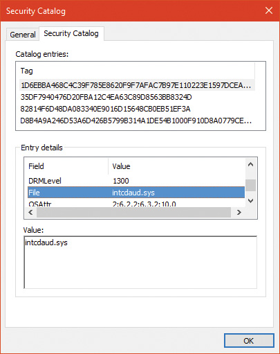
As it installs a driver, the user-mode PnP manager extracts the driver’s signature from its catalog file, decrypts the signature using the public half of Microsoft’s driver-signing private/public key pair, and compares the resulting hash with a hash of the driver file it’s about to install. If the hashes match, the driver is verified as having passed WHQL testing. If a driver fails the signature verification, the user-mode PnP manager acts according to the settings of the system driver-signing policy, either failing the installation attempt, warning the user that the driver is unsigned, or silently installing the driver.
Drivers installed using setup programs that manually configure the registry and copy driver files to a system and driver files that are dynamically loaded by applications aren’t checked for signatures by the PnP manager’s signing policy. Instead, they are checked by the kernel-mode code-signing policy described in Chapter 8 in Part 2. Only drivers installed using INF files are validated against the PnP manager’s driver-signing policy.
![]() Note
Note
The user-mode PnP manager also checks whether the driver it’s about to install is on the protected driver list maintained by Windows Update and, if so, blocks the installation with a warning to the user. Drivers that are known to have incompatibilities or bugs are added to the list and blocked from installation.
General driver loading and installation
The preceding section showed how drivers for hardware devices are discovered and loaded by the PnP manager. These drivers mostly load “on demand,” meaning such a driver is not loaded unless needed—a device that the driver is responsible for enters the system; conversely, if all devices managed by a driver are removed, the driver will be unloaded.
More generally, the Software key in the registry holds settings for drivers (as well as Windows Services). Although services are managed within the same registry key, they are user-mode programs and have no connection to kernel drivers (although the Service Control Manager can be used to load both services and device drivers). This section focuses on drivers; for a complete treatment of services, see Chapter 9 in Part 2.
Driver loading
Each subkey under the Software key (HKLMSystemCurrentControlSetServices) holds a set of values that control some static aspects of a driver (or service). One such value, ImagePath, was encountered already when we discussed the loading process of PnP drivers. Figure 6-36 shows an example of a driver key and Table 6-8 summarizes the most important values in a driver’s Software key (see Chapter 9 in Part 2 for a complete list).
The Start value indicates the phase in which a driver (or service) is loaded. There are two main differences between device drivers and services in this regard:
![]() Only device drivers can specify
Only device drivers can specify Start values of boot-start (0) or system-start (1). This is because at these phases, no user mode exists yet, so services cannot be loaded.
![]() Device drivers can use the
Device drivers can use the Group and Tag values (not shown in Table 6-8) to control the order of loading within a phase of the boot, but unlike services, they can’t specify DependOnGroup or DependOnService values (see Chapter 9 in Part 2 for more details).

Chapter 11, “Startup and shutdown, in Part 2 describes the phases of the boot process and explains that a driver Start value of 0 means that the operating system loader loads the driver. A Start value of 1 means that the I/O manager loads the driver after the executive subsystems have finished initializing. The I/O manager calls driver initialization routines in the order that the drivers load within a boot phase. Like Windows services, drivers use the Group value in their registry key to specify which group they belong to; the registry value HKLMSYSTEMCurrentControlSetControlServiceGroupOrderList determines the order that groups are loaded within a boot phase.
A driver can further refine its load order by including a Tag value to control its order within a group. The I/O manager sorts the drivers within each group according to the Tag values defined in the drivers’ registry keys. Drivers without a tag go to the end of the list in their group. You might assume that the I/O manager initializes drivers with lower-number tags before it initializes drivers with higher-number tags, but such isn’t necessarily the case. The registry key HKLMSYSTEMCurrentControlSetControlGroupOrderList defines tag precedence within a group; with this key, Microsoft and device-driver developers can take liberties with redefining the integer number system.
![]() Note
Note
The use of Group and Tag is reminiscent from the early Windows NT days. These tags are rarely used in practice. Most drivers should not have dependencies on other drivers (only on kernel libraries linked to the driver, such as NDIS.sys).
Here are the guidelines by which drivers set their Start value:
![]() Non–Plug and Play drivers set their
Non–Plug and Play drivers set their Start value to reflect the boot phase they want to load in.
![]() Drivers, including both Plug and Play and non–Plug and Play drivers, that must be loaded by the boot loader during the system boot specify a
Drivers, including both Plug and Play and non–Plug and Play drivers, that must be loaded by the boot loader during the system boot specify a Start value of boot-start (0). Examples include system bus drivers and the boot file-system driver.
![]() A driver that isn’t required for booting the system and that detects a device that a system bus driver can’t enumerate specifies a
A driver that isn’t required for booting the system and that detects a device that a system bus driver can’t enumerate specifies a Start value of system-start (1). An example is the serial port driver, which informs the PnP manager of the presence of standard PC serial ports that were detected by Setup and recorded in the registry.
![]() A non–Plug and Play driver or file-system driver that doesn’t have to be present when the system boots specifies a
A non–Plug and Play driver or file-system driver that doesn’t have to be present when the system boots specifies a Start value of auto-start (2). An example is the Multiple Universal Naming Convention (UNC) Provider (MUP) driver, which provides support for UNC-based path names to remote resources (for example, \RemoteComputerNameSomeShare).
![]() Plug and Play drivers that aren’t required to boot the system specify a
Plug and Play drivers that aren’t required to boot the system specify a Start value of demand-start (3). Examples include network adapter drivers.
The only purpose that the Start values for Plug and Play drivers and drivers for enumerable devices have is to ensure that the operating system loader loads the driver—if the driver is required for the system to boot successfully. Beyond that, the PnP manager’s device enumeration process determines the load order for Plug and Play drivers.
Driver installation
As we’ve seen, Plug and Play drivers require an INF file for installation. The INF includes the hardware device IDs this driver can handle and the instructions for copying files and setting registry values. Other type of drivers (such as file system drivers, file system filters and network filters) require an INF as well, which includes a unique set of values for the particular type of driver.
Software-only drivers (such as the one Process Explorer uses) can use an INF for installation, but don’t have to. These can be installed by a call to the CreateService API (or use a tool such as sc.exe that wraps it), as Process Explorer does after extracting its driver from a resource within the executable (if running with elevated permissions). As the API name suggests, it’s used to install services as well as drivers. The arguments to CreateService indicate whether it’s installing a driver or a service, the Start value and other parameters (see the Windows SDK documentation for the details). Once installed, a call to StartService loads the driver (or service), calling DriverEntry (for a driver) as usual.
A software-only driver typically creates a device object with a name its clients know. For example, Process Explorer creates a device named PROCEXP152 that is then used by Process Explorer in a Create- File call, followed by calls such as DeviceIoControl to send requests to the driver (turned into IRPs by the I/O manager). Figure 6-43 shows the Process Explorer object symbolic link (using the WinObj Sysinternals tool) in the GLOBAL?? directory (recall that the names in this directory are accessible to user mode clients) that’s created by Process Explorer the first time it’s running with elevated privileges. Notice that it points to the real device object under the Device directory and it has the same name (which is not a requirement).

The Windows Driver Foundation
The Windows Driver Foundation (WDF) is a framework for developing drivers that simplifies common tasks such as handing Plug and Play and Power IRPs correctly. WDF includes the Kernel-Mode Driver Framework (KMDF) and the User-Mode Driver Framework (UMDF). WDF is now open source and can be found at https://github.com/Microsoft/Windows-Driver-Frameworks. Table 6-9 shows the Windows version support (for Windows 7 and later) for KMDF. Table 6-10 shows the same for UMDF.

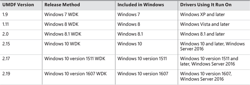
Windows 10 introduced the concept of Universal Drivers, briefly described in Chapter 2, “System architecture.” These drivers use a common set of DDIs implemented in multiple editions of Windows 10—from IoT Core, to Mobile, to desktops. Universal drivers can be built with KMDF, UMDF 2.x, or WDM. Building such drivers is relatively easy with the aid of Visual Studio, where the Target Platform setting is set to Universal. Any DDI that is outside the boundaries of Universal will be flagged by the compiler.
UMDF versions 1.x used a COM based model for programming drivers, which is a very different programming model than KMDF, which is using object-based C. UMDF 2 has been aligned with KMDF and provides an almost identical API, reducing overall cost associated with WDF driver development; in fact, UMDF 2.x drivers can be converted to KMDF if the need arises with little work. UMDF 1.x will not be discussed in this book; consult the WDK for more information.
The following sections discuss KMDF and UMDF, which essentially behave in a consistent manner, no matter the exact OS they’re running on.
Kernel-Mode Driver Framework
We’ve already discussed some details about the Windows Driver Foundation (WDF) in Chapter 2. In this section, we’ll take a deeper look at the components and functionality provided by the kernel-mode part of the framework, KMDF. Note that this section will only briefly touch on some of the core architecture of KMDF. For a much more complete overview on the subject, please refer to the Windows Driver Kit documentation.
![]() Note
Note
Most of the details presented in this section are the same for UMDF 2.x, with the exceptions discussed in the next section.
Structure and operation of a KMDF driver
First, let’s look at which kinds of drivers or devices are supported by KMDF. In general, any WDM-conformant driver should be supported by KMDF, as long as it performs standard I/O processing and IRP manipulation. KMDF is not suitable for drivers that don’t use the Windows kernel API directly but instead perform library calls into existing port and class drivers. These types of drivers cannot use KMDF because they only provide callbacks for the actual WDM drivers that do the I/O processing. Additionally, if a driver provides its own dispatch functions instead of relying on a port or class driver, IEEE 1394, ISA, PCI, PCMCIA, and SD Client (for Secure Digital storage devices) drivers can also use KMDF.
Although KMDF provides an abstraction on top of WDM, the basic driver structure shown earlier also generally applies to KMDF drivers. At their core, KMDF drivers must have the following functions:
![]() An initialization routine Like any other driver, a KMDF driver has a
An initialization routine Like any other driver, a KMDF driver has a DriverEntry function that initializes the driver. KMDF drivers initiate the framework at this point and perform any configuration and initialization steps that are part of the driver or part of describing the driver to the framework. For non–Plug and Play drivers, this is where the first device object should be created.
![]() An add-device routine KMDF driver operation is based on events and callbacks (described shortly), and the
An add-device routine KMDF driver operation is based on events and callbacks (described shortly), and the EvtDriverDeviceAdd callback is the single most important one for PnP devices because it receives notifications when the PnP manager in the kernel enumerates one of the driver’s devices.
![]() One or more
One or more EvtIo* routines Similar to a WDM driver’s dispatch routines, these callback routines handle specific types of I/O requests from a particular device queue. A driver typically creates one or more queues in which KMDF places I/O requests for the driver’s devices. These queues can be configured by request type and dispatching type.
The simplest KMDF driver might need to have only an initialization and add-device routine because the framework will provide the default, generic functionality that’s required for most types of I/O processing, including power and Plug and Play events. In the KMDF model, events refer to run-time states to which a driver can respond or during which a driver can participate. These events are not related to the synchronization primitives (synchronization is discussed in Chapter 8 in Part 2), but are internal to the framework.
For events that are critical to a driver’s operation, or that need specialized processing, the driver registers a given callback routine to handle this event. In other cases, a driver can allow KMDF to perform a default, generic action instead. For example, during an eject event (EvtDeviceEject), a driver can choose to support ejection and supply a callback or to fall back to the default KMDF code that will tell the user that the device does not support ejection. Not all events have a default behavior, however, and callbacks must be provided by the driver. One notable example is the EvtDriverDeviceAdd event just described that is at the core of any Plug and Play driver.
KMDF object model
The KMDF object model is object-based, with properties, methods and events, implemented in C, much like the model for the kernel, but it does not make use of the object manager. Instead, KMDF manages its own objects internally, exposing them as handles to drivers and keeping the actual data structures opaque. For each object type, the framework provides routines to perform operations on the object (called methods), such as WdfDeviceCreate, which creates a device. Additionally, objects can have specific data fields or members that can be accessed by Get/Set (used for modifications that should never fail) or Assign/Retrieve APIs (used for modifications that can fail), which are called properties. For example, the WdfInterruptGetInfo function returns information on a given interrupt object (WDFINTERRUPT).
Also unlike the implementation of kernel objects, which all refer to distinct and isolated object types, KMDF objects are all part of a hierarchy—most object types are bound to a parent. The root object is the WDFDRIVER structure, which describes the actual driver. The structure and meaning is analogous to the DRIVER_OBJECT structure provided by the I/O manager, and all other KMDF structures are children of it. The next most important object is WDFDEVICE, which refers to a given instance of a detected device on the system, which must have been created with WdfDeviceCreate. Again, this is analogous to the DEVICE_OBJECT structure that’s used in the WDM model and by the I/O manager. Table 6-11 lists the object types supported by KMDF.
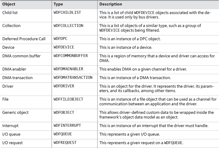
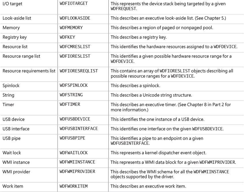
For each of these objects, other KMDF objects can be attached as children. Some objects have only one or two valid parents, while others can be attached to any parent. For example, a WDFINTERRUPT object must be associated with a given WDFDEVICE, but a WDFSPINLOCK or WDFSTRING object can have any object as a parent. This allows for fine-grained control over their validity and usage and the reduction of global state variables. Figure 6-44 shows the entire KMDF object hierarchy.
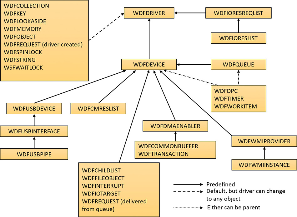
The associations mentioned earlier and shown in Figure 6-44 are not necessarily immediate. The parent must simply be on the hierarchy chain, meaning one of the ancestor nodes must be of this type. This relationship is useful to implement because object hierarchies affect not only an object’s locality but also its lifetime. Each time a child object is created, a reference count is added to it by its link to its parent. Therefore, when a parent object is destroyed, all the child objects are also destroyed, which is why associating objects such as WDFSTRING or WDFMEMORY with a given object instead of the default WDFDRIVER object can automatically free up memory and state information when the parent object is destroyed.
Closely related to the concept of hierarchy is KMDF’s notion of object context. Because KMDF objects are opaque (as discussed) and are associated with a parent object for locality, it becomes important to allow drivers to attach their own data to an object in order to track certain specific information outside the framework’s capabilities or support. Object contexts allow all KMDF objects to contain such information. They also allow multiple object context areas, which permit multiple layers of code inside the same driver to interact with the same object in different ways. In WDM, the device extension custom data structure allows such information to be associated with a given device, but with KMDF even a spinlock or string can contain context areas. This extensibility enables each library or layer of code responsible for processing an I/O request to interact independently of other code, based on the context area that it works with.
Finally, KMDF objects are also associated with a set of attributes, shown in Table 6-12. These attributes are usually configured to their defaults, but the values can be overridden by the driver when creating the object by specifying a WDF_OBJECT_ATTRIBUTES structure (similar to the object manager’s OBJECT_ATTRIBUTES structure that’s used when creating a kernel object).

KMDF I/O model
The KMDF I/O model follows the WDM mechanisms discussed earlier in this chapter. In fact, you can even think of the framework itself as a WDM driver, since it uses kernel APIs and WDM behavior to abstract KMDF and make it functional. Under KMDF, the framework driver sets its own WDM-style IRP dispatch routines and takes control of all IRPs sent to the driver. After being handled by one of three KMDF I/O handlers (described shortly), it then packages these requests in the appropriate KMDF objects, inserts them in the appropriate queues (if required), and performs driver callback if the driver is interested in those events. Figure 6-45 describes the flow of I/O in the framework.
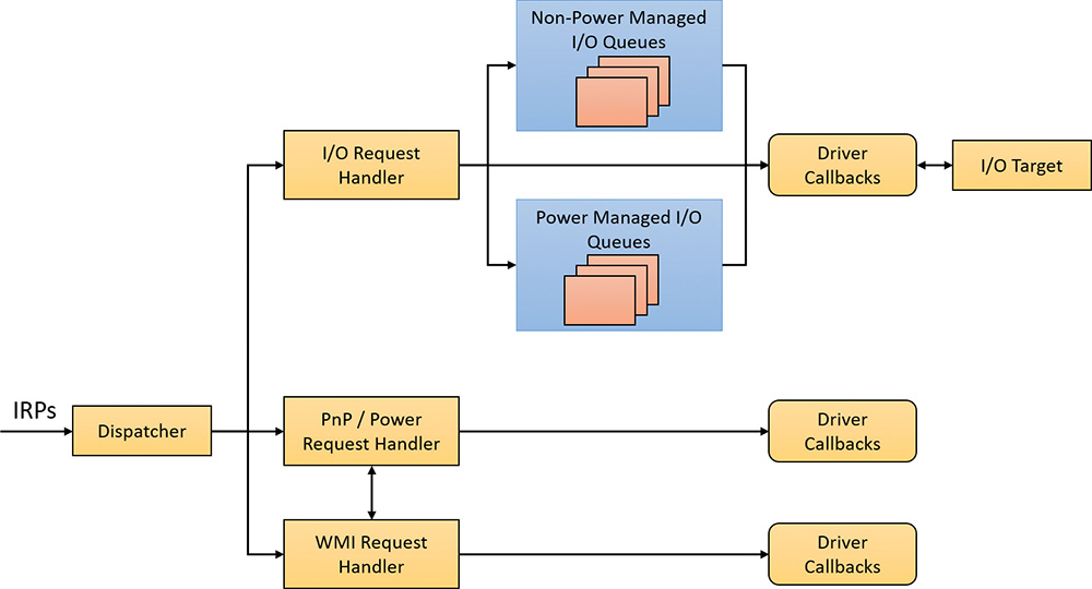
Based on the IRP processing discussed previously for WDM drivers, KMDF performs one of the following three actions:
![]() It sends the IRP to the I/O handler, which processes standard device operations.
It sends the IRP to the I/O handler, which processes standard device operations.
![]() It sends the IRP to the PnP and power handler that processes these kinds of events and notifies other drivers if the state has changed.
It sends the IRP to the PnP and power handler that processes these kinds of events and notifies other drivers if the state has changed.
![]() It sends the IRP to the WMI handler, which handles tracing and logging.
It sends the IRP to the WMI handler, which handles tracing and logging.
These components then notify the driver of any events it registered for, potentially forward the request to another handler for further processing, and then complete the request based on an internal handler action or as the result of a driver call. If KMDF has finished processing the IRP but the request itself has still not been fully processed, KMDF will take one of the following actions:
![]() For bus drivers and function drivers, it completes the IRP with
For bus drivers and function drivers, it completes the IRP with STATUS_INVALID_DEVICE_REQUEST.
![]() For filter drivers, it forwards the request to the next lower driver.
For filter drivers, it forwards the request to the next lower driver.
I/O processing by KMDF is based on the mechanism of queues (WDFQUEUE, not the KQUEUE object discussed earlier in this chapter). KMDF queues are highly scalable containers of I/O requests (packaged as WDFREQUEST objects) and provide a rich feature set beyond merely sorting the pending I/Os for a given device. For example, queues track currently active requests and support I/O cancellation, I/O concurrency (the ability to perform and complete more than one I/O request at a time), and I/O synchronization (as noted in the list of object attributes in Table 6-12). A typical KMDF driver creates at least one queue (if not more) and associates one or more events with each queue, as well as some of the following options:
![]() The callbacks registered with the events associated with this queue.
The callbacks registered with the events associated with this queue.
![]() The power management state for the queue. KMDF supports both power-managed and non–power managed queues. For the former, the I/O handler wakes up the device when required (and when possible), arms the idle timer when the device has no I/Os queued up, and calls the driver’s I/O cancellation routines when the system is switching away from a working state.
The power management state for the queue. KMDF supports both power-managed and non–power managed queues. For the former, the I/O handler wakes up the device when required (and when possible), arms the idle timer when the device has no I/Os queued up, and calls the driver’s I/O cancellation routines when the system is switching away from a working state.
![]() The dispatch method for the queue. KMDF can deliver I/Os from a queue in sequential, parallel, or manual mode. Sequential I/Os are delivered one at a time (KMDF waits for the driver to complete the previous request), while parallel I/Os are delivered to the driver as soon as possible. In manual mode, the driver must manually retrieve I/Os from the queue.
The dispatch method for the queue. KMDF can deliver I/Os from a queue in sequential, parallel, or manual mode. Sequential I/Os are delivered one at a time (KMDF waits for the driver to complete the previous request), while parallel I/Os are delivered to the driver as soon as possible. In manual mode, the driver must manually retrieve I/Os from the queue.
![]() Whether the queue can accept zero-length buffers, such as incoming requests that don’t actually contain any data.
Whether the queue can accept zero-length buffers, such as incoming requests that don’t actually contain any data.
![]() Note
Note
The dispatch method only affects the number of requests that can be active inside a driver’s queue at one time. It does not determine whether the event callbacks themselves will be called concurrently or serially. That behavior is determined through the synchronization scope object attribute described earlier. Therefore, it is possible for a parallel queue to have concurrency disabled but still have multiple incoming requests.
Based on the mechanism of queues, the KMDF I/O handler can perform various tasks upon receiving a create, close, cleanup, write, read, or device control (IOCTL) request:
![]() For create requests, the driver can request to be immediately notified through the
For create requests, the driver can request to be immediately notified through the EvtDeviceFileCreate callback event, or it can create a non-manual queue to receive create requests. It must then register an EvtIoDefault callback to receive the notifications. Finally, if none of these methods are used, KMDF will simply complete the request with a success code, meaning that by default, applications will be able to open handles to KMDF drivers that don’t supply their own code.
![]() For cleanup and close requests, the driver will be immediately notified through
For cleanup and close requests, the driver will be immediately notified through EvtFileCleanup and EvtFileClose callbacks, if registered. Otherwise, the framework will simply complete with a success code.
![]() For write, read, and IOCTL requests, the flow shown in Figure 6-46 applies.
For write, read, and IOCTL requests, the flow shown in Figure 6-46 applies.

User-Mode Driver Framework
Windows includes a growing number of drivers that run in user mode, using the User-Mode Driver Framework (UMDF), which is part of the WDF. UMDF version 2 is aligned with KMDF in terms of object model, programming model and I/O model. The frameworks are not identical, however, because of some of the inherent differences between user mode and kernel mode. For example, some KMDF objects listed in Table 6-12 don’t exist in UMDF, including WDFCHILDLIST, DMA-related objects, WDFLOOKASIDELIST (look-aside lists can be allocated only in kernel mode), WDFIORESLIST, WDFIORESREQLIST, WDFDPC, and WMI objects. Still, most KMDF objects and concepts apply equally to UMDF 2.x.
UMDF provides several advantages over KMDF:
![]() UMDF drivers execute in user mode, so any unhandled exception crashes the UMDF host process, but not the entire system.
UMDF drivers execute in user mode, so any unhandled exception crashes the UMDF host process, but not the entire system.
![]() The UMDF host process runs with the Local Service account, which has very limited privileges on the local machine and only anonymous access in network connections. This reduces the security attack surface.
The UMDF host process runs with the Local Service account, which has very limited privileges on the local machine and only anonymous access in network connections. This reduces the security attack surface.
![]() Running in user mode means the IRQL is always 0 (
Running in user mode means the IRQL is always 0 (PASSIVE_LEVEL). Thus, the driver can always take page faults and use kernel dispatcher objects for synchronization (events, mutexes, and so on).
![]() Debugging UMDF drivers is easier than debugging KMDF drivers because the debugging setup does not require two separate machines (virtual or physical).
Debugging UMDF drivers is easier than debugging KMDF drivers because the debugging setup does not require two separate machines (virtual or physical).
The main drawback to UMDF is increased latency because of the kernel/user transitions and communication required (as described shortly). Also, some types of drivers, such as drivers for high-speed PCI devices, are simply not meant to execute in user mode and thus cannot be written with UMDF.
UMDF is designed specifically to support protocol device classes, which refers to devices that all use the same standardized, generic protocol and offer specialized functionality on top of it. These protocols currently include IEEE 1394 (FireWire), USB, Bluetooth, human interface devices (HIDs) and TCP/IP. Any device running on top of these buses (or connected to a network) is a potential candidate for UMDF. Examples include portable music players, input devices, cell phones, cameras and webcams, and so on. Two other users of UMDF are SideShow-compatible devices (auxiliary displays) and the Windows Portable Device (WPD) Framework, which supports USB-removable storage (USB bulk transfer devices). Finally, as with KMDF, it’s possible to implement software-only drivers, such as for a virtual device, in UMDF.
Unlike KMDF drivers, which run as driver objects representing a SYS image file, UMDF drivers run in a driver host process (running the image %SystemRoot%System32WUDFHost.exe), similar to a service-hosting process. The host process contains the driver itself, the User-Mode Driver Framework (implemented as a DLL), and a run-time environment (responsible for I/O dispatching, driver loading, device-stack management, communication with the kernel, and a thread pool).
As in the kernel, each UMDF driver runs as part of a stack. This can contain multiple drivers that are responsible for managing a device. Naturally, because user-mode code can’t access the kernel address space, UMDF also includes components that allow this access to occur through a specialized interface to the kernel. This is implemented by a kernel-mode side of UMDF that uses ALPC—essentially an efficient inter-process communication mechanism to talk to the run-time environment in the user-mode driver host processes. (See Chapter 8 in Part 2 for more information on ALPC.) Figure 6-47 shows the architecture of the UMDF driver model.

Figure 6-47 shows two different device stacks that manage two different hardware devices, each with a UMDF driver running inside its own driver host process. From the diagram, you can see that the following components comprise the architecture:
![]() Applications These are the clients of the drivers. They are standard Windows applications that
use the same APIs to perform I/Os as they would with a KMDF-managed or WDM-managed device. Applications don’t know (nor care) that they’re talking to a UMDF-based device, and the calls are still sent to the kernel’s I/O manager.
Applications These are the clients of the drivers. They are standard Windows applications that
use the same APIs to perform I/Os as they would with a KMDF-managed or WDM-managed device. Applications don’t know (nor care) that they’re talking to a UMDF-based device, and the calls are still sent to the kernel’s I/O manager.
![]() Windows kernel (I/O manager) Based on the application I/O APIs, the I/O manager builds the IRPs for the operations, just like for any other standard device.
Windows kernel (I/O manager) Based on the application I/O APIs, the I/O manager builds the IRPs for the operations, just like for any other standard device.
![]() Reflector The reflector is what makes UMDF “tick.” It is a standard WDM filter driver (%SystemRoot%System32DriversWUDFRd.Sys) that sits at the top of the device stack of each device that is being managed by a UMDF driver. The reflector is responsible for managing the
communication between the kernel and the user-mode driver host process. IRPs related to power management, Plug and Play, and standard I/O are redirected to the host process through ALPC. This enables the UMDF driver to respond to the I/Os and perform work, as well as be involved in the Plug and Play model, by providing enumeration, installation, and management of its devices. Finally, the reflector is responsible for keeping an eye on the driver host processes by making sure they remain responsive to requests within an adequate time to prevent drivers and applications from hanging.
Reflector The reflector is what makes UMDF “tick.” It is a standard WDM filter driver (%SystemRoot%System32DriversWUDFRd.Sys) that sits at the top of the device stack of each device that is being managed by a UMDF driver. The reflector is responsible for managing the
communication between the kernel and the user-mode driver host process. IRPs related to power management, Plug and Play, and standard I/O are redirected to the host process through ALPC. This enables the UMDF driver to respond to the I/Os and perform work, as well as be involved in the Plug and Play model, by providing enumeration, installation, and management of its devices. Finally, the reflector is responsible for keeping an eye on the driver host processes by making sure they remain responsive to requests within an adequate time to prevent drivers and applications from hanging.
![]() Driver manager The driver manager is responsible for starting and quitting the driver host processes, based on which UMDF-managed devices are present, and also for managing information on them. It is also responsible for responding to messages coming from the reflector and applying them to the appropriate host process (such as reacting to device installation). The driver manager runs as a standard Windows service implemented in %SystemRoot%System32WUDFsvc.dll (hosted in a standard Svchost.exe), and is configured for automatic startup as soon as the first UMDF driver for a device is installed. Only one instance of the driver manager runs for all driver host processes (as is always the case with services), and it must always be running to allow UMDF drivers to work.
Driver manager The driver manager is responsible for starting and quitting the driver host processes, based on which UMDF-managed devices are present, and also for managing information on them. It is also responsible for responding to messages coming from the reflector and applying them to the appropriate host process (such as reacting to device installation). The driver manager runs as a standard Windows service implemented in %SystemRoot%System32WUDFsvc.dll (hosted in a standard Svchost.exe), and is configured for automatic startup as soon as the first UMDF driver for a device is installed. Only one instance of the driver manager runs for all driver host processes (as is always the case with services), and it must always be running to allow UMDF drivers to work.
![]() Host process The host process provides the address space and run-time environment for the actual driver (WUDFHost.exe). Although it runs in the local service account, it is not actually a Windows service and is not managed by the SCM—only by the driver manager. The host process is also responsible for providing the user-mode device stack for the actual hardware, which is visible to all applications on the system. Currently, each device instance has its own device stack, which runs in a separate host process. In the future, multiple instances may share the same host process. Host processes are child processes of the driver manager.
Host process The host process provides the address space and run-time environment for the actual driver (WUDFHost.exe). Although it runs in the local service account, it is not actually a Windows service and is not managed by the SCM—only by the driver manager. The host process is also responsible for providing the user-mode device stack for the actual hardware, which is visible to all applications on the system. Currently, each device instance has its own device stack, which runs in a separate host process. In the future, multiple instances may share the same host process. Host processes are child processes of the driver manager.
![]() Kernel-mode drivers If specific kernel support for a device that is managed by a UMDF driver is needed, it is also possible to write a companion kernel-mode driver that fills that role. In this way, it is possible for a device to be managed both by a UMDF and a KMDF (or WDM) driver.
Kernel-mode drivers If specific kernel support for a device that is managed by a UMDF driver is needed, it is also possible to write a companion kernel-mode driver that fills that role. In this way, it is possible for a device to be managed both by a UMDF and a KMDF (or WDM) driver.
You can easily see UMDF in action on your system by inserting a USB flash drive with some content on it. Run Process Explorer, and you should see a WUDFHost.exe process that corresponds to a driver host process. Switch to DLL view and scroll down until you see DLLs like the ones shown in Figure 6-48.
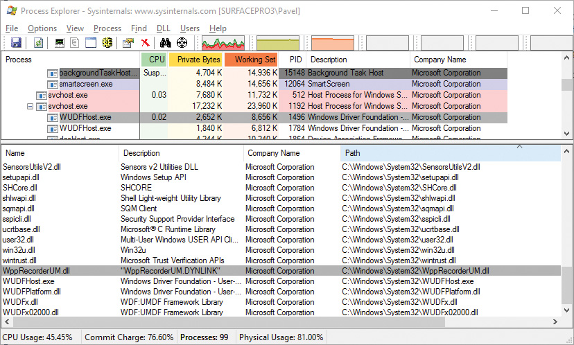
You can identify three main components, which match the architectural overview described earlier:
![]() WUDFHost.exe This is the UMDF host executable.
WUDFHost.exe This is the UMDF host executable.
![]() WUDFx02000.dll This is the UMDF 2.x framework DLL.
WUDFx02000.dll This is the UMDF 2.x framework DLL.
![]() WUDFPlatform.dll This is the run-time environment.
WUDFPlatform.dll This is the run-time environment.
The power manager
Just as Windows Plug and Play features require support from a system’s hardware, its power-management capabilities require hardware that complies with the Advanced Configuration and Power Interface (ACPI) specification, which is now part of the Unified Extensible Firmware Interface (UEFI). (The ACPI spec is available at http://www.uefi.org/specifications.)
The ACPI standard defines various power levels for a system and for devices. The six system power states are described in Table 6-13. They are referred to as S0 (fully on or working) through S5 (fully off). Each state has the following characteristics:
![]() Power consumption This is the amount of power the system consumes.
Power consumption This is the amount of power the system consumes.
![]() Software resumption This is the software state from which the system resumes when moving to a “more on” state.
Software resumption This is the software state from which the system resumes when moving to a “more on” state.
![]() Hardware latency This is the length of time it takes to return the system to the fully on state.
Hardware latency This is the length of time it takes to return the system to the fully on state.
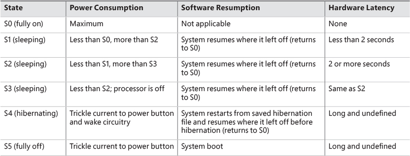
As noted in Table 6-13, states S1 through S4 are sleeping states, in which the system appears to be off because of reduced power consumption. However, in these sleeping states, the system retains enough information—either in memory or on disk—to move to S0. For states S1 through S3, enough power is required to preserve the contents of the computer’s memory so that when the transition is made to S0 (when the user or a device wakes up the computer), the power manager continues executing where it left off before the suspend.
When the system moves to S4, the power manager saves the compressed contents of memory to a hibernation file named Hiberfil.sys, which is large enough to hold the uncompressed contents of memory, in the root directory of the system volume (hidden file). (Compression is used to minimize disk I/O and to improve hibernation and resume-from-hibernation performance.) After it finishes saving memory, the power manager shuts off the computer. When a user subsequently turns on the computer, a normal boot process occurs, except that the boot manager checks for and detects a valid memory image stored in the hibernation file. If the hibernation file contains the saved system state, the boot manager launches %SystemRoot%System32Winresume.exe, which reads the contents of the file into memory, and then resumes execution at the point in memory that is recorded in the hibernation file.
On systems with hybrid sleep enabled, a user request to put the computer to sleep will actually be a combination of both the S3 state and the S4 state. While the computer is put to sleep, an emergency hibernation file will also be written to disk. Unlike typical hibernation files, which contain almost all active memory, the emergency hibernation file includes only data that could not be paged in at a later time, making the suspend operation faster than a typical hibernation (because less data is written to disk). Drivers will then be notified that an S4 transition is occurring, allowing them to configure themselves and save state just as if an actual hibernation request had been initiated. After this point, the system is put in the normal sleep state just like during a standard sleep transition. However, if the power goes out, the system is now essentially in an S4 state—the user can power on the machine, and Windows will resume from the emergency hibernation file.
![]() Note
Note
You can disable hibernation completely and gain some disk space by running powercfg /h off from an elevated command prompt.
The computer never directly transitions between states S1 and S4 (because that requires code execution, but the CPU is off in these states); instead, it must move to state S0 first. As illustrated in Figure 6-49, when the system is moving from any of states S1 through S5 to state S0, it’s said to be waking, and when it’s transitioning from state S0 to any of states S1 through S5, it’s said to be sleeping.

For devices, ACPI defines four power states, from D0 through D3. State D0 is fully on, while state D3 is fully off. The ACPI standard leaves it to individual drivers and devices to define the meanings of states D1 and D2, except that state D1 must consume an amount of power less than or equal to that consumed in state D0, and when the device is in state D2, it must consume power less than or equal to that consumed in D1.
Windows 8 (and later) splits the D3 state into two sub-states, D3-hot and D3-cold. In D3-hot state, the device is mostly turned off, but is not disconnected from its main power source, and its parent bus controller can detect the presence of the device on the bus. In D3-cold, the main power source is removed from the device, and the bus controller cannot detect the device. This state provides another opportunity for saving power. Figure 6-50 shows the device states and the possible state transitions.
Figure 6-50 shows the device states and the possible state transitions.
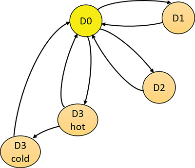
Before Windows 8, devices could only reach D3-hot state while the system is fully on (S0). The transition to D3-cold was implicit when the system went into a sleep state. Starting with Windows 8, a device’s power state can be set to D3-cold while the system is fully on. The driver that controls the device cannot put the device into D3-cold state directly; instead, it can put the device into D3-hot state, and then, depending on other devices on the same bus entering D3-hot states, the bus driver and firmware may decide to move all the devices to D3-cold. The decision whether to move the devices to D3-cold states depends on two factors: first, the actual ability of the bus driver and firmware, and second on the driver that must enable the transition to D3-cold either by specifying that in the installation INF file or by calling the SetD3DColdSupport function dynamically.
Microsoft, in conjunction with the major hardware OEMs, has defined a series of power management reference specifications that specify the device power states that are required for all devices in a particular class (for the major device classes: display, network, SCSI, and so on). For some devices, there’s no intermediate power state between fully on and fully off, which results in these states being undefined.
Connected Standby and Modern Standby
You may have noticed in the experiment above another system state called Standby (S0 Low Power Idle). Although not an official ACPI state, it is a variant of S0 known as Connected Standby on Windows 8.x and later enhanced in Windows 10 (desktop and mobile editions) and called Modern Standby. The “normal” standby state (S3 above) is sometimes referred to as Legacy Standby.
The main problem with Legacy Standby is that the system is not working, and therefore, for example, the user receives an email, the system can’t pick that up without waking to S0, which may or may not happen, depending on configuration and device capabilities. Even if the system wakes up to get that email, it won’t go immediately to sleep again. Modern Standby solves both issues.
Systems that support Modern Standby normally go into this state when the system is instructed to go to Standby. The system is technically still at S0, meaning the CPU is active and code can execute. However, desktop processes (non-UWP apps) are suspended, as well as UWP apps (most are not in the foreground and suspended anyway), but background tasks created by UWP apps are allowed to execute. For example, an email client would have a background task that periodically polls for new messages.
Being in Modern Standby also means that the system is able to wake to full S0 very quickly, sometimes referred to as Instant On. Note that not all systems support Modern Standby, as it depends on the chipset and other platform components (as can be seen in the last experiment, the system on which the experiment ran does not support Modern Standby and thus supports Legacy Standby).
For more information on Modern Standby, consult the Windows Hardware documentation at https://msdn.microsoft.com/en-us/library/windows/hardware/mt282515(v=vs.85).aspx.
Power manager operation
Windows power-management policy is split between the power manager and the individual device drivers. The power manager is the owner of the system power policy. This ownership means the power manager decides which system power state is appropriate at any given point, and when a sleep, hibernation, or shutdown is required, the power manager instructs the power-capable devices in the system to perform appropriate system power-state transitions.
The power manager decides when a system power-state transition is necessary by considering several factors:
![]() System activity level
System activity level
![]() System battery level
System battery level
![]() Shutdown, hibernate, or sleep requests from applications
Shutdown, hibernate, or sleep requests from applications
![]() User actions, such as pressing the power button
User actions, such as pressing the power button
![]() Control Panel power settings
Control Panel power settings
When the PnP manager performs device enumeration, part of the information it receives about a device is its power-management capabilities. A driver reports whether its devices support device states D1 and D2 and, optionally, the latencies, or times required, to move from states D1 through D3 to D0. To help the power manager determine when to make system power-state transitions, bus drivers also return a table that implements a mapping between each of the system power states (S0 through S5) and the device power states that a device supports.
The table lists the lowest possible device power state for each system state and directly reflects the state of various power planes when the machine sleeps or hibernates. For example, a bus that supports all four device power states might return the mapping table shown in Table 6-14. Most device drivers turn their devices completely off (D3) when leaving S0 to minimize power consumption when the machine isn’t in use. Some devices, however, such as network adapter cards, support the ability to wake up the system from a sleeping state. This ability, along with the lowest device power state in which the capability is present, is also reported during device enumeration.

Driver power operation
When the power manager decides to make a transition between system power states, it sends power commands to a driver’s power dispatch routine (IRP_MJ_POWER). More than one driver can be responsible for managing a device, but only one of the drivers is designated as the device power-policy owner. This is typically the driver that manages the FDO. This driver determines, based on the system state, a device’s power state. For example, if the system transitions between state S0 and S3, a driver might decide to move a device’s power state from D0 to D1.
Instead of directly informing the other drivers that share the management of the device of its decision, the device power-policy owner asks the power manager, via the PoRequestPowerIrp function, to tell the other drivers by issuing a device power command to their power dispatch routines. This behavior enables the power manager to control the number of power commands that are active on a system at any given time. For example, some devices in the system might require a significant amount of current to power up. The power manager ensures that such devices aren’t powered up simultaneously.
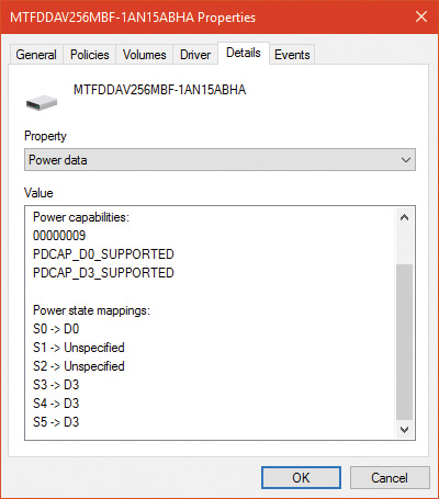
Many power commands have corresponding query commands. For example, when the system is moving to a sleep state, the power manager will first ask the devices on the system whether the transition is acceptable. A device that is busy performing time-critical operations or interacting with device hardware might reject the command, which results in the system maintaining its current system power-state setting.
EXPERIMENT: Viewing the system power capabilities and policy
lkd> !pocaps
PopCapabilities @ 0xfffff8035a98ce60
Misc Supported Features: PwrButton SlpButton Lid S3 S4 S5 HiberFile FullWake
VideoDim
Processor Features: Thermal
Disk Features:
Battery Features: BatteriesPresent
Battery 0 - Capacity: 0 Granularity: 0
Battery 1 - Capacity: 0 Granularity: 0
Battery 2 - Capacity: 0 Granularity: 0
Wake Caps
Ac OnLine Wake: Sx
Soft Lid Wake: Sx
RTC Wake: S4
Min Device Wake: Sx
Default Wake: Sx
C:WINDOWSsystem32>powercfg /list
Existing Power Schemes (* Active)
-----------------------------------
Power Scheme GUID: 381b4222-f694-41f0-9685-ff5bb260df2e (Balanced)
Power Scheme GUID: 8759706d-706b-4c22-b2ec-f91e1ef6ed38 (HP Optimized
(recommended)) *
Power Scheme GUID: 8c5e7fda-e8bf-4a96-9a85-a6e23a8c635c (High performance)
Power Scheme GUID: a1841308-3541-4fab-bc81-f71556f20b4a (Power saver)

lkd> !popolicy
SYSTEM_POWER_POLICY (R.1) @ 0xfffff8035a98cc64
PowerButton: Sleep Flags: 00000000 Event: 00000000
SleepButton: Sleep Flags: 00000000 Event: 00000000
LidClose: None Flags: 00000000 Event: 00000000
Idle: Sleep Flags: 00000000 Event: 00000000
OverThrottled: None Flags: 00000000 Event: 00000000
IdleTimeout: 0 IdleSensitivity: 90%
MinSleep: S3 MaxSleep: S3
LidOpenWake: S0 FastSleep: S3
WinLogonFlags: 1 S4Timeout: 0
VideoTimeout: 600 VideoDim: 0
SpinTimeout: 4b0 OptForPower: 0
FanTolerance: 0% ForcedThrottle: 0%
MinThrottle: 0% DyanmicThrottle: None (0)
Driver and application control of device power
In addition to responding to power manager commands related to system power-state transitions, a driver can unilaterally control the device power state of its devices. In some cases, a driver might want to reduce the power consumption of a device it controls if the device is left inactive for a period of time. Examples include monitors that support a dimmed mode and disks that support spin-down. A driver can either detect an idle device itself or use facilities provided by the power manager. If the device uses the power manager, it registers the device with the power manager by calling the PoRegisterDeviceForIdleDetection function.
This function informs the power manager of the timeout values to use to detect whether a device is idle and, if so, the device power state that the power manager should apply. The driver specifies two timeouts: one to use when the user has configured the computer to conserve energy and the other to use when the user has configured the computer for optimum performance. After calling PoRegisterDeviceForIdleDetection, the driver must inform the power manager, by calling the PoSetDeviceBusy or PoSetDeviceBusyEx functions, whenever the device is active, and then register for idle detection again to disable and re-enable it as needed. The PoStartDeviceBusy and PoEndDeviceBusy APIs are available as well, which simplify the programming logic required to achieve the behavior just described.
Although a device has control over its own power state, it does not have the ability to manipulate the system power state or to prevent system power transitions from occurring. For example, if a badly designed driver doesn’t support any low-power states, it can choose to remain on or turn itself completely off without hindering the system’s overall ability to enter a low-power state—this is because the power manager only notifies the driver of a transition and doesn’t ask for consent. Drivers do receive a power query IRP (IRP_MN_QUERY_POWER) when the system is about to transition to a lower power state. The driver may veto the request, but the power manager does not have to comply; it may delay transition if possible (e.g., the device is running on a battery that is not critically low); transition to hibernation, however, can never fail.
Although drivers and the kernel are chiefly responsible for power management, applications are also allowed to provide their input. User-mode processes can register for a variety of power notifications, such as when the battery is low or critically low, when the machine has switched from DC (battery) to AC (adapter/charger) power, or when the system is initiating a power transition. Applications can never veto these operations, and they can have up to two seconds to clean up any state necessary before a sleep transition.
Power management framework
Starting with Windows 8, the kernel provides a framework for managing power states of individual components (sometimes called functions) within a device. For example, suppose an audio device has playback and recording components, but if the playback component is active and the recording component is not, it would be beneficial to put the recording component into a lower power state. The power management framework (PoFx) provides an API that drivers can use to indicate their components’ power states and requirements. All components must support the fully-on state, identified as F0. Higher-number F-states indicate lower power states that a component may be in, where each higher F-state represents a lower power consumption and higher transition time to F0. Note that F-state management has meaning only when the device is in power state D0, because it’s not working at all in higher D-states.
The power policy owner of the device (typically the FDO) must register with PoFx by calling the PoFxRegisterDevice function. The driver passes along the following information in the call:
![]() The number of components within the device.
The number of components within the device.
![]() A set of callbacks the driver can implement to be notified by PoFx when various events occur, such as switching to active or idle state, switching the device to D0 state and sending power control codes (see the WDK for more information).
A set of callbacks the driver can implement to be notified by PoFx when various events occur, such as switching to active or idle state, switching the device to D0 state and sending power control codes (see the WDK for more information).
![]() For each component, the number of F-states it supports.
For each component, the number of F-states it supports.
![]() For each component, the deepest F-state from which the component can wake.
For each component, the deepest F-state from which the component can wake.
![]() For each component, for each F-state, the time required to return from this state to F0, the minimum amount of time the component can be in this F-state to make the transition worthwhile, and the nominal power the component consumes in this F-state. Or, it can be set to indicate that the power consumption is negligible and is not worth considering when PoFx decides to wake several components simultaneously.
For each component, for each F-state, the time required to return from this state to F0, the minimum amount of time the component can be in this F-state to make the transition worthwhile, and the nominal power the component consumes in this F-state. Or, it can be set to indicate that the power consumption is negligible and is not worth considering when PoFx decides to wake several components simultaneously.
PoFx uses this information—combined with information from other devices and system-wide power state information, such as the current power profile—to make intelligent decisions for which power F-state a particular component should be in. The challenge is to reconcile two conflicting objectives: first, ensuring that an idle component consumes as little power as possible, and second, making sure a component can transition to the F0 state quickly enough so that the component is perceived as always on and always connected.
The driver must notify PoFx when a component needs to be active (F0 state) by calling PoFxActivate-Component. Sometime after this call, the corresponding callback is invoked by PoFx, indicating to the driver that the component is now at F0. Conversely, when the driver determines the component is not currently needed, it calls PoFxIdleComponent to tell PoFx, which responds by transitioning the component to a lower-power F-state and notifies the driver once it does.
Performance state management
The mechanisms just described allow a component in an idle condition (non-F0 states) to consume less power than in F0. But some components can consume less power even in state F0, related to the actual work a device is doing. For example, a graphic card may be able to use less power when showing a mostly static display, whereas it would need higher power when rendering 3D content in 60 frames per second.
In Windows 8.x, such drivers would have to implement a propriety performance state selection algorithm and notify an OS service called platform extension plug-in (PEP). PEP is specific to a particular line of processors or system on a chip (SoC). This makes the driver code tightly coupled to the PEP.
Windows 10 extends the PoFx API for performance state management, prompting the driver code to use standard APIs and not worry about the particular PEP on the platform. For each component, PoFx provides the following types of performance states:
![]() A discrete number of states in the frequency (Hz), bandwidth (bits per second), or an opaque number meaningful to the driver.
A discrete number of states in the frequency (Hz), bandwidth (bits per second), or an opaque number meaningful to the driver.
![]() A continuous distribution of states between a minimum and maximum (frequency, bandwidth, or custom).
A continuous distribution of states between a minimum and maximum (frequency, bandwidth, or custom).
An example of this is for a graphic card to define a discrete set of frequencies in which it can operate, thus indirectly affecting its power consumption. Similar performance sets could be defined for its bandwidth usage, if appropriate.
To register with PoFx for performance state management, a driver must first register the device with PoFx (PoFxRegisterDevice) as described in the previous section. Then, the driver calls PoFxRegisterComponentPerfStates, passing performance details (discrete or range-based, frequency, bandwidth, or custom) and a callback when state changes actually occur.
When a driver decides that a component should change performance state, it calls PoFxIssueComponentPerfStateChange or PoFxIssueComponentPerfStateChangeMultiple. These calls request the PEP to place the component in the specified state (based on the provided index or value, depending on whether the set is for a discrete state or range-based). The driver may also specify that the call should be synchronous, asynchronous or “don’t care,” in which case the PEP decides. Either way, PoFx will eventually call into the driver-registered callback with the performance state, which may be the requested one, but it can also be denied by the PEP. If accepted, the driver should make the appropriate calls to its hardware to make the actual change. If the PEP denies the request, the driver may try again with a new call to one of the aforementioned functions. Only a single call can be made before the driver’s callback is invoked.
Power availability requests
Applications and drivers cannot veto sleep transitions that are already initiated. However, certain scenarios demand a mechanism for disabling the ability to initiate sleep transitions when a user is interacting with the system in certain ways. For example, if the user is currently watching a movie and the machine would normally go idle (based on a lack of mouse or keyboard input after 15 minutes), the media player application should have the capability to temporarily disable idle transitions as long as the movie is playing. You can probably imagine other power-saving measures that the system would normally undertake, such as turning off or even just dimming the screen, that would also limit your enjoyment of visual media. In legacy versions of Windows, SetThreadExecutionState was a user-mode API capable of controlling system and display idle transitions by informing the power manager that a user was still present on the machine. However, this API did not provide any sort of diagnostic capabilities, nor did it allow sufficient granularity for defining the availability request. Also, drivers could not issue their own requests, and even user applications had to correctly manage their threading model, because these requests were at the thread level, not at the process or system level.
Windows now supports power request objects, which are implemented by the kernel and are bona-fide object manager–defined objects. You can use the WinObj utility from Sysinternals (more details on this tool are in Chapter 8 in Part 2) and see the PowerRequest object type in the ObjectTypes directory, or use the !object kernel debugger command on the ObjectTypesPowerRequest object type, to validate this.
Power availability requests are generated by user-mode applications through the PowerCreate-Request API and then enabled or disabled with the PowerSetRequest and PowerClearRequest APIs, respectively. In the kernel, drivers use PoCreatePowerRequest, PoSetPowerRequest, and PoClear-PowerRequest. Because no handles are used, PoDeletePowerRequest is needed to remove the reference on the object (while user mode can simply use CloseHandle).
There are four kinds of requests that can be used through the Power Request API:
![]() System request This type request asks that the system not automatically go to sleep due to the idle timer (although the user can still close the lid to enter sleep, for example).
System request This type request asks that the system not automatically go to sleep due to the idle timer (although the user can still close the lid to enter sleep, for example).
![]() Display request This type of request does the same as a system request, but for the display.
Display request This type of request does the same as a system request, but for the display.
![]() Away-mode request This is a modification to the normal sleep (S3 state) behavior of Windows, which is used to keep the computer in full powered-on mode but with the display and sound card turned off, making it appear to the user as though the machine is really sleeping. This behavior is normally used only by specialized set-top boxes or media center devices when media delivery must continue even though the user has pressed a physical sleep button, for example.
Away-mode request This is a modification to the normal sleep (S3 state) behavior of Windows, which is used to keep the computer in full powered-on mode but with the display and sound card turned off, making it appear to the user as though the machine is really sleeping. This behavior is normally used only by specialized set-top boxes or media center devices when media delivery must continue even though the user has pressed a physical sleep button, for example.
![]() Execution required request This type of request (available starting with Windows 8 and Server 2012) requests a UWP app process continue execution even if normally the Process Lifecycle Manager (PLM) would have terminated it (for whatever reason); the extended length of time depends on factors such as the power policy settings. This request type is only supported for systems that support Modern Standby, otherwise this request is interpreted as a system request.
Execution required request This type of request (available starting with Windows 8 and Server 2012) requests a UWP app process continue execution even if normally the Process Lifecycle Manager (PLM) would have terminated it (for whatever reason); the extended length of time depends on factors such as the power policy settings. This request type is only supported for systems that support Modern Standby, otherwise this request is interpreted as a system request.
Conclusion
The I/O system defines the model of I/O processing on Windows and performs functions that are common to or required by more than one driver. Its chief responsibilities are to create IRPs representing I/O requests and to shepherd the packets through various drivers, returning results to the caller when an I/O is complete. The I/O manager locates various drivers and devices by using I/O system objects, including driver and device objects. Internally, the Windows I/O system operates asynchronously to achieve high performance and provides both synchronous and asynchronous I/O capabilities to user-mode applications.
Device drivers include not only traditional hardware device drivers but also file-system, network, and layered filter drivers. All drivers have a common structure and communicate with each other and the I/O manager by using common mechanisms. The I/O system interfaces allow drivers to be written in a high-level language to lessen development time and to enhance their portability. Because drivers present a common structure to the operating system, they can be layered one on top of another to achieve modularity and reduce duplication between drivers. By using the Universal DDI baseline, drivers can target multiple devices and form factors with no code changes.
Finally, the role of the PnP manager is to work with device drivers to dynamically detect hardware devices and to build an internal device tree that guides hardware device enumeration and driver installation. The power manager works with device drivers to move devices into low-power states when applicable to conserve energy and prolong battery life.
The next chapter touches on one of the most important aspects of today’s computer systems: security.