CHAPTER NINE
WAREHOUSE LAYOUT OPTIMIZATION
9.1 Space Requirements Planning
9.5 Material-Handling Equipment
9.6 Maximize Space Efficiencies
9.7 Expansion/Contraction Planning
Warehouse layout is much like puzzle piecing. The puzzle pieces are the warehouse activities of receiving, receiving staging, pallet storage and retrieval, case picking, piece picking, packing, order assembly, shipping staging, and so on. As with a puzzle, it is impossible to complete until all the individual pieces have been shaped and sized. The individual shaping and sizing of those individual pieces were completed in previous chapters, where we selected equipment and determined space requirements for each activity. Our seven-step RightPaths methodology for putting those activities together into an efficient warehouse layout is the subject of this chapter.
1. Determine space requirements for all warehouse functions.
2. Locate functions with high adjacency requirements close to one another.
3. Assign activities with high storage requirements to high-bay space and labor-intensive processes in low-bay space.
4. Determine flow paths.
5. Assign the optimal material-handling method to each flow path.
6. Minimize space requirements.
7. Develop and document expansion/contraction strategies.
9.1 Space Requirements Planning
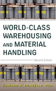
Warehouse layouts should be based primarily on the space requirements for and the interrelationships between warehouse activities. The first step in laying out a warehouse is to determine the overall space requirements for all warehouse activities. The Space Requirements Optimization from our RightHouse Layout Optimization System optimizes and summarizes long-term space requirements (Figure 9.1).
Figure 9.1 Warehouse space requirements optimization.
Storage Requirements Planning
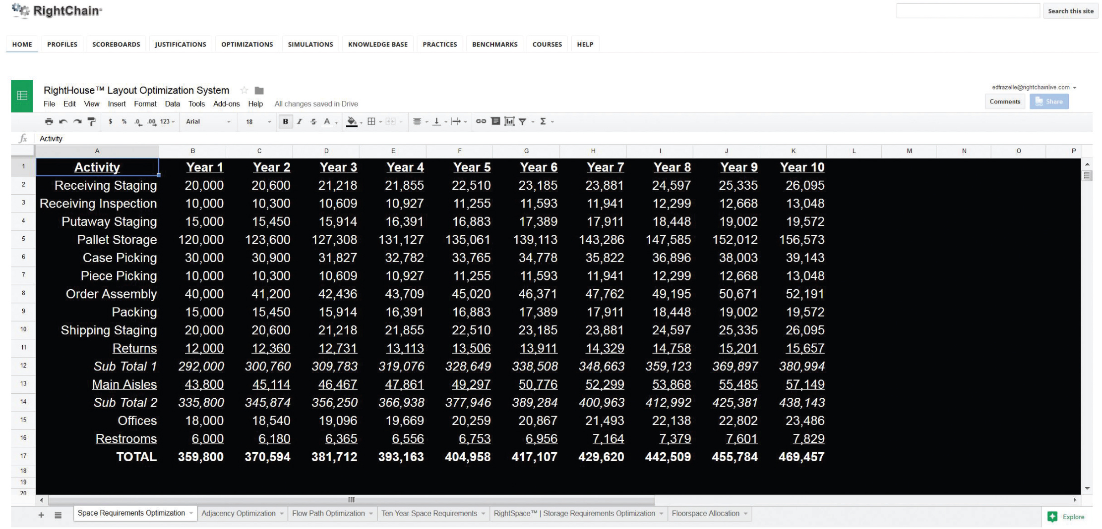
One of the most difficult decisions to make in storage-space planning is the portion of the peak storage requirements to accommodate. If the duration of the peak is short-lived and the peak-to-average storage ratio is high, then outside warehousing and/or trailer storage should be considered to accommodate the peak storage requirements (Figure 9.2). If the duration of the peak is for an extended period and the peak-to-average storage ratio is low, then the storage area should be sized at or very near peak requirements (Figure 9.3).
Figure 9.2 Storage capacity requirements with a short-lived high peak-to-average storage ratio.
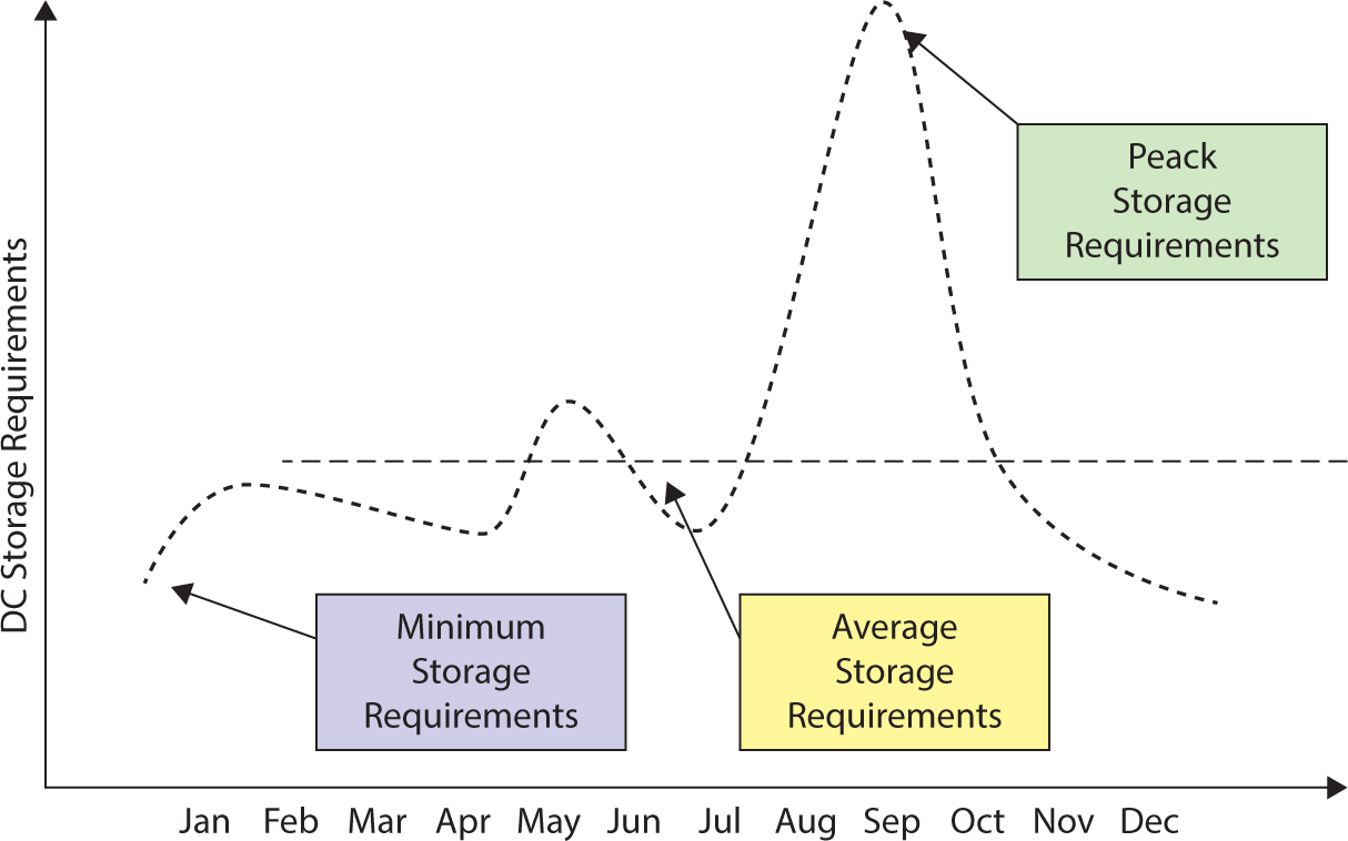
Figure 9.3 Storage capacity requirements over time with a low peak-to-average storage ratio.
Occupancy versus Productivity
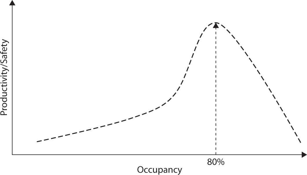
Another important consideration in storage space requirements planning is the portion of warehouse locations that will be occupied for planning purposes. As the utilization of storage locations exceeds 85 percent in non-real-time warehouses and 90 percent in real-time warehouses, the productivity and safety of the operations decline dramatically (Figure 9.4).
Figure 9.4 Warehouse productivity versus warehouse occupancy.
Stihl Corporation
Stihl Corporation recently asked us to assist them in projecting their long-term warehouse space requirements. Because pallet storage occupies the most space, we began by computing the storage-space requirements for pallets. The computations and scenarios are described next and illustrated in Figure 9.5.
Figure 9.5 Storage requirements optimization.
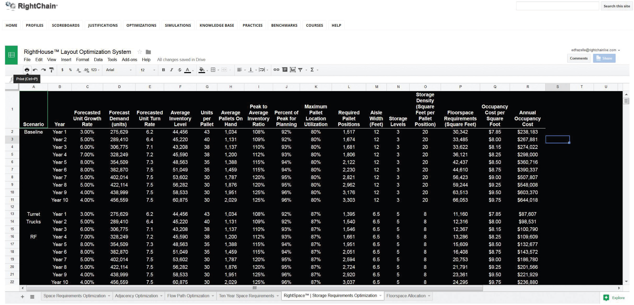
1. Divide forecasted unit sales by annual inventory turns to compute the average unit inventory.
2. Divide the average unit inventory by the average units per pallet to compute the average pallet inventory.
3. Multiply the average pallet inventory by the ratio of peak-to-average inventory to compute the peak pallet inventory.
4. Multiply the peak pallet inventory by the portion of peak inventory used for storage planning purposes to compute the effective pallet storage capacity.
5. Divide the effective pallet storage capacity by the location utilization factor (typically 85 percent for single-deep pallet storage) to compute the required number of pallet storage locations.
6. Multiply the required number of pallet storage locations by the storage density (square feet per pallet computed as a function of the aisle width and storage height) to compute the floor-space requirements.
7. Apply the annual occupancy cost rate to estimate the annual occupancy costs.
9.2 Adjacency Optimization
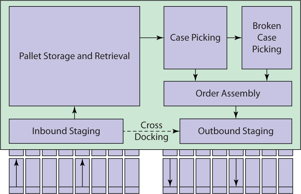
Based primarily on material flow patterns, activities with high adjacency requirements should be located close to one another. For example, reserve storage should be located near receiving. The same can be said for receiving and cross-docking, cross-docking and shipping, case picking and pallet storage, case picking and broken-case picking and picking shipping. If we decide to locate receiving and shipping near one another, then these natural flow relationships lead to a U-shaped flow design.
We use warehouse activity relationship charting to document adjacency requirements. It is used to suggest the location of processes and functions relative to one another in a block layout. In the example in Figure 9.6, we simply record under each interprocess relationship the importance of locating the processes adjacent to one another. For example, it is critical that reserve storage be adjacent to receiving staging for efficient put-away (Figure 9.7). Computer-aided facility layout tools take these adjacency requirements, the floor-space requirements of each process, and the location of fixed objects as inputs and compute an optimal block layout for a facility. Figure 9.8 illustrates conversion of our adjacency optimization into a block layout for a Honda parts distribution center. Computer-aided design tools allow us to convert the block layout into a detailed facility design. Figure 9.9 illustrates our conversion of the block layout for the Honda parts distribution center into a detailed distribution center layout.
Figure 9.6 Adjacency optimization from the RightHouse Layout Optimization System.
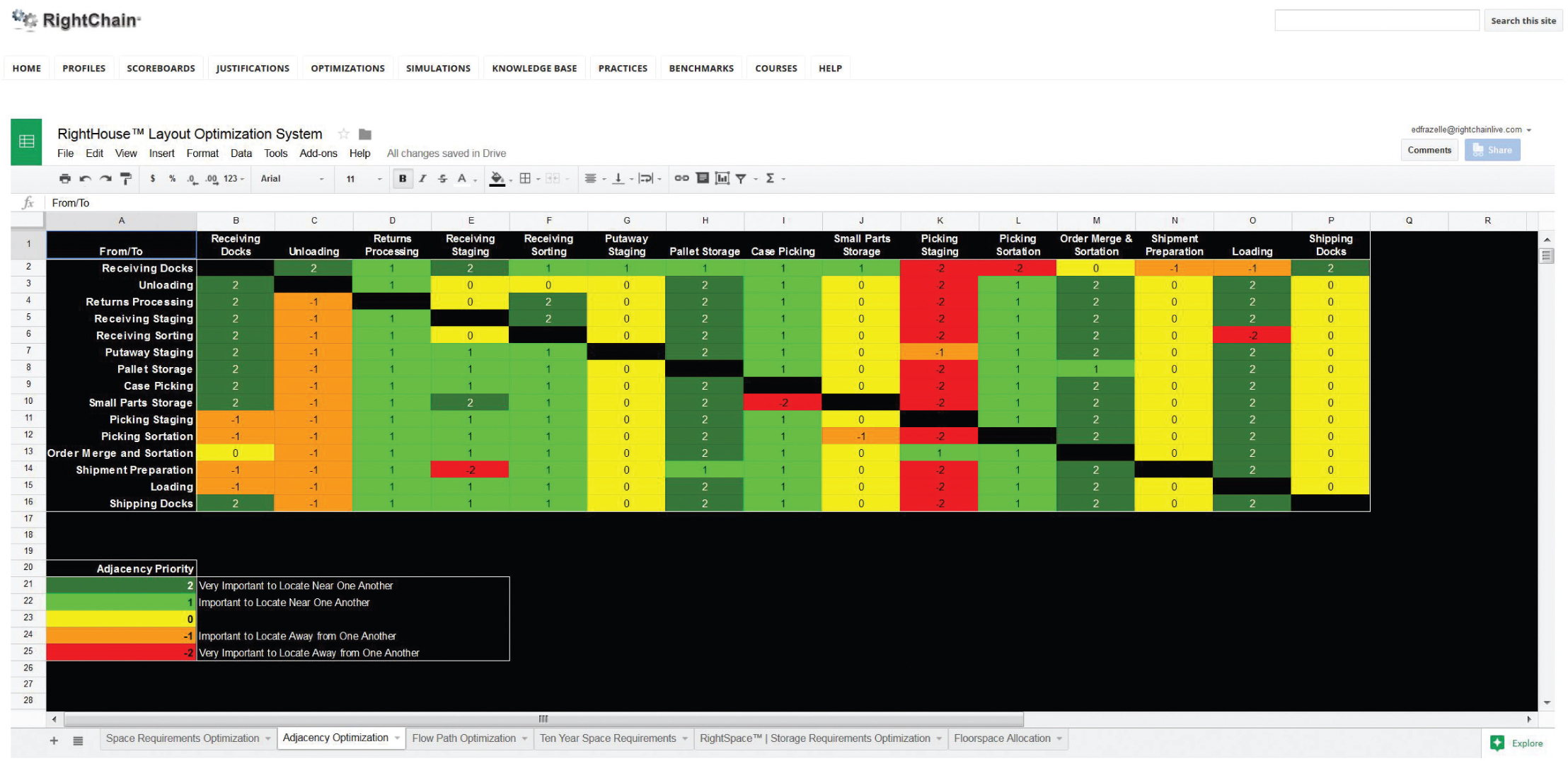
Figure 9.7 Block layout from the RightHouse Layout Optimization System.
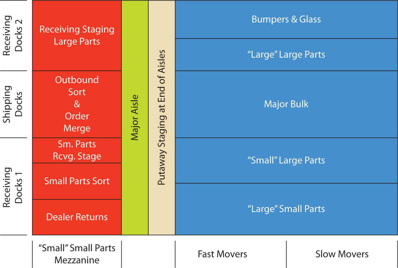
Figure 9.8 Detailed layout for a Honda parts distribution center.
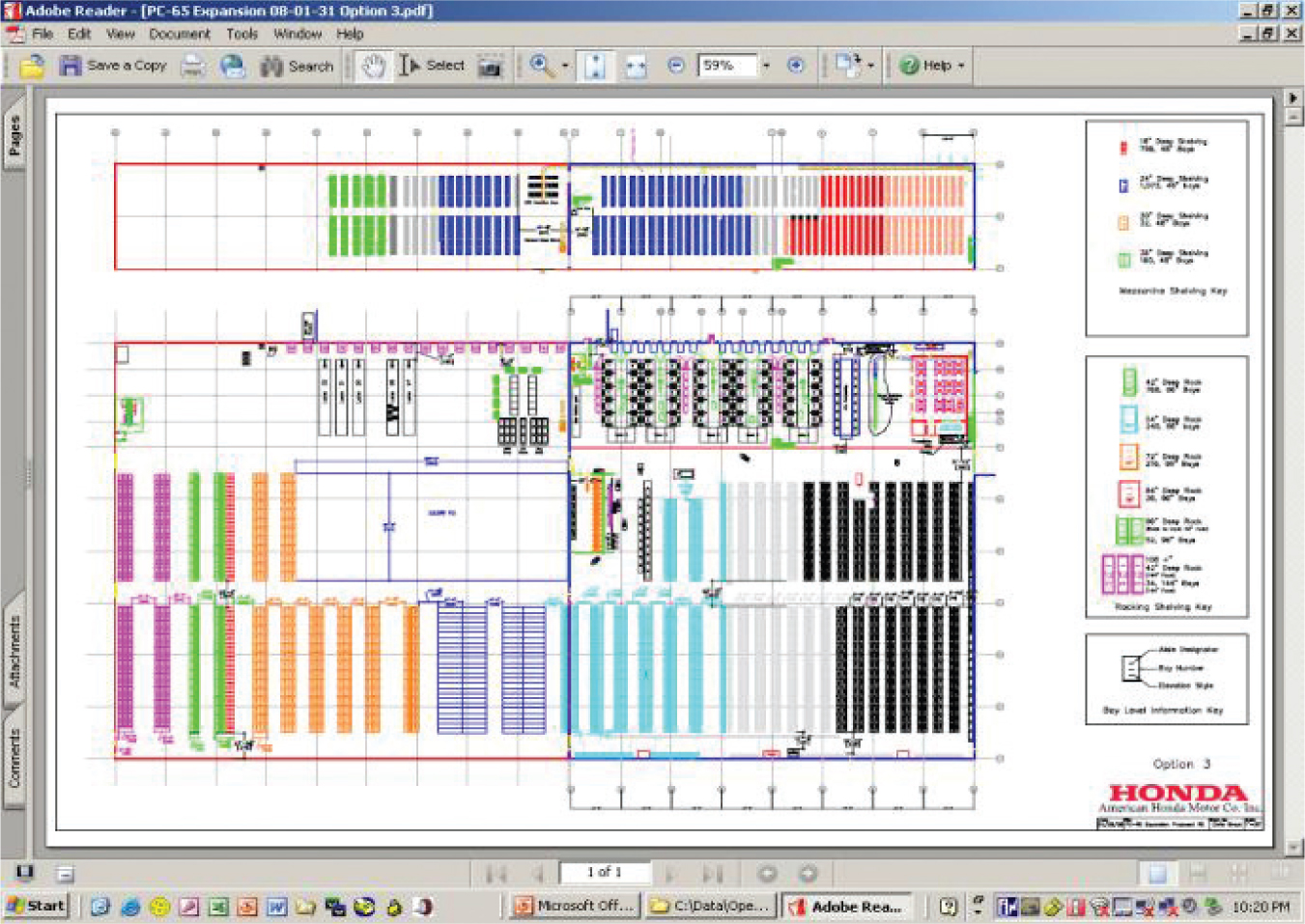
Figure 9.9 Typical U-shaped flow pattern.
9.3 Material Flow Planning
U-shaped, straight-through, modular-spine, and multi-story flow paths work in isolation or in conjunction with one another to form the large majority of warehouse flow paths.
U-Shaped Flow
An example U-shaped warehouse flow design is shown in Figure 9.9. Products flow in at receiving and move to receiving staging, pallet storage, case picking, broken-case picking, order assembly, and shipping.
A U-shaped flow design has a number of advantages over other flow designs, including the following:
![]() It yields high utilization of dock resources (i.e., dock doors, dock equipment, dock space, dock operators, and dock supervisors) because the receiving and shipping processes can share dock doors.
It yields high utilization of dock resources (i.e., dock doors, dock equipment, dock space, dock operators, and dock supervisors) because the receiving and shipping processes can share dock doors.
![]() It facilitates cross-docking because the receiving and shipping docks are adjacent to one another.
It facilitates cross-docking because the receiving and shipping docks are adjacent to one another.
![]() It yields high lift-truck utilization because put-away and retrieval trips are easily combined and because the storage locations closest to the receiving and shipping docks are natural locations to house fast-moving items.
It yields high lift-truck utilization because put-away and retrieval trips are easily combined and because the storage locations closest to the receiving and shipping docks are natural locations to house fast-moving items.
![]() It allows expansion opportunities in three directions.
It allows expansion opportunities in three directions.
![]() It provides excellent security because a single side of the building is used for entry and exit.
It provides excellent security because a single side of the building is used for entry and exit.
With these inherent advantages, U-shaped flow design is the benchmark against which all other flow designs should be compared.
Straight-Through Flow
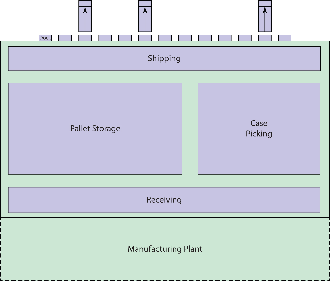
Examples of straight-through flow design are illustrated in Figures 9.10 and 9.11. The straight-through configuration lends itself to warehouse operations that are attached to factories (with receipts arriving directly from production lines) to pure cross-docking facilities (sometimes referred to as flow-through facilities), or to operations in which the peak receiving and shipping times coincide. The major disadvantage is that the design does not lend itself to ABC storage and dual-command trips.
Figure 9.10 Straight-through flow design.
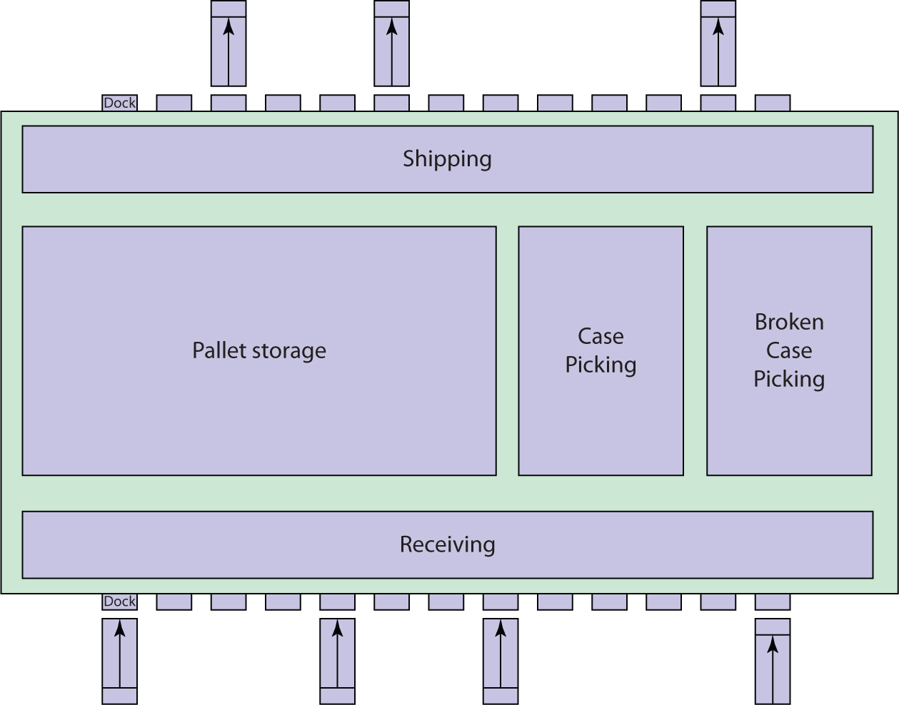
Figure 9.11 Straight-through flow design with an attached manufacturing plant.
Modular-Spine Design
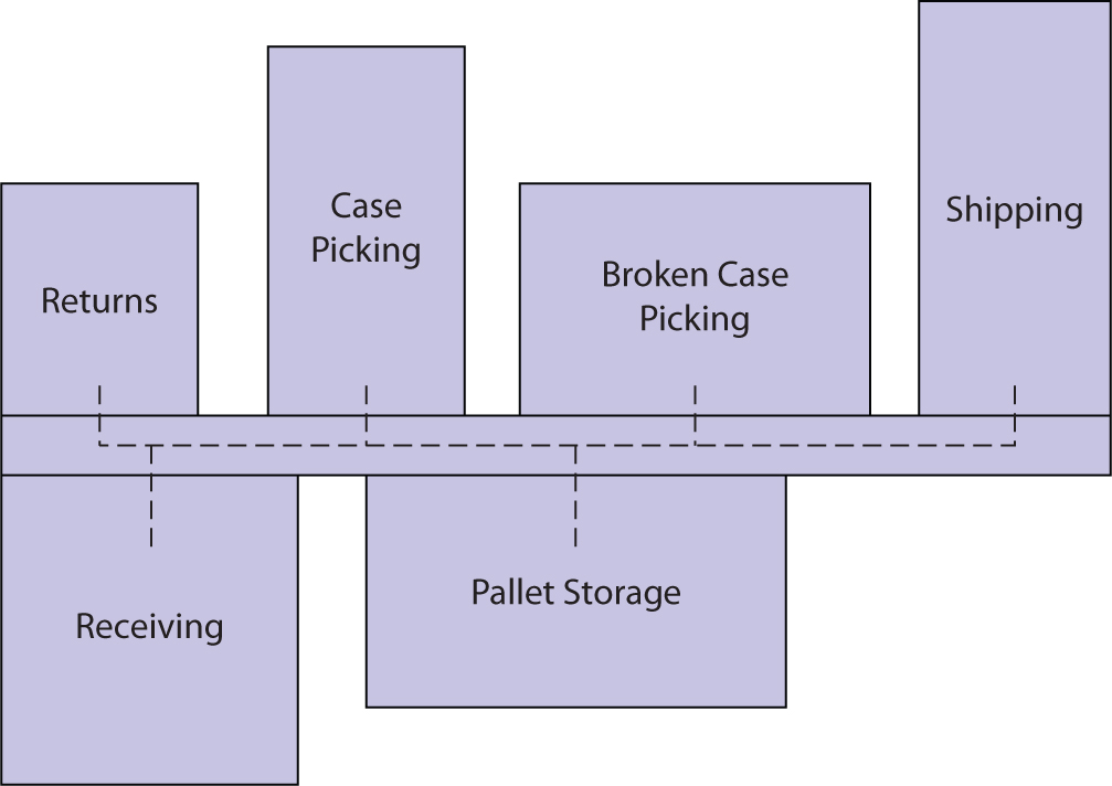
A modular-spine design (Figure 9.12) uses a large material-handling spine to connect independent buildings dedicated to specific warehouse activities in large-scale warehousing and distribution environments. Examples of stand-alone warehouse buildings include rack-supported buildings for a unit-load automated storage and retrieval system (ASRS); an air-conditioned building for customizing operations such as monogramming, pricing, and marking; a building dedicated to returns processing; and a shipping building equipped with high-speed sorting equipment.
Figure 9.12 A modular-spine flow design.
Multistory Layouts
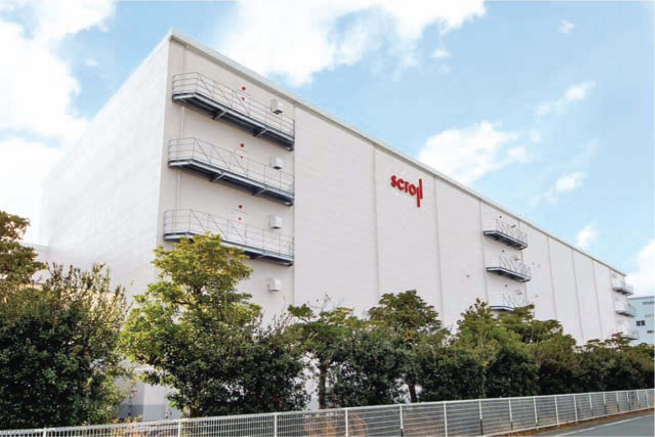
Multistory distribution buildings (Figure 9.13) are necessary when land is extremely scarce. Multistory distribution centers are common in Japan and some parts of Europe. They are the least desirable of the flow-path alternatives because of the material-handling difficulties and bottlenecks encountered in moving merchandise between floors.
Figure 9.13 Recently completed multistory distribution center design for one of Japan’s top consumer-direct apparel companies, Scroll, located just outside of Nagoya.
9.4 Bay Matching
One of the major reasons for low building cube utilization in warehouse facilities is that processes that can be executed in low-bay space—receiving, broken-case picking, customization, returns processing, and so on—are often executed in high-bay space. High-bay space can be mezzanined to accommodate multiple low-bay processes in the same floor space. The key design principle is to assign processes with high storage requirements to high-bay space and labor-intensive processes to low-bay space.
9.5 Material Handling Equipment
In addition to the material handling moves within activities, there are major moves between warehouse activities. The two basic categories of interactivity material handling equipment are industrial vehicles and conveyors.
Industrial Vehicles
Lift trucks, automated guided vehicles, sorting transfer cars, and automated storage/retrieval vehicles are industrial vehicles used to move goods between the major activities in a distribution center (Figure 9.14 and Figure 9.15).
Figure 9.14 Automated guided vehicle systems are an increasingly popular means of transporting goods between warehouse activities.
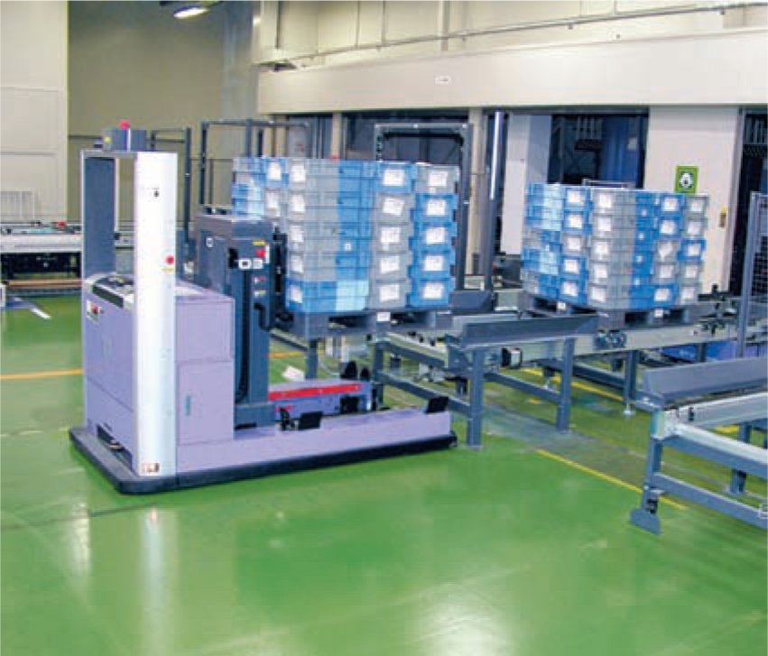
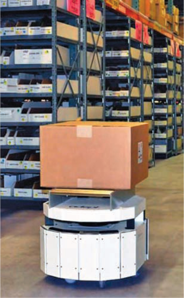
Figure 9.15 Small-load autonomous mobile transporter (Adept).
Conveyor Systems
Overhead power and free conveyors, car-on-track conveyors, pallet conveyors, and tow-line conveyors are all used to move material between the major functional areas of a warehouse (Figures 9.16 through 9.19).
Figure 9.16 Powered pallet roller conveyor is the benchmark for interactivity distribution center conveyor movements.
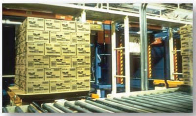
Figure 9.17 Overhead monorails provide quiet, high-speed transport between warehouse activities.
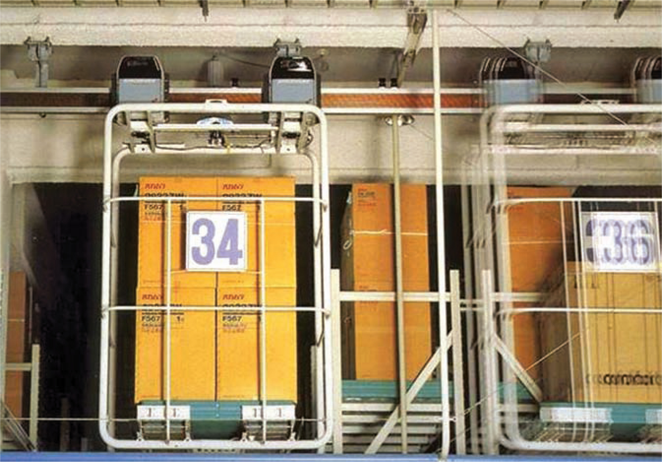
Figure 9.18 Suntory uses cart-on-track conveyors to rapidly move full pallets throughout its distribution center.
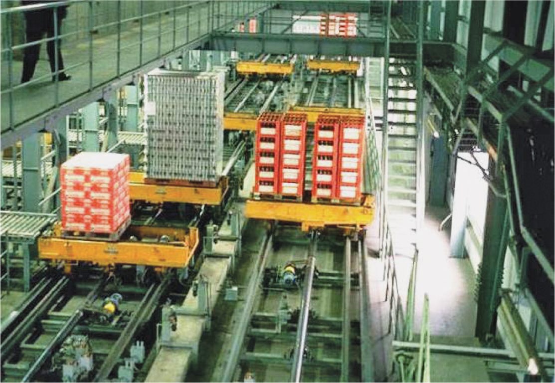
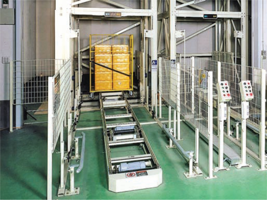
Figure 9.19 Pallet conveyors feeding vertical transport systems are a common means of interactivity movement in multistory warehouses.
9.6 Maximize Space Efficiencies
Floor-space requirements in a given area and in the overall layout can and should be reduced by
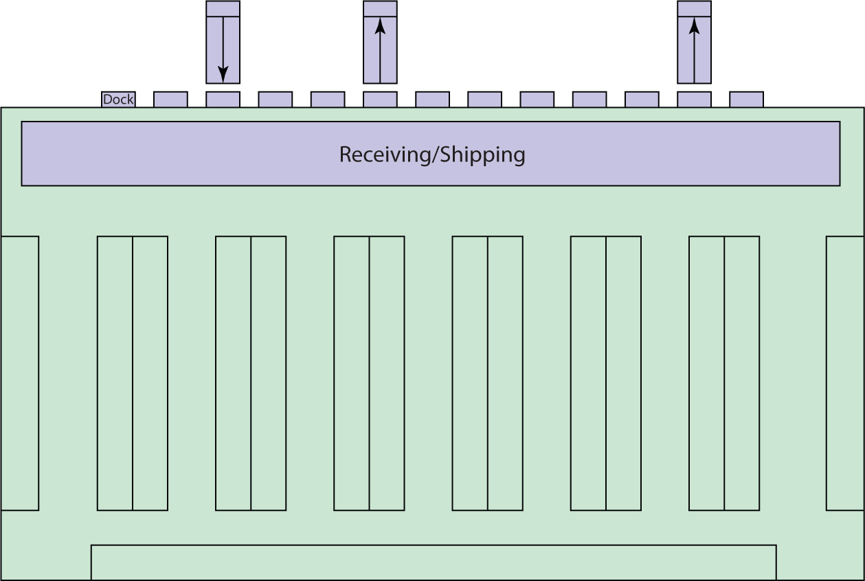
![]() Running storage lanes and racking parallel to the long axis (Figure 9.20) vs the short axis (Figure 9.21) of the building
Running storage lanes and racking parallel to the long axis (Figure 9.20) vs the short axis (Figure 9.21) of the building
Figure 9.20 Running storage lanes along the long axis of the building yields high floor-space utilization.
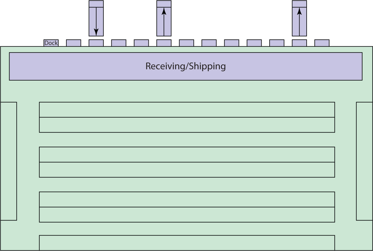
Figure 9.21 Running storage lanes along the short axis of the building yields good location access.
![]() Running storage lanes and racking along interior walls (Figure 9.22)
Running storage lanes and racking along interior walls (Figure 9.22)
Figure 9.22 Storage along interior walls helps maximize space utilization.
![]() Implementing a random storage location policy in large storage areas
Implementing a random storage location policy in large storage areas
![]() Using over-aisle (Figure 9.23), over-dock (Figure 9.24), and over-line storage (Figure 9.25)
Using over-aisle (Figure 9.23), over-dock (Figure 9.24), and over-line storage (Figure 9.25)
Figure 9.23 Over-aisle storage.
Figure 9.24 Over-dock storage in a telecommunications warehouse.
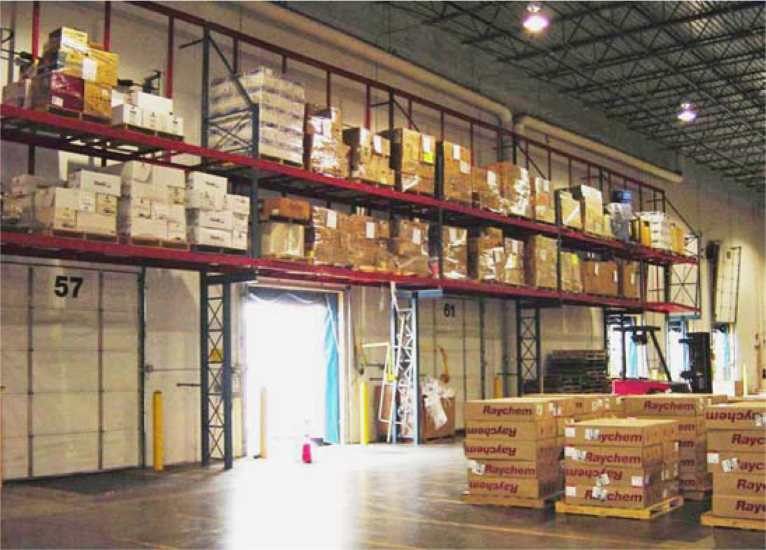
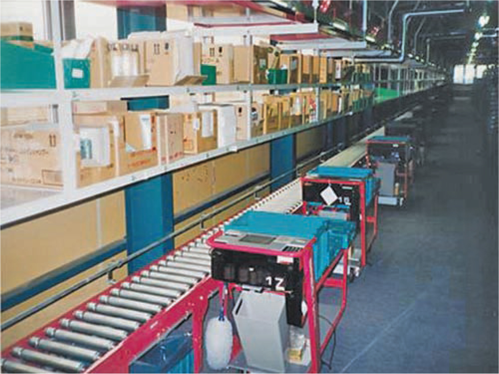
Figure 9.25 Storage capacity created over conveyor lines in a Japanese wholesale distribution center.
![]() Burying building columns in storage racks (Figure 9.26)
Burying building columns in storage racks (Figure 9.26)
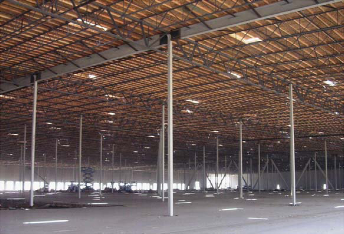
Figure 9.26 Column placement is one of the critical design features in warehouse layout. In this design for Payless Shoes, we made sure to bury columns within the confines of required material handling structures to maximize floor space utilization.
9.7 Expansion/Contraction Planning
The only thing we know about tomorrow is that it will be different from today. In a warehouse, different may mean larger or smaller, faster or slower, more or less variety, taller or shorter, more or fewer people, more or less technology, and so on. To accommodate the rapid pace of change, a carefully configured warehouse layout includes expansion and contraction plans for each activity in the warehouse and for the warehouse as a whole.