CHAPTER TEN
WAREHOUSE COMMUNICATION SYSTEMS
10.1 Automatic Identification Systems
10.2 Automatic Communication Systems
10.3 System Selection and Justification
Each year we conduct a survey to determine industry priorities for warehouse management systems functionality. Nearly every year the top three priorities are (1) paperless communication, (2) live inventory, and (3) productivity tracking.
Why is paperless the top priority? Many of the hurdles on the race to world-class warehousing are related to paper and paper handling. First, it is easy to lose paper. I do it every day. Second, you have to read paper. Reading warehouse documents usually requires searching through a maze of information for just a single line that matters for the transaction at hand. Transpositions creep in. Third, you have to write on paper. Again, it is easy to transpose something. Fourth, things on paper cannot be communicated in real time. As a result, errors in inventory levels, product locations, task status, and/or order status are not known with real-time reliability, making it difficult or impossible to implement cross-docking and transaction interleaving. Fifth, paper is expensive to print, handle and file. Sixth, it is easy to damage and smudge paper. Paperless warehousing and world-class warehousing go hand in hand!
Digital and real-time warehousing requires an enabling set of devices and technologies. These devices are the data-collection and communication devices forming the backbone of integrated logistics information systems. Because the list of devices grows daily, it is impossible to present a perfectly current picture of the state of paperless warehouse technologies in book form. Logistics industry trade shows and related websites are the best and perhaps only continually updated presentation of the current state of paperless warehousing technology.
Although the menagerie of devices is changing and being upgraded rapidly, the general categories of technologies have remained fairly stable. First, to support paperless warehousing, we need a way to automatically identify warehousing objects (i.e., containers, documents, vehicles, and locations). We call those means automatic identification technologies. They include optical characters and readers, bar codes and bar code readers, radio frequency (RF) tags and readers, smart cards and smart card readers, and vision systems. Second, we need a means to communicate information to warehouse operators. Those means we call automatic communication technologies. They include RF data communications, digitized voice, virtual displays, and task-by-light systems.
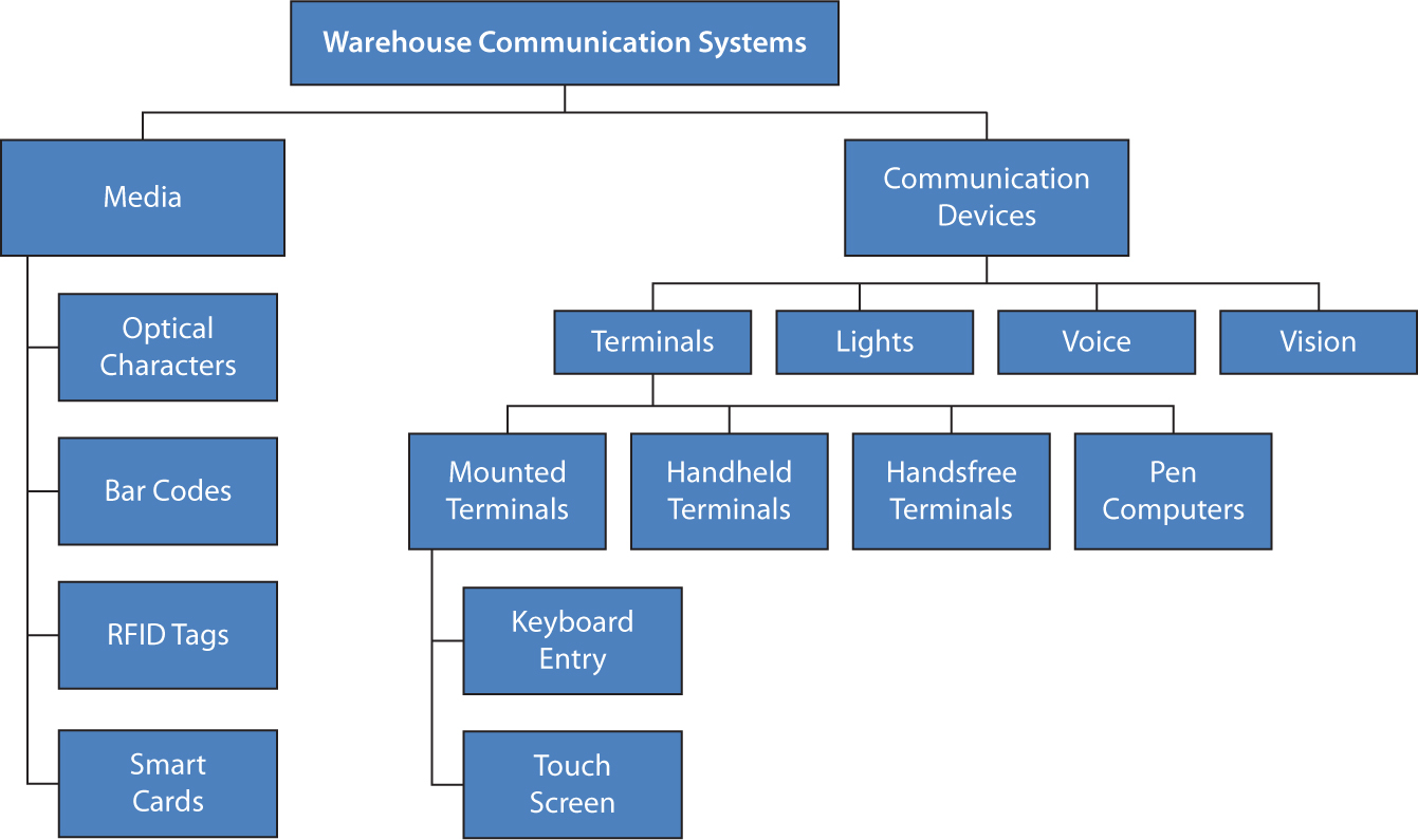
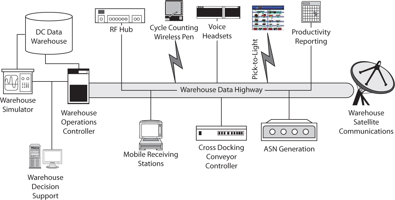
Paperless warehousing communication devices are the interface between warehouse operators and warehouse management systems. The decisions made in those brief and myriad interactions govern the productivity, accuracy, and speed of the entire warehouse. Hence the design and selection of these devices and systems are critical to the success of the overall operation (Figure 10.1).
Figure 10.1 RightComms™ taxonomy of warehouse communication systems.
10.1 Automatic Identification Systems
Four primary automatic identification systems are used in warehousing—optical characters and readers, bar codes and bar code readers, RF identification (RFID) tags and readers, and smart cards and smart card readers.
Optical Characters
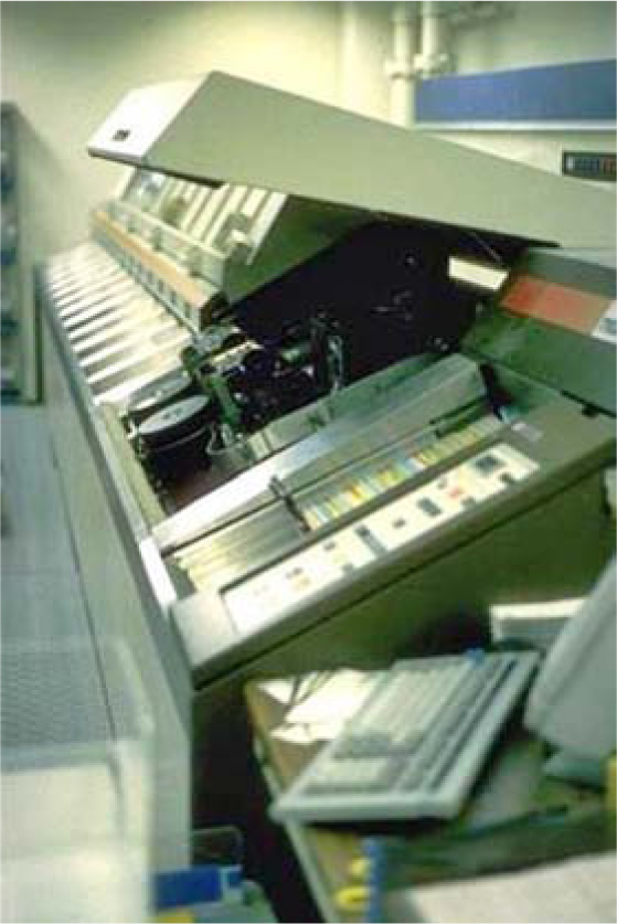
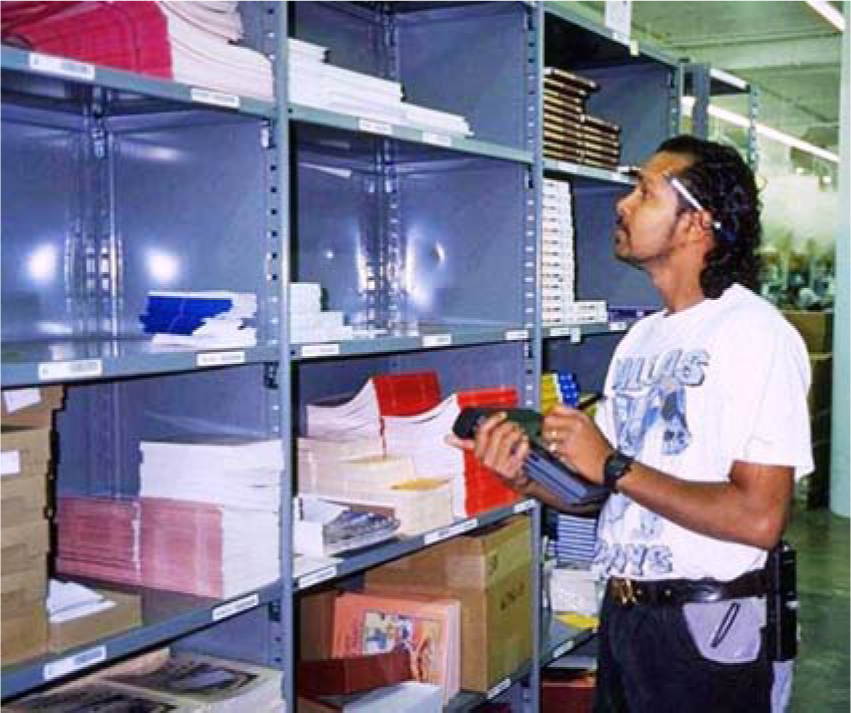
Although rare, optical characters (Figure 10.2) are still employed in some warehouse operations. Optical characters are readable by both humans and machines. The digits at the bottom of a bank check are the most common use of optical characters (Figure 10.2). Much like a bar code, an OCR label is read with a hand-held (Figure 10.3) or automated scanner (Figure 10.4). OCR systems operate at slower read rates than bar-code systems and are priced about the same. OCR systems are attractive when both human- and machine-readable capabilities are required.
Figure 10.2 Optical characters

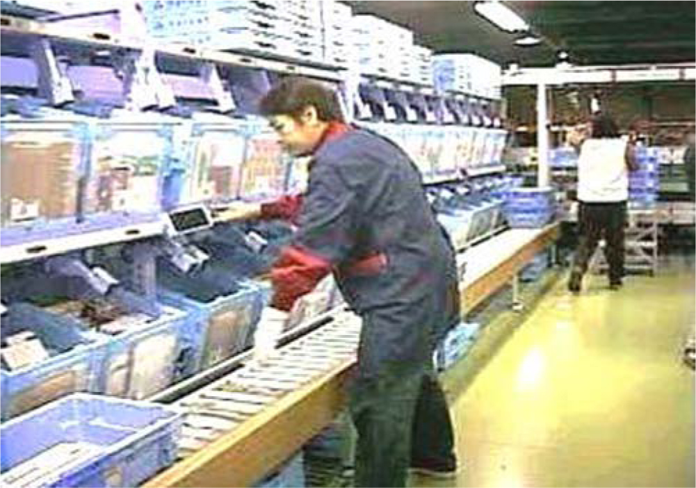
Figure 10.3 Sorter induction operator scanning optical characters in a large Japanese book distributor.
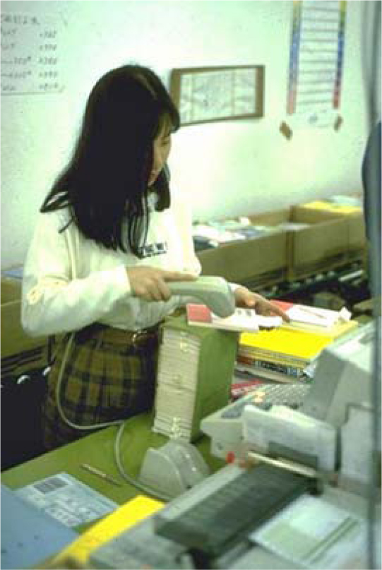
Figure 10.4 OCR reader scanning optical characters in a large Japanese book distributor.
Bar Codes and Bar-Code Scanners
A bar-code system includes a bar-code symbology to encode and decode alphanumeric characters to/from dark and light spaces, bar-code readers to interpret the bar-code symbology, and bar-code printers to reliably and accurately print bar codes on labels, cartons, and/or documents.
Bar-Code Symbologies A bar code is a series rectangles and intervening spaces. The structure of unique rectangle/space patterns represents various alphanumeric characters. The same pattern may represent different alphanumeric characters in different symbologies.
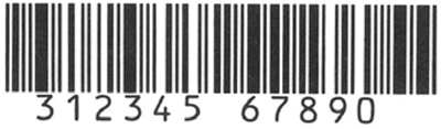
The codes themselves fall into one of five major groupings—one-dimensional (1D) linear bar codes, stacked linear bar codes, two-dimensional (2D) matrix codes, postal codes, and Quick Response (QR) codes. Linear 1D bar codes are the most common type of bar code. All the information contained within the code is organized horizontally and read from left to right by the scanner (Figure 10.5).
Figure 10.5 Linear 1D bar code.
As the name implies, stacked linear bar codes are simply 1D linear bar codes stacked on top of one another. An example is shown in Figure 10.7. The main advantage over simple 1D codes is the ability to encapsulate a large amount of alphanumeric data in a small footprint.
Two-dimensional bar codes, sometimes referred to as high-density codes, are overlapping linear bar codes, one horizontal and the other vertical, in the same field. These codes permit the automatic encoding of nearly a printed page’s worth of text in a square inch of page space. Examples include Code 49, Code 16k, PDF 417, Code One, Datamatrix, UPS’s Maxicode, and the currently popular QR code (Figure 10.10). It is a type of 2D or matrix code developed in Japan and now in popular use because of its information density and ability to encode URLs.
Figure 10.6 Linear bar codes in use at Boots Pharmacy (London, England).
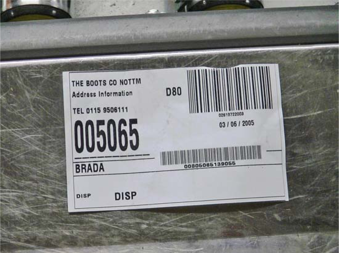
Figure 10.7 Stacked linear bar code
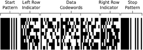
Figure 10.8 Linear bar codes in use for product identification and sorter induction at L.L. Bean.
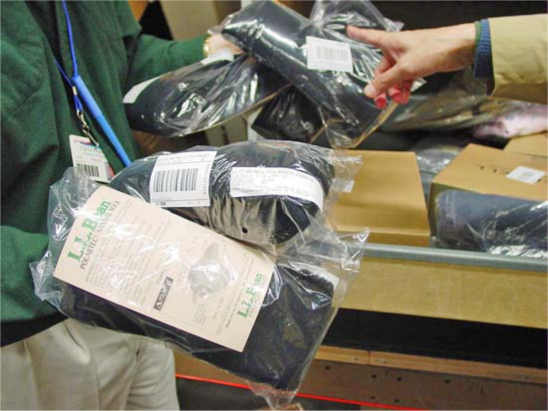
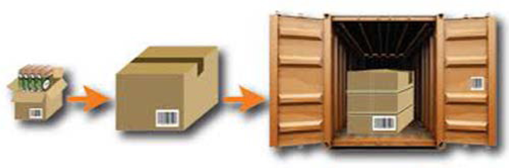
Figure 10.9 Product with identifying code and tag unitized in a case with identifying code and tag, palletized onto pallets with identifying code and tag, and containerized in container with code and tag.

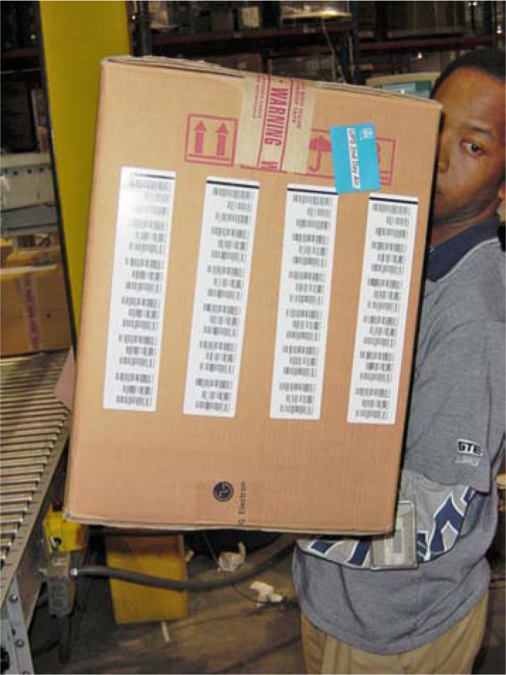
Bar codes can be used effectively to identify products, containers, locations, operators, equipment, and documents. However, one bar-code “gotcha” is the tendency to get caught up in bar coding for the sake of bar coding. If there is too much bar coding and too much bar-code scanning, the costs and time to print and scan all the codes can quickly negate potential productivity and accuracy benefits (Figure 10.11).
Figure 10.11 An over labeled and over coded carton.
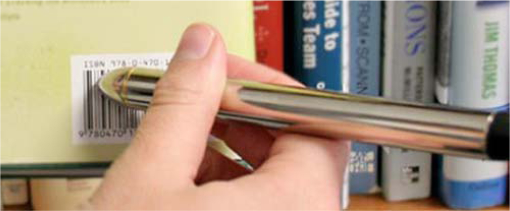
Bar-Code Readers Bar codes are read by contact and noncontact scanners. Contact scanners (Figure 10.12) must touch the bar code. They can be portable or stationary and typically come in the form of a wand or a light pen. The wand/pen is manually passed across the bar code. The scanner emits either white or infrared light from the wand/pen tip and reads the light pattern that is reflected from the bar code. This information is stored in solid-state memory for subsequent transmission to a computer. Contact scanners are excellent substitutes for keyboard or manual data entry. Alphanumeric information is processed at a rate of up to 4 to 24 inches per second, and the error rate for a basic scanner connected to its decoder is 1 in 1 million reads.
Figure 10.12 Pen (or wand) bar-code scanner.
Non-contact scanners (Figures 10.13 through 10.18) may be hand held or mounted and include fixed-beam scanners, moving-beam scanners, and charge-coupled-device (CCD) scanners. Non contact scanners employ fixed-beam, moving beam, video camera, or raster scanning technology to take from one to several hundred looks at the code as it passes. Most bar code scanners read codes bidirectionally by virtue of sophisticated decoding electronics that distinguish the unique start/stop codes peculiar to each symbology. Further, most scanner suppliers provide equipment with an auto-discrimination feature that permits recognition, reading, and verification of multiple symbol formats with no internal or external adjustments. Finally, suppliers have introduced omnidirectional scanners for industrial applications that are capable of reading bar codes passing through a large view field at high speeds regardless of the orientation of the bar code. Omni-directional scanners are commonly used in high-speed sorting systems.
Figure 10.13 Hand-held bar-code scanner.
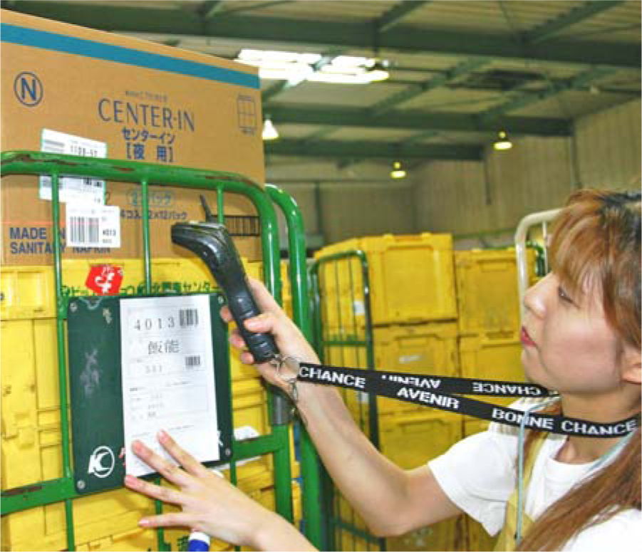
Figure 10.14 Long-distance hand-held bar-code scanner.
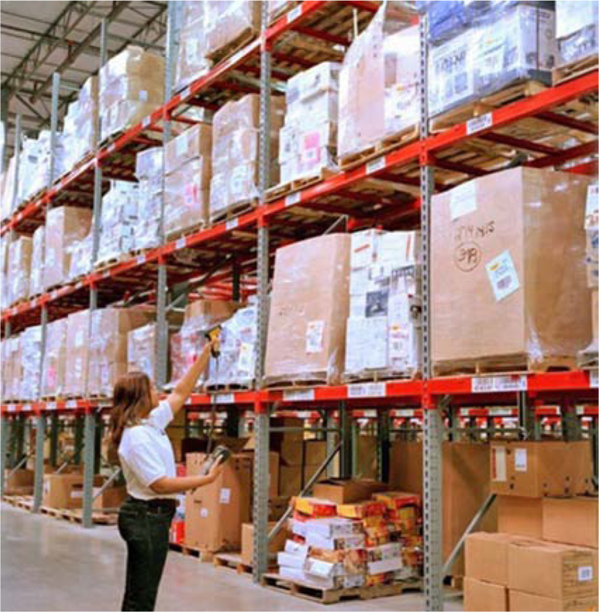
Figure 10.15 Hands-free ring scanner.
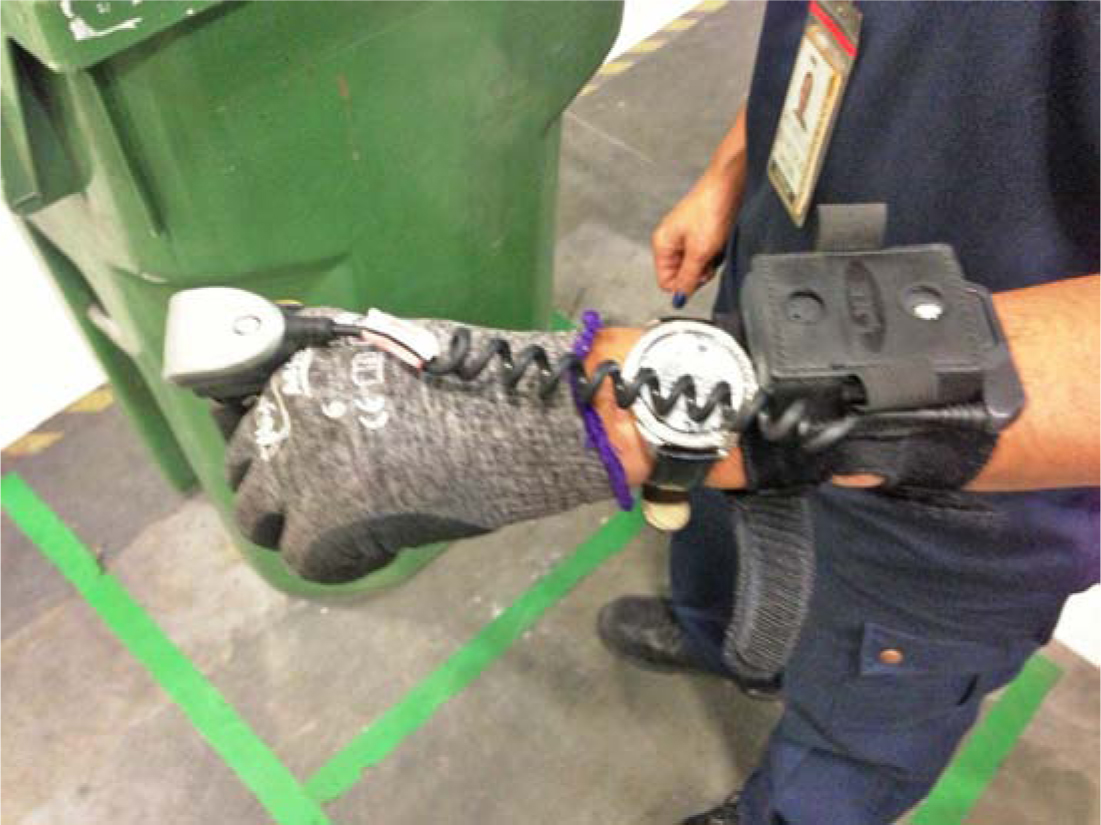
Figure 10.16 In-line bar-code scanner.
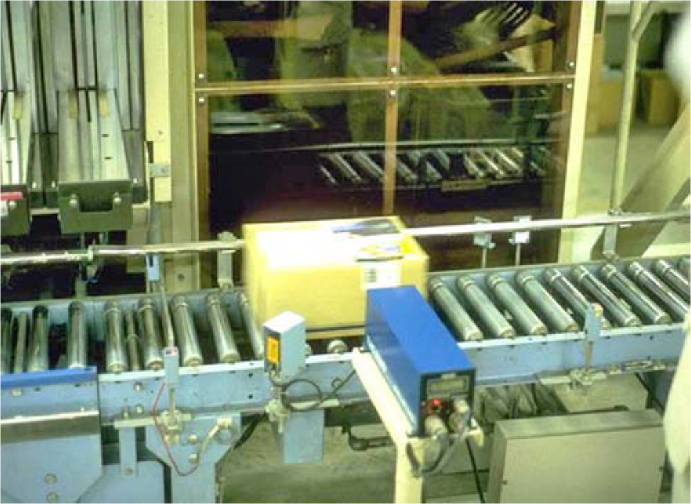
Figure 10.17 Omnidirectional bar-code scanning.
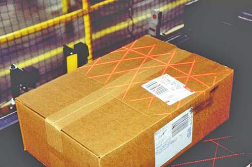
Figure 10.18 Omnidirectional bar-code scanner for tilt-tray sorting.
Radio Frequency Tags
Radio frequency identification (RFID) tags (Figures 10.19 through 10.24) encode data on a chip that is encased in a tag. When a tag is within range of a special antenna, the chip is decoded and read by a tag reader. RFID tags can be programmable or permanently coded. Some tags are permanently coded and can be read only within a small range.
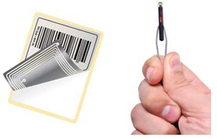
Figure 10.20 Tagged pieces in tagged cartons on a tagged pallet (Lindsay and Reade).
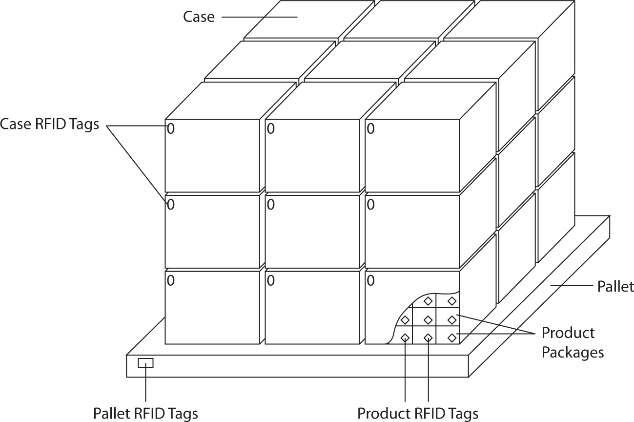
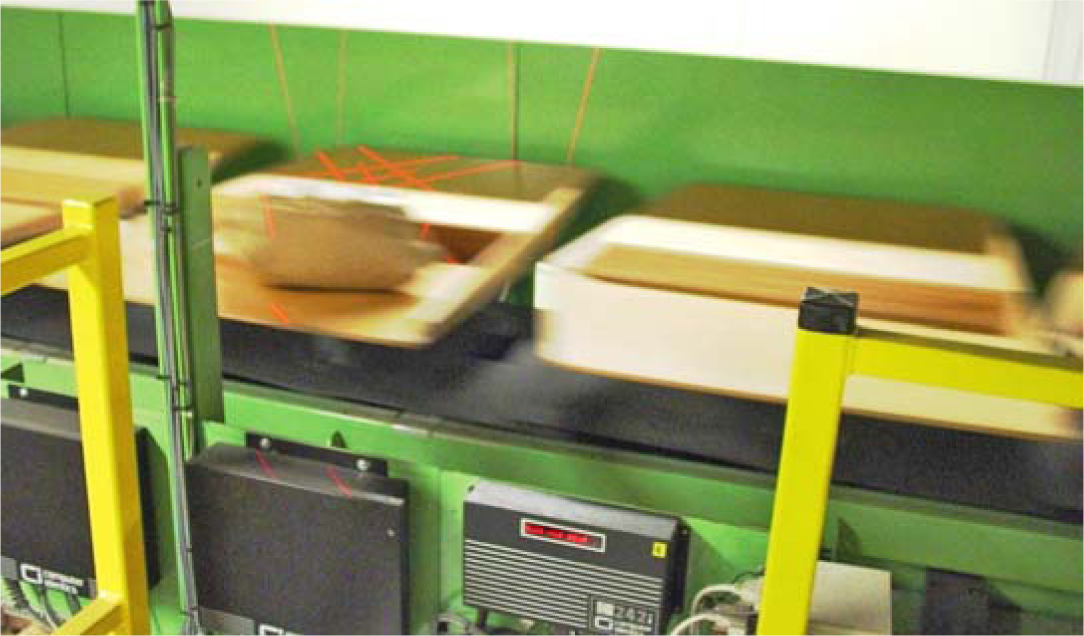
Figure 10.21 Inbound pallet RFID tag reader at a Marks & Spencer distribution center (London, England).
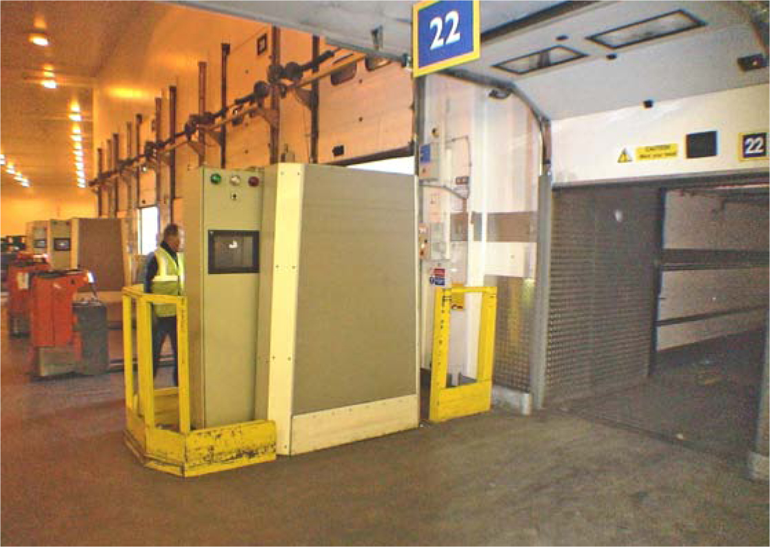
Figure 10.22 RFID tags for tote tracking at Marks & Spencer.
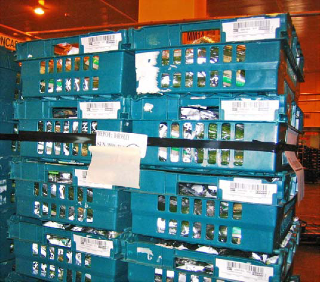
Figure 10.23 Pallet RFID tag reader at Metro (Munich, Germany).
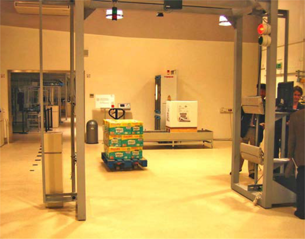
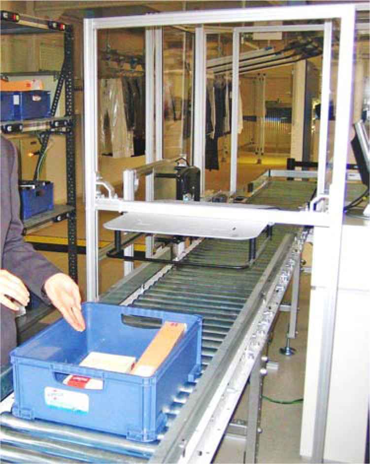
Figure 10.24 RFID tag reader reading the contents of outbound totes.
RFID tags are often used for permanent identification of a container, where printed codes may deteriorate and become illegible.
Magnetic Stripes and Optical Cards
Magnetic stripes commonly appear on the back of credit or bank cards. The magnetic stripe is readable through dirt or grease. Data contained on the stripe can be changed. The stripe must be read by contact, thus eliminating high-speed sorting applications.
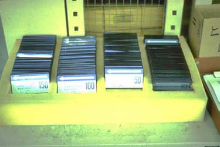
Smart cards are now used in logistics to capture information ranging from employee identification, to the contents of a trailer load of material (Figure 10.25), to the composition of an order-picking tour (Figure 10.26). For example, at a large cosmetics distribution center, order-picking tours are downloaded onto smart cards. The smart cards, are inserted into a smart card reader built into each order picking cart. The picking tour is illuminated on an electronic map of the warehouse appearing on the front of the cart.
Figure 10.25 Optical memory card used in automated truck manifesting and RFID tag used in container identification.
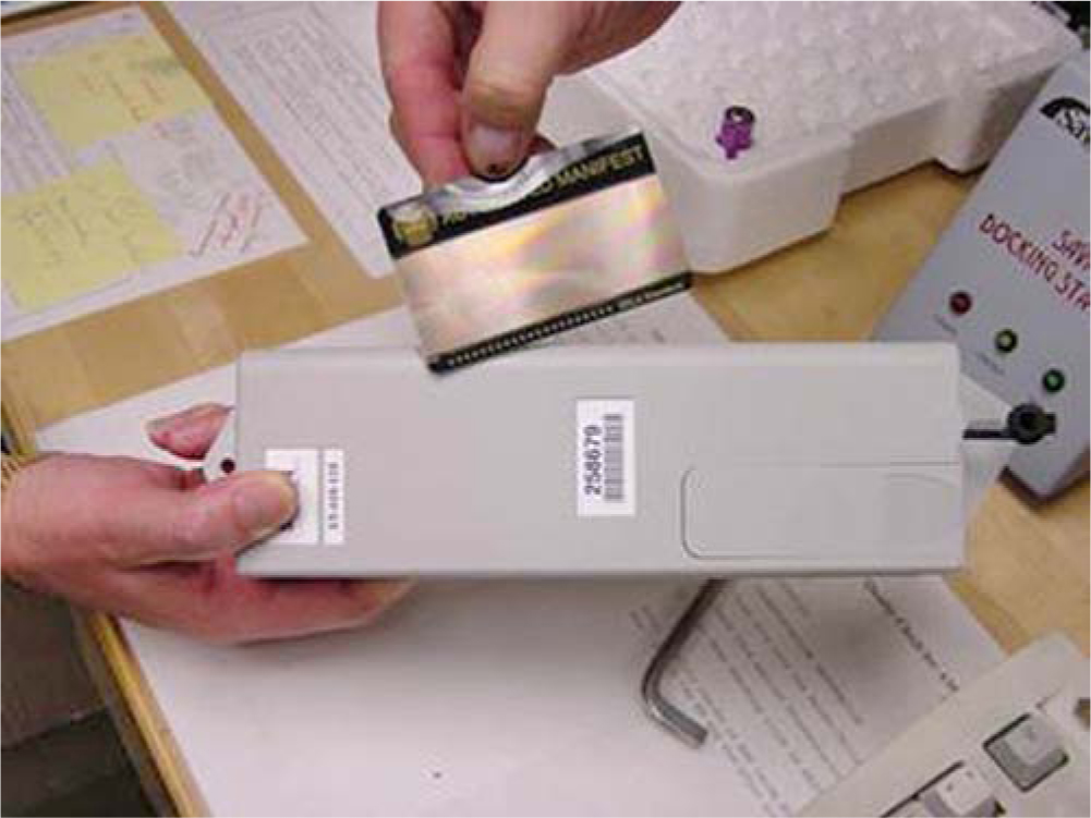
Figure 10.26 Smart cards used in an order-picking application at Shiseido’s Tokyo distribution center. Each card’s magnetic stripe holds a picking tour. The smart cards are read by a smart card reader attached to each intelligent picking cart.
10.2 Automatic Communication Systems
The basic information required by operators to complete a warehousing task includes the identification and quantity of the material to move, the origin, and the destination. There are a variety of means of communicating this basic information, including RF data communications, lights, digitized voice, and virtual displays.
RF Data Communications
Hand-held, lift-truck-mounted, and hands-free RF data terminals (RDTs) are reliable tools for inventory management. RDTs (Figures 10.27 through 10.30) incorporate a multicharacter display, full keyboard, and special function keys. They communicate and receive messages on a prescribed frequency via strategically located antennas and a host computer-interface unit. Improved inventory accuracy and warehouse resource utilization are most often cited in financial justifications for RDTs. The increasing availability of software packages that permit RDT linkage to existing plant or warehouse control systems greatly simplifies their implementation.
Figure 10.27 Vehicle-mounted RDT with touch-screen capability at Happinet’s Tokyo distribution center.
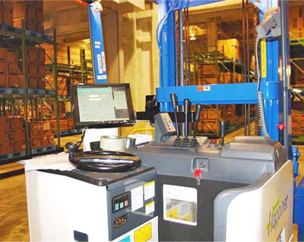
Figure 10.28 Vehicle-mounted RDT.
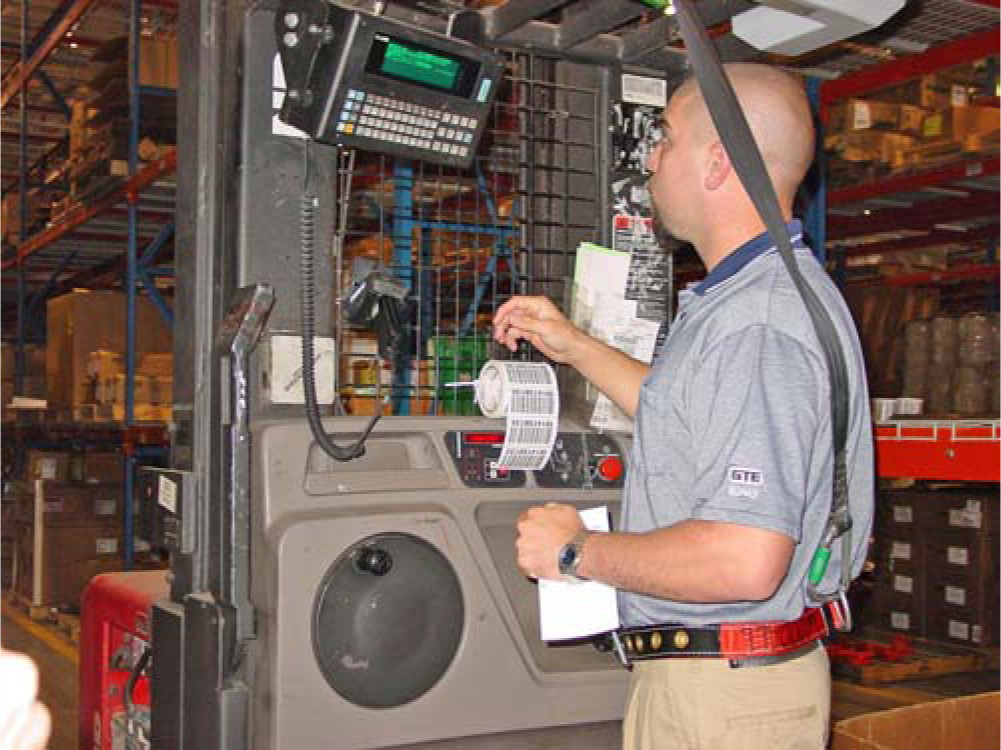
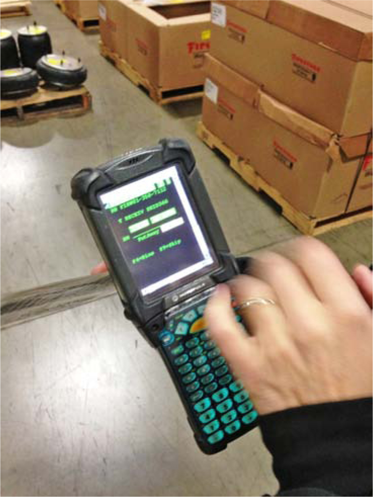
Figure 10.30 Cycle counting via RDT with pen computing.
Lights and Displays
Task lit operations (Figures 10.31 through 10.38) use indicator lights and lighted alphanumeric displays to direct warehouse operators in order picking, put-away, and/or sorting. The most popular use is in broken-case picking from flow racks, shelving, and/or carousels. In flow racks or bin shelving, a light display is placed at the front of each pick location (in the place of a location label). The light is illuminated if a pick is required from that location. The number of units to pick appears on the same display or on a display at the top of the flow rack or shelving bay. Typical picking rates are in the range of 300 to 600 lines per person-hour, and accuracy is around 99.97 percent.
Figure 10.31 This pick-to-light system at Bertelsmann’s Gutersloh distribution center directs the operator to picking locations from the three pallet locations, with weigh checking to prohibit mispicks.
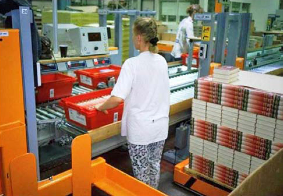
Figure 10.32 Pick-to-light with next task director display at Bertlesmann (Gutersloh, Germany).
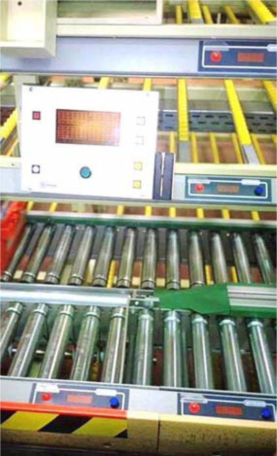
Figure 10.33 Pick-to-light in Lifeway’s National Logistics Center.
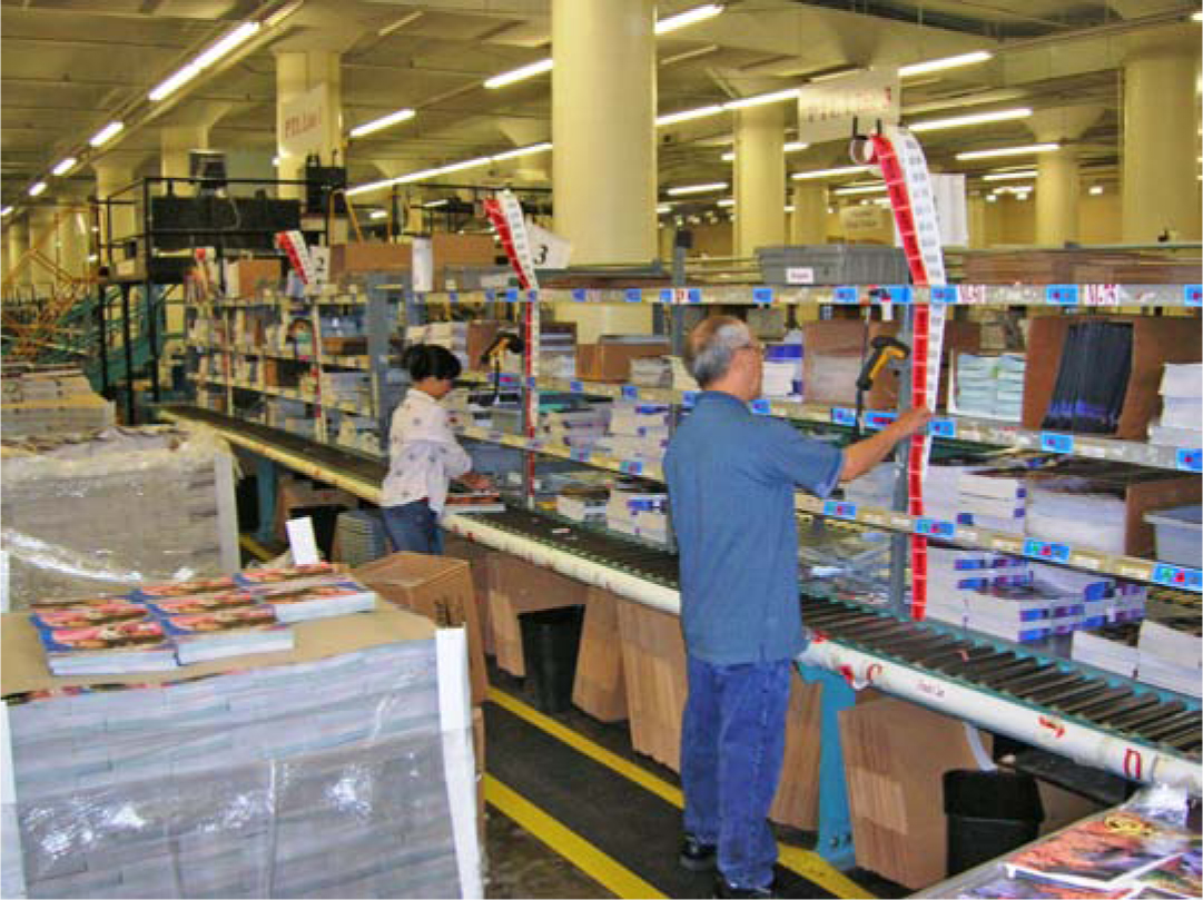
Figure 10.34 Pick-by-light flow rack.
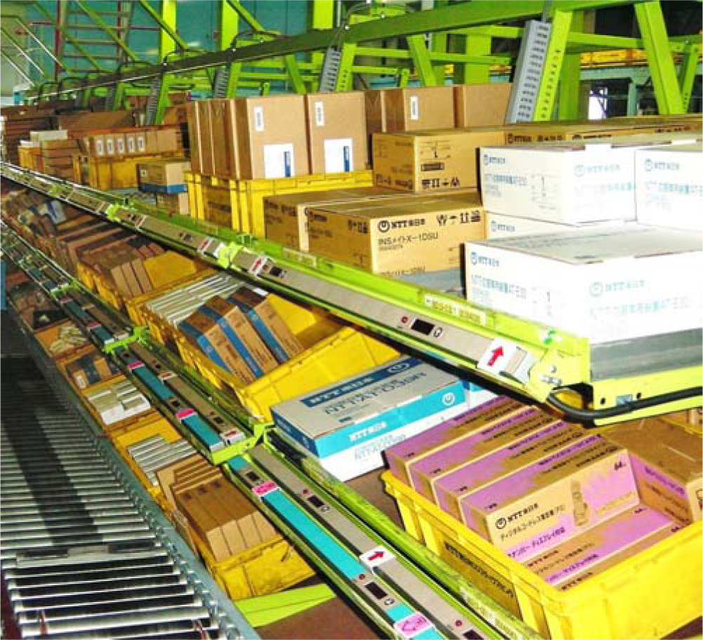
Figure 10.35 Pick-by-light carton flow rack in a Verizon warehouse.
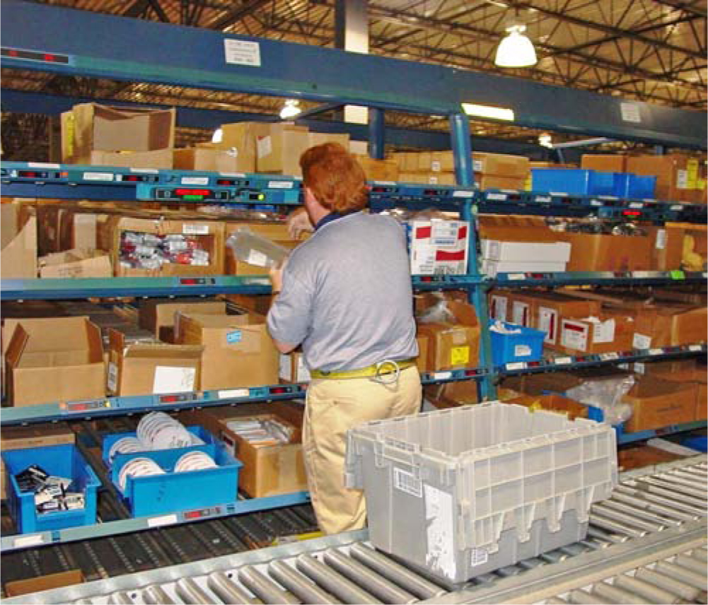
Figure 10.36 Pick-by-light carton flow-rack facings.
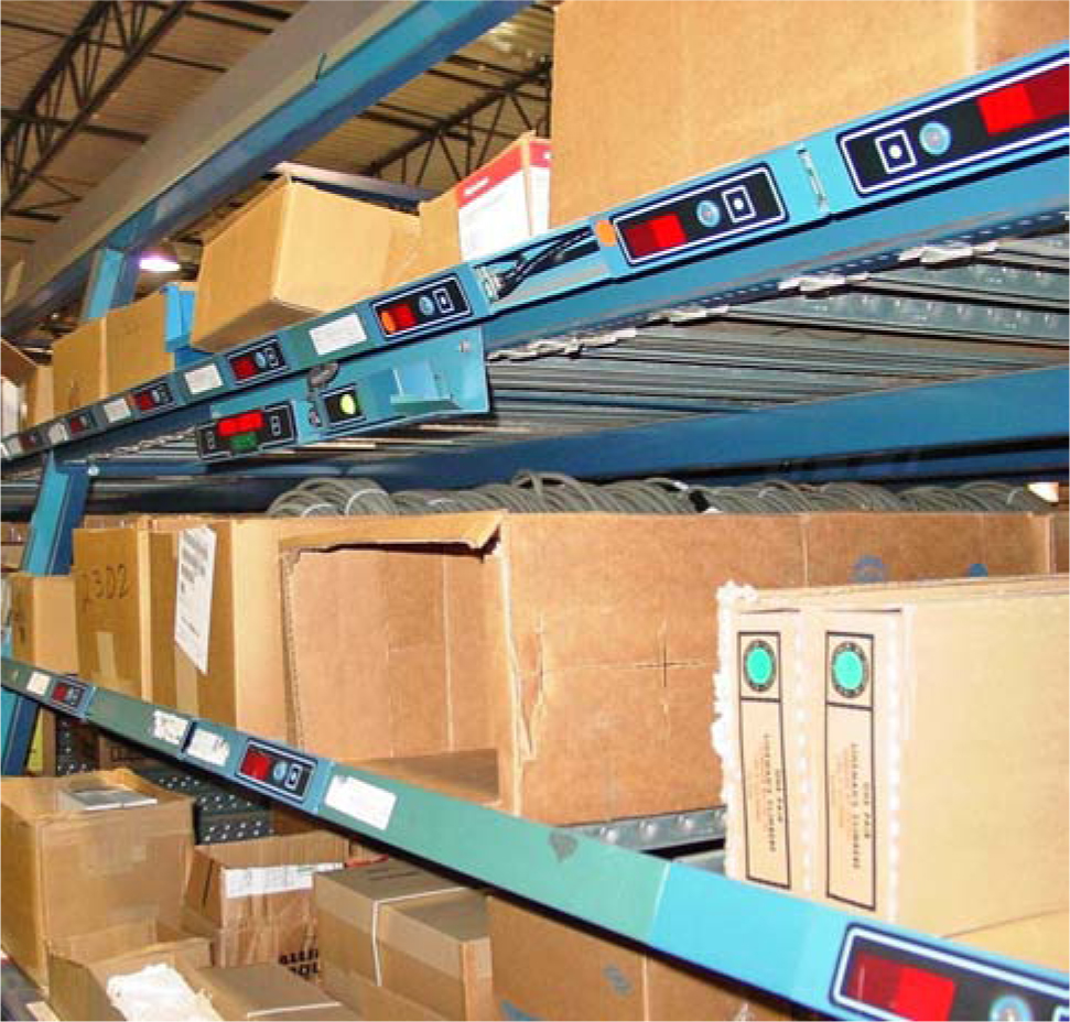
Figure 10.37 Pick-by-light carton flow-rack picking line for e-fulfillment at Nutrisystem’s Philadelphia distribution center. In addition to the pick-by-light system, notice the walking mats lining each side to reduce picking fatigue.
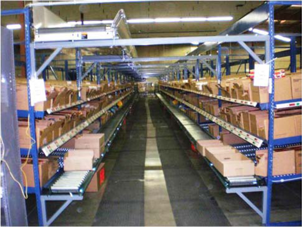
Figure 10.38 Pick-by-light and put-by-light to retail-store totes aided by next-pick and next-put director and motion detector to prevent mispicks and misputs (AT&C).
For carousels, a light tree is placed in front of each carousel. A light display appears on the tree to correspond to every picking level on the carousel. As a carrier is positioned in front of the order picker, the light display corresponding to the level to be picked from is illuminated. Lights also can be used to direct case picking and pallet storage and retrieval operations.
Voice Headsets
The use of synthesized voice is increasingly popular in warehouse operations. In mobile voice-based systems (Figures 10.39 through 10.41), warehouse operators wear a headset with an attached microphone. Via synthesized voice, the warehouse management system talks the operator through a series of transactions. For example, for a pallet put-away, the lift-truck operator hears a command to put away a particular pallet into a particular warehouse location. When the transaction is complete, the operator says, “Put-away complete” into the microphone. Then the system speaks the next transaction to the operator. If the operator forgets the transaction, he or she simply says, “Repeat transaction” and the system repeats the instruction.
Figure 10.39 Lift-truck operator with voice headset at Oxxo’s Monterrey distribution center.
Figure 10.40 Voice picking from a flow rack inside a cold room.
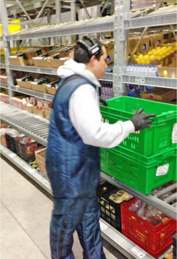
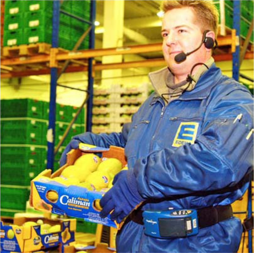
Figure 10.41 Voice headsets in case picking at Edeka, a large grocery retailer in the United Kingdom.
Voice-based systems permit operators to work with their hands free of documents or terminals and eyes free of reading the same. Another advantage is the ease with which the system is programmed. A simple Windows-based software package is used to construct conversations. To operate every area of the warehouse with a voice-based system would require conversations for receiving, put-away, restocking, order picking, and shipping. Once these conversations have been developed, the system is a warehouse management system unto itself. This approach can be an inexpensive way to achieve most of the functionality of a typical warehouse management system. A typical mobile voice-based system costs approximately the same as an RDT-based system.
Vision Systems
Vision system cameras take pictures of objects and codes and relay the images to a computer for interpretation. Vision systems “read” at moderate speeds with excellent accuracy. Obviously, vision systems do not require contact with the object or code. Vision systems are becoming less costly but are still relatively expensive.
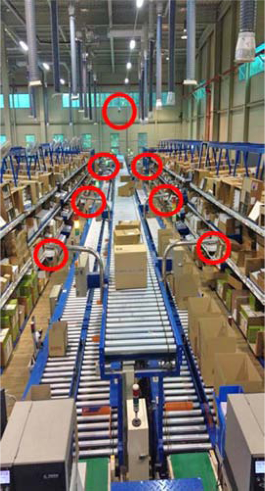
A large mail-order operator recently installed a vision system (Figure 10.42) at receiving. The system is located above a telescoping conveyor used to convey inbound cartons from a trailer into the warehouse. The system recognizes the inbound cartons that do not have bar codes, reads the product and vendor number on the carton, and directs a bar-code printer to print and apply the appropriate bar-code label. One of our large health and beauty clients uses vision systems throughout their picking area to automatically detect picking errors (Figure 10.43).
Figure 10.42 Vision system used to automate receiving inspection at Quelle’s logistics center in Leipzig, Germany.
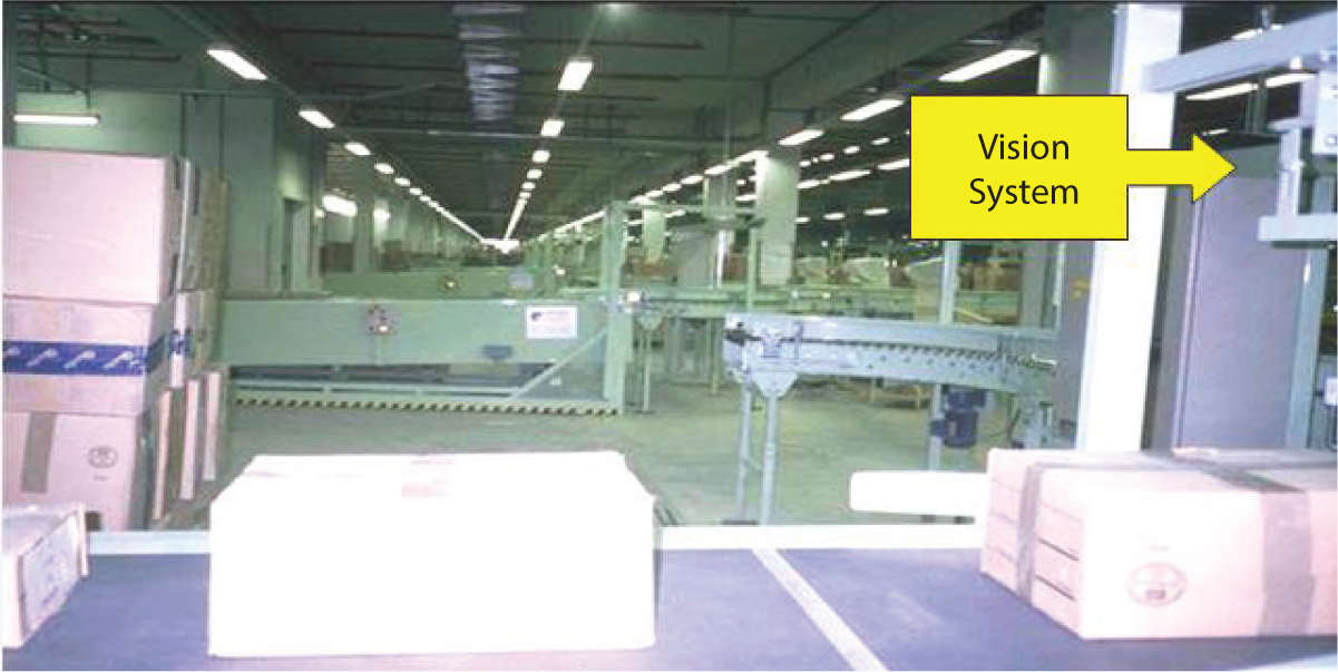
Figure 10.43 Automated picking and shipping inspection.
Virtual “Heads Up” Displays
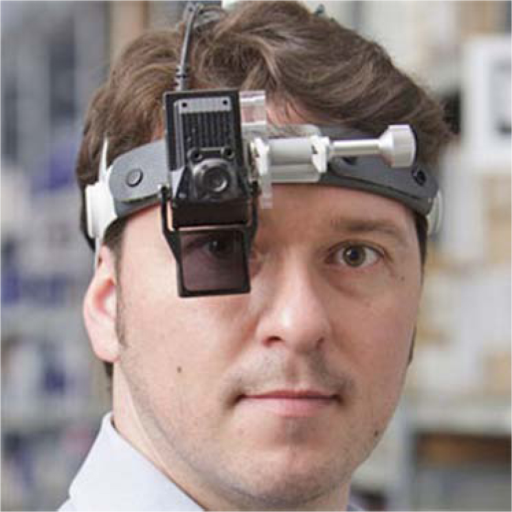
Virtual displays (Figure 10.44) present an operator with virtual overlays on the warehouse floor, to direct the operator through travel paths and/or to perform specific transactions on specific products. The displays also can be used to take an operator on a virtual tour of a three-dimensional (3D) warehouse layout. Virtual displays can be used in training warehouse operators in the full range of warehouse transactions.
Figure 10.44 Warehouse Data goggles (Knapp Logistics).
10.3 System Selection and Justification
The choice of a warehouse communication technology should be made considering the unique ergonomics for each warehouse activity. For example, picking is handling intensive and hence is best automated with hands-free communication technology, such as voice headsets or pick-to-light. Cycle counting or any kind of inspection is forms based and, lends itself to pen computing. The type, conditions, and frequency of the communications in each warehouse activity should guide the technology selection. An example warehouse communications plan developed for a recent client is shown in Figure 10.45.
Figure 10.45 RightComms warehouse communication systems design for a large retail distribution center.
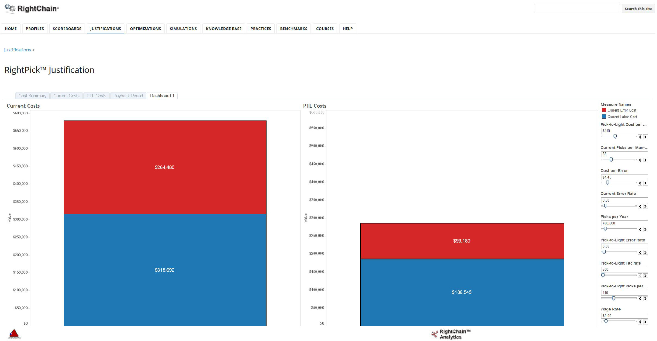
Another critical factor in the selection of warehouse communications technology is its return on investment (ROI). We take into consideration each technology’s impact on productivity, accuracy, investment, and reliability in developing an ROI for each warehouse activity. An example pick-to-light ROI is illustrated in Figure 10.46.
Figure 10.46 Warehouse communication system justification.