
In early computer graphics, graphic adapters were 2D (two-dimensional) only. Games created a frame by setting pixel colors in the graphics adapter's memory, then telling the graphics adapter to make the buffer active in a simple process called frame buffering. If a game was in 3D (three dimensions), it meant that the programmers wrote 3D-to-2D conversion methods, sometimes in C, often in Assembly, to generate 2D frames from 3D sources.
Fortunately, it's no longer 1980, and graphics adapter advancements include processing 3D images. With XNA, it's possible to write high-performance 3D games in managed code that will run on a Windows PC and Xbox 360. 3D game development has never been easier, but that doesn't mean it is easy. Learning the terms and concepts in 3D graphics programming should qualify as a foreign language credit.
This Wrox Blox is an introduction to 3D game programming with XNA, but it is not an introduction to XNA. You should be familiar with the basics of XNA (working through a few tutorials at http://creators.xna.com should be sufficient) and also be comfortable with C# and .NET 3.5.
Although this Wrox Blox covers the concepts of 3D at a high level, it does not dive into details such as calculating vector cross-products. The focus is on the methods in the XNA Framework and when you should use them. This is a primer on the world of 3D programming, but you may need to explore some areas more deeply if you intend to complete a fully working 3D game. Hopefully, this Wrox Blox will have provided you with enough tools to learn what you don't know.
In XNA the basic steps to using 3D content in your game are:
Loading or creating the model
Setting up the camera
Configuring the graphics device
Configuring the basic effect (or shader)
Rendering the result
A simple example of a game rendering a 3D object is as follows:
public class GameMain : Microsoft.Xna.Framework.Game {
    GraphicsDeviceManager graphics;
    VertexPositionColor[] diamond;
    Matrix cameraProjection, cameraView;

    public GameMain() {
        graphics = new GraphicsDeviceManager(this);
    }

    protected override void Initialize() {
        graphics.PreferredBackBufferHeight = 450;
        graphics.PreferredBackBufferWidth = 450;
        graphics.ApplyChanges();

        cameraProjection = Matrix.CreatePerspectiveFieldOfView(
            MathHelper.PiOver2, 1f, 1f, 10000f);

        cameraView = Matrix.CreateLookAt(
            new Vector3(0, 0, 4), Vector3.Zero, Vector3.Up);

        base.Initialize();
    }

    protected override void LoadContent() {
        diamond = new VertexPositionColor[] {
            new VertexPositionColor(new Vector3(0, 0, 1), Color.Red),
            new VertexPositionColor(new Vector3(−1, 0, 0), Color.Green),
            new VertexPositionColor(new Vector3(0, 1, 0), Color.Blue),
            new VertexPositionColor(new Vector3(0, 0, −1), Color.Red),
            new VertexPositionColor(new Vector3(0, 1, 0), Color.Green),
            new VertexPositionColor(new Vector3(1, 0, 0), Color.Blue),
            new VertexPositionColor(new Vector3(0, 0, 1), Color.Red),
            new VertexPositionColor(new Vector3(0, −1, 0), Color.Green),
            new VertexPositionColor(new Vector3(−1, 0, 0), Color.Blue),
            new VertexPositionColor(new Vector3(0, −1, 0), Color.Red),
            new VertexPositionColor(new Vector3(0, 0, −1), Color.Green),
            new VertexPositionColor(new Vector3(1, 0, 0), Color.Blue),
        };
    }
protected override void Update(GameTime gameTime) {
KeyboardState keys = Keyboard.GetState();
if (keys.IsKeyDown(Keys.Escape))
this.Exit();
base.Update(gameTime);
}
protected override void Draw(GameTime gameTime) {
graphics.GraphicsDevice.Clear(Color.CornflowerBlue);
graphics.GraphicsDevice.VertexDeclaration = new VertexDeclaration(
graphics.GraphicsDevice, VertexPositionColor.VertexElements);
BasicEffect effect = new BasicEffect(graphics.GraphicsDevice, null);
effect.VertexColorEnabled = true;
effect.Projection = cameraProjection;
effect.View = cameraView;
effect.World = Matrix.Identity;
effect.Begin();
foreach (EffectPass pass in effect.CurrentTechnique.Passes) {
pass.Begin();
effect.GraphicsDevice.DrawUserPrimitives<VertexPositionColor>(
PrimitiveType.TriangleStrip, diamond, 0, diamond.Length − 2);
pass.End();
}
effect.End();
base.Draw(gameTime);
}
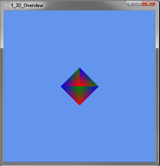
}This code is available for download in the example solution as part of the "1_3D_Overview" project.
The class starts by creating a GraphicsDeviceManager, which provides access to the video card. In Initialize, the PreferredBackBufferHeight and PreferredBackBufferWidth properties are set to the desired window height and width, respectively. The next lines describe the camera, which is covered in detail later, but for now, know that the projection is the lens of the camera and the view is the position and orientation.
In LoadContent you create a simple list of vertices with color information. A vertex is a point on a polygon, and in this case, it is a polygon of a three-dimensional diamond. It is common in 3D programming to refer to a vertex collection as a mesh. A model refers to a mesh or collection of meshes with color or texture data, and possibly animation data as well.
In the Draw method, setting the VertexDeclaration tells the GraphicsDevice what type of data is being sent. Before the data can be displayed, a BasicEffect shader is configured.
A shader is code that will run on the GPU of the graphics adapter, saving the CPU for other tasks such as physics calculations, input handling, artificial intelligence, and so on. Shaders for XNA are written in High-Level Shader Language (HLSL), which is similar to C. Shaders commonly have the extension .fx.
At a glance, shaders fall into two types — vertex shaders and pixel shaders. A vertex shader applies transformations to the vertices being rendered such as changing their position, and a pixel shader processes color information to determine the color of the pixels on screen. Shaders are covered in greater detail in the animation section; for now, just know that BasicEffect is a vertex and pixel shader included with the XNA Framework.
The location of our diamond on screen is determined by the Projection, View, and World matrices set on effect. The projection and view matrices come from our camera, and the World matrix is how the model space maps to world space. Use this matrix to adjust a mesh or model to world space, such as scaling up a model that was too small compared to the other models in the game.
All of this comes together to produce the rather boring screen shown in Figure 1.
Before I can improve upon the first example, I must cover some 3D math. Please stay with me — I promise this won't be like that college calculus class with the evil professor who lived to fail students!
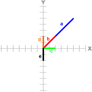
The coordinate system used in XNA 3D follows the Right-Hand Rule. This is a simple mnemonic to remember which direction is positive in 3D space. To use this mnemonic, hold your right hand so that you are looking at your palm. Make a fist and extend your thumb to the right, index finger up, and middle finger straight so that it is pointing directly at you. Your fingers are now pointing in the positive directions of each axis.
Another way to remember this (one that I prefer) is to look at the screen and raise your right hand. Your right hand is the positive direction for the X-, Y-, and Z-axes. X values increase as you move to the right, Y values increase as you move up, and Z values increase as you move toward the front of the screen.
For the positive rotation direction around an axis, picture yourself standing behind the screen. With your right hand, reach out and grab an axis. The direction your fingers wrap around the axis is the positive direction when rotating around that axis.
At the heart of 3D math is the matrix. A matrix can be thought of as a machine on a conveyer belt, processing vertices. Each matrix is programmed to perform a transformation to a vertex, and can be combined with other matrices to perform multiple transformations at once.
Strictly speaking, you are using 4×4 matrices; each matrix is a table for values with four columns and four rows. XNA provides several static methods on the Matrix structure for creating matrices, so I won't get into the details of how to perform matrix math manually. Some of the common methods used to create matrices are in the following table:
Matrix Static Method | Notes |
|---|---|
Matrix.CreateScale | Changes the scale (size) |
Matrix.CreateRotationX | Rotation around an axis |
Matrix.CreateRotationY | |
Matrix.CreateRotationZ | |
Matrix.CreateFromAxisAngle | |
Matrix.CreateFromQuaternion | |
Matrix.CreateTranslation | Translates (moves) the given amount |
Matrix.CreateLookAt | Used to create a View matrix |
Matrix.CreatePerspective | Used to create a Perspective matrix |
Matrix.CreatePerspectiveFieldOfView | |
Matrix.CreatePerspectiveOffCenter | |
Matrix.CreateOrthographic | |
Matrix.CreateOrthographicOffCenter | |
Matrix.CreateWorld | Used to create a World matrix |
In addition to these, there are methods for matrix math and specialized methods such as Matrix.CreateShadow, which will flatten your mesh to a Plane given a light direction. All of these methods (and all other similar methods in the XNA Framework) assume that (0, 0, 0) is the X, Y, Z point from which we are referencing. When I say to translate (move) to (1, 2, 4), I am really saying "from (0, 0, 0) move to (1, 2, 4)." Because of this, there is a general rule you should follow when combining matrices called ISROT (Identity, Scale, Rotate, Orbit, Translate), which is discussed later.
ISROT is a rule of thumb for combining matrices in a specific order. I is for the Identity matrix, a special matrix that does nothing. Think of it as multiplying a number by one; the result is always the number. It's not required to start with the Identity matrix in XNA, but it helps when getting started.
The next matrix in ISROT is S for the Scale matrix, which changes the size of a model or the units that you are working in. 3D models are often not in the same scale as the game, or even in the same scale with the other models.
R stands for Rotations, the next matrix to apply. Rotations are done around the point 0,0,0. A rotation can be done around the X-, Y-, or Z-axis or any arbitrary axis defined with a Quaternion, which I'll discuss later. The important part to remember is that rotations are around the object's center.
O is for Orbit, a combination step of a translation and a rotation, allowing rotations around another object. First, translate the object to the distance it should be away from the object it is orbiting. Second, rotate the object to put it in the correct place around the parent object.
Finally, with T, you move the object to its final place in the scene with Translate. This can be to a direct location, or if an Orbit was applied, move it to the location of the parent object. To make all this clear, consider an example of the Moon orbiting Earth.
First, scale the Moon to our scene dimensions. Next, rotate the Moon. (The Moon completes one rotation in the same amount of time it takes to orbit Earth, with the result being that we always see the same side of the Moon.) To move the Moon into orbit, move it the radius, or half the width, of the Earth and then complete the orbit with a rotation to align the Moon with its proper spot in its cycle. Last, move the Moon to the location of Earth in the scene. In code this might look like this:
Matrix scale       =  Matrix.CreateScale(2f);
Matrix rotate      =  Matrix.CreateRotationX(moonRotation);
Matrix orbit       =  Matrix.CreateTranslation(0f, earthRadius, 0f)
                      * Matrix.CreateRotationZ(moonOrbit);
Matrix tranlate    = Matrix.CreateTranslation(earthPosition);
To combine matrices, simply multiply them. You can store all the above operations in one matrix with the following code:
Matrix moonMatrix = Matrix.Identity * scale * rotate * orbit * tranlate;
The Vector structure in XNA is a versatile collection of numbers. From high school physics you may recall that a vector is a magnitude and a direction. Whereas 55 MPH (miles per hour) is just a speed, to make it a vector, a direction, such as north, is required. In XNA, vectors are really just a collection of numbers. The numbers may represent a true vector, a position in 3D space, or the red, green, and blue values of a font color.
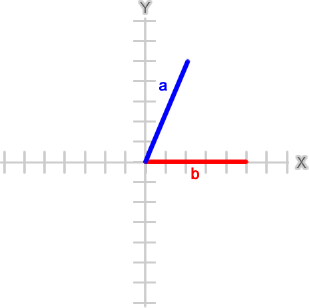
So far, I've only used a vector to represent a point in 3D space. If I wanted to use a vector's length or angle in 3D space, the vector is assumed to start at (0, 0, 0). To visualize this, consider the following vectors:
Vector3 a = new Vector3(5f, 2f, 0f);
Vector3 b = new Vector3(0f, 5f, 0f);
Drawn on a graph, these vectors would look like Figure 2 (the Z-axis is at zero for simplification):
Vector addition is performed with the + operator and is done by the Head to Tail rule. This rule means that you place the second vector's tail, or start, at the head, or end, of the first vector, as shown in Figure 3.
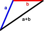
Vector addition is useful for calculating the movement of an object. For example, suppose the player fired a laser gun at an enemy robot. The starting position of the gun would be the first vector, and the distance and direction the laser should follow would be the second vector. The addition of the two vectors results in the linear trajectory of the laser.
Vector subtraction is addition of the inverse of the second vector. The inverse of a vector is a vector of equal length pointing in the opposite direction Figure 4 shows the inverse of vector b added to vector a, resulting in the subtraction of vector b from a.
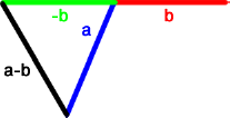
Vector subtraction is useful for calculating the distance between two objects. A common use for distance is collision detection. Imagine two balls on a pool table, approaching each other and each represented by a vector. The following code could be used to see if they have hit:
Vector3 cueBall = new Vector3(4f, 2f, 1f);
Vector3 nineBall = new Vector3(−3f, 2f, −1f);
Vector3 d = cueBall − nineBall;
if (d.Length() <= ballRadius * 2) {
    // handle ball collision
}
The Vector3.Length method is used to get the length of the distance vector, and then tested to see if that length is less than the radius of both balls. This is a very common and fast way to do collision detection known as Bounding Spheres, which is covered in the section on collision detection.
To scale a vector, use the * operator with a float value or another vector. In the previous example for addition, I would want to control the speed of the laser, so the trajectory vector should be scaled by the distance per second the laser moves. Taking time into consideration, the code for the laser's position in each frame might look like:
laserPos += laserDistPerSec * (float)gameTime.ElapsedGameTime.TotalSeconds;
Sometimes it's helpful to calculate the angle of a vector. A vector can be thought of as describing a right triangle, with the X, Y, and Z components representing potential legs and the length representing the hypotenuse. This allows you to use many concepts and functions from trigonometry. Although I won't go into depth on trig equations here, I will point out a very useful trig function you might not recall — arctangent.
Arctangent is the inverse method of tangent, which gives the ratio of the legs of a right triangle given the angle of one of the legs to the hypotenuse. Arctangent can be used to find an angle given the ratio of legs. Arctangent alone, however, is not helpful, as 2/4 and −2/−4; have the same ratio of 0.5, but the vectors (2, 4) and (−2, −4) point in opposite directions! Before you can use arctangent, you must determine if X is negative, zero, or π and handle these special cases. Thankfully, .NET provides the Math.Atan2 method, which handles the cases properly:
Math.Atan2( 2.0, 4.0)
0.46364760900080609
Math.Atan2( −2.0, −4.0)
−2.677945044588987
If you're wondering why I didn't convert the results from radians to degrees, it's because I want you to think in radians. XNA methods all expect radians, and converting adds an unnecessary step. Pi is about 3.14 and is 180 degrees (180°). The abstract class System.XNA.Framework.MathHelper provides some common radian values, shown in the following table:
MathHelper Field | Value in Radians/Degrees |
|---|---|
MathHelper.Pi | 3.14/180° |
MathHelper.PiOver2 | 1.57/90° |
MathHelper.PiOver4 | 0.79/45° |
MathHelper.TwoPi | 6.28/360° |
The last bit of information to know when working with angles is that the angle zero is the rightmost point of the circle; that is, if a circle is centered at (0, 0), then the point at which the circle intersects the positive X-axis is the zero angle.
A vector is said to be a unit vector if its length is one. These vectors are useful for finding a direction among vectors. Any vector can be normalized to a unit vector with the Normalize() instance method or by using the static version to create a new normalized version of the given vector. To show the uses of unit vectors, I'm going to define a few vectors that will be referenced in the examples:
Vector3 a = new Vector3(5f, 5f, 0f);
Vector3 b = new Vector3(2f, 2f, 0f);
Vector3 c = new Vector3(2f, 0f, 0f);
Vector3 d = new Vector3(0f, 2f, 0f);
Vector3 e = new Vector3(0f, −2f, 0f);
I've kept all the Z-axis values to zero so they are easier to visualize. On a graph, these vectors would look as shown in Figure 5.
The Vector3.Dot method calculates a vector dot product and can be used to determine the angle between two vectors. If a unit vector is used, then the dot product will be between −1.0 and 1.0 and reveals some properties of the angle.
A dot product of 1.0 means that the two vectors are parallel or point in the same direction:
Vector3.Dot(Vector3.Normalize(a), Vector3.Normalize(b))
1.0
A dot product of −1.0 means that the two vectors point in opposite directions:
Vector3.Dot(Vector3.Normalize(d), Vector3.Normalize(e))
−1.0
If the dot product is 0.0, the vectors are at a right angle:
Vector3.Dot(Vector3.Normalize(c), Vector3.Normalize(d))
0.0
The sign of the dot product can also tell us if the angle between the two vectors is acute; less than π/2 (90°) or obtuse; or greater than π/2 (90°):
Vector3.Dot(Vector3.Normalize(b), Vector3.Normalize(c))
0.707106769
Vector3.Dot(Vector3.Normalize(b), Vector3.Normalize(e))
−0.707106769
If that last answer looks funny, it's because the dot product tells us about the angle, but it is not the angle itself. To calculate the angle from a dot product, use arccosine:
Math.Acos(Vector3.Dot(Vector3.Normalize(b), Vector3.Normalize(c)))
0.78539818051171917
Math.Acos(Vector3.Dot(Vector3.Normalize(b), Vector3.Normalize(e)))
2.3561944730780739
Although the dot product can provide the angle, it does not describe the direction. Consider these two angles:
Math.Acos(Vector3.Dot(Vector3.Normalize(b), Vector3.Normalize(d)))
0.78539818051171917
Math.Acos(Vector3.Dot(Vector3.Normalize(b), Vector3.Normalize(c)))
0.78539818051171917
The angles are exactly the same, but the vectors c and d are on opposite sides of b! If b represented a turret and c was the player, a rotation using the dot product would have the turret turning away from the player. To solve this problem, you need to use a cross-product.
The cross-product calculates a direction perpendicular to a place created by two vectors, called a normal (don't confuse a normal vector with a normalized vector or unit vector). When rendering a 3D model, the graphics processor uses normal vectors to fill in only the front or outside of the model, and not waste time filling in the back or inside (this is known as backface culling or culling).
The cross-product can also be used to find the direction of a dot product. The result of a cross-product is a vector that will point in a positive or negative direction, indicating in which direction the turret should turn:
Vector3.Cross(b, d)
{X:0 Y:0 Z:4}
Vector3.Cross(b, c)
{X:0 Y:0 Z:−4}
Since you need to rotate b, the turret, around the Z-axis, you can use the sign of the cross-product with the dot product of our player c to get the final angle:
Math.Acos(Vector3.Dot(Vector3.Normalize(b), Vector3.Normalize(c)))
* Math.Sign(Vector3.Cross(b, c).Z)
−0.78539818051171917I'm almost done with the math, but there is one more concept to cover before I can move on. In the prior examples I kept the Z-axis at zero, but what about rotations along an arbitrary axis? Then you need a quaternion!
A quaternion is a rotation around a vector. You can create a quaternion explicitly with the Quaternion class or implicitly with methods like Matrix.CreateFromAxisAngle. Quaternions are sometimes represented as four-dimensional (4D) vectors that have components X, Y, Z, and W, but these values would not hold what you might expect. Consider the following two vectors:
Vector3 a = new Vector3(2f, 2f, 3f);
Vector3 b = new Vector3(2f, 2f, −3f);
I've given these vectors the same length so that it will be easy to see the quaternion in action. Using what you've learned in the section on vectors, you can calculate the cross-product and rotation angle:
Vector3.Cross(a, b)
{X:−12 Y:12 Z:0}
Math.Acos(Vector3.Dot(Vector3.Normalize(a), Vector3.Normalize(b)))
1.6296538180344839
Looking at the cross-product, it's not obvious what sign you should multiply the dot product by. Even if I figured that part out, I can't rotate this vector along the X-, Y-, or Z-axis alone — I would need to figure out a combination of all three axes. What I really want to do is rotate the vector around the cross-product, and I can do that by creating a quaternion:
Quaternion q = Quaternion.CreateFromAxisAngle(
     Vector3.Normalize(Vector3.Cross(a, b)),
     (float)Math.Acos(Vector3.Dot(Vector3.Normalize(a), Vector3.Normalize(b))));
Notice that I normalized the cross-product. Before I didn't care about the value, only the sign, but now the value will play a role in the rotation. Before I apply the rotation, take a look at the X, Y, Z, and W values of q:
q
{X:−0.5144958 Y:0.5144958 Z:0 W:0.6859943}
You might have expected W to match the value of the rotation, but it's not close. It also doesn't match the value of the dot product, which is −0.0588, and even more interesting, X, Y, and Z don't match the normalized cross-product vector, which is −0.71, 0.71, 0.0. Had I created the Quaternion with the Vector3, float constructor, these values would match up:
new Quaternion(Vector3.Normalize(Vector3.Cross(a, b)),
               Vector3.Dot(Vector3.Normalize(a), Vector3.Normalize(b)));
{X:−0.7071068 Y:0.7071068 Z:0 W:−0.05882351}
However, this would not act as expected. Quaternions are Dark Magic and are a very advanced concept that fortunately can be used by simple methods provided in the XNA Framework. To prove your quaternion q works as expected, you can use the method Vector3.Transform to apply a Matrix created from q to vector a, and it should result in being the same value as vector b:
Matrix rot = Matrix.CreateFromQuaternion(q);
Vector3.Transform(a, rot);
{X:2 Y:2 Z:−3}The 3D camera is a never-ending source of questions on the XNA Creators Club forums. I'm going to tell you the secret to the camera that will make working with it a breeze. All that math stuff covered — ISROT, vector rotation, quaternions — applies to the camera the same way it applies to any 3D object.
It's a good practice to isolate the camera logic into its own class, so I've modified the first example to use the Camera class in the following code:
public class Camera {

    public Matrix Projection;
    public Matrix View;
    public Matrix World;

    float distance;
    float rotation;
    float elevation;

    public Camera() {

        World = Matrix.Identity;
        Projection = Matrix.CreatePerspectiveFieldOfView(
            MathHelper.PiOver2, 1f, 1f, 10f);

        distance = 4f;
        rotation = 0f;
        elevation = 0f;
    }

    public void Update(GameTime gameTime) {

        KeyboardState keys = Keyboard.GetState();
        float timeScale = (float)gameTime.ElapsedGameTime.TotalSeconds;

        if (keys.IsKeyDown(Keys.Right))
rotation += MathHelper.Pi * timeScale;
else if (keys.IsKeyDown(Keys.Left))
rotation -= MathHelper.Pi * timeScale;
else if (keys.IsKeyDown(Keys.PageUp))
elevation -= MathHelper.Pi * timeScale;
else if (keys.IsKeyDown(Keys.PageDown))
elevation += MathHelper.Pi * timeScale;
else if (keys.IsKeyDown(Keys.Up))
distance -= 2f * timeScale;
else if (keys.IsKeyDown(Keys.Down))
distance += 2f * timeScale;
rotation = MathHelper.WrapAngle(rotation);
elevation = MathHelper.WrapAngle(elevation);
distance = MathHelper.Clamp(distance, 0f, 15f);
UpdateView();
}
private void UpdateView() {
Vector3 pos = new Vector3(0f, 0f, distance);
Matrix transform = Matrix.CreateRotationX(elevation)
* Matrix.CreateRotationY(rotation);
Vector3.Transform(ref pos, ref transform, out pos);
View = Matrix.CreateLookAt(pos, Vector3.Zero, Vector3.Up);
}
}The complete game code is available for download in the example solution as part of the "2_Camera" project.
The Camera class can then be used in the game with only a few changes from the previous example:
public class GameMain : Microsoft.Xna.Framework.Game {
    GraphicsDeviceManager graphics;
    VertexPositionColor[] diamond;
    Camera camera;
    Matrix shadow;
    Vector3 orbitAxis;
    float orbitDistance;
    float orbitRotation;
    float orbitSpin;
    float orbitScale;

    public GameMain() {
        graphics = new GraphicsDeviceManager(this);
    }

    protected override void Initialize() {
        graphics.PreferredBackBufferHeight = 450;
        graphics.PreferredBackBufferWidth = 450;
graphics.ApplyChanges();
camera = new Camera();
Plane floor = new Plane(Vector3.Up, 2);
Vector3 light = new Vector3(1f, 1f, 0f);
shadow = Matrix.CreateShadow(light, floor);
orbitAxis = new Vector3(1f, 0, 1f);
orbitAxis.Normalize();
orbitDistance = 2f;
orbitRotation = 0f;
orbitSpin = 0f;
orbitScale = .2f;
base.Initialize();
}
protected override void LoadContent() {
diamond = new VertexPositionColor[] {
new VertexPositionColor(new Vector3(0, 0, 1), Color.Red),
new VertexPositionColor(new Vector3(−1, 0, 0), Color.Green),
new VertexPositionColor(new Vector3(0, 1, 0), Color.Blue),
new VertexPositionColor(new Vector3(0, 0, −1), Color.Red),
new VertexPositionColor(new Vector3(0, 1, 0), Color.Green),
new VertexPositionColor(new Vector3(1, 0, 0), Color.Blue),
new VertexPositionColor(new Vector3(0, 0, 1), Color.Red),
new VertexPositionColor(new Vector3(0, −1, 0), Color.Green),
new VertexPositionColor(new Vector3(−1, 0, 0), Color.Blue),
new VertexPositionColor(new Vector3(0, −1, 0), Color.Red),
new VertexPositionColor(new Vector3(0, 0, −1), Color.Green),
new VertexPositionColor(new Vector3(1, 0, 0), Color.Blue),
};
}
protected override void Update(GameTime gameTime) {
KeyboardState keys = Keyboard.GetState();
if (keys.IsKeyDown(Keys.Escape))
this.Exit();
orbitRotation += MathHelper.PiOver2 *
(float)gameTime.ElapsedGameTime.TotalSeconds;
orbitRotation = MathHelper.WrapAngle(orbitRotation);
orbitSpin += MathHelper.TwoPi *
(float)gameTime.ElapsedGameTime.TotalSeconds;
orbitSpin = MathHelper.WrapAngle(orbitSpin);
camera.Update(gameTime);
base.Update(gameTime);
}
protected override void Draw(GameTime gameTime) {graphics.GraphicsDevice.Clear(Color.CornflowerBlue);
graphics.GraphicsDevice.VertexDeclaration = new VertexDeclaration(
graphics.GraphicsDevice, VertexPositionColor.VertexElements);
BasicEffect effect = new BasicEffect(graphics.GraphicsDevice, null);
effect.VertexColorEnabled = true;
effect.Projection = camera.Projection;
effect.View = camera.View;
effect.World = camera.World;
effect.Begin();
foreach (EffectPass pass in effect.CurrentTechnique.Passes) {
pass.Begin();
effect.GraphicsDevice.DrawUserPrimitives<VertexPositionColor>(
PrimitiveType.TriangleStrip, diamond, 0, diamond.Length − 2);
pass.End();
}
effect.End();
Matrix satellite = Matrix.Identity
* Matrix.CreateScale(orbitScale)
* Matrix.CreateRotationY(orbitSpin)
* Matrix.CreateTranslation(0f, orbitDistance, 0f)
* Matrix.CreateFromAxisAngle(orbitAxis, orbitRotation);
effect.View = satellite * camera.View;
effect.Begin();
foreach (EffectPass pass in effect.CurrentTechnique.Passes) {
pass.Begin();
effect.GraphicsDevice.DrawUserPrimitives<VertexPositionColor>(
PrimitiveType.TriangleStrip, diamond, 0, diamond.Length − 2);
pass.End();
}
effect.End();
// Render Shadow Effects
effect.EnableDefaultLighting();
effect.VertexColorEnabled = false;
effect.EmissiveColor = Color.Black.ToVector3();
effect.View = shadow * camera.View;
effect.Begin();
foreach (EffectPass pass in effect.CurrentTechnique.Passes) {
pass.Begin();
effect.GraphicsDevice.DrawUserPrimitives<VertexPositionColor>(
PrimitiveType.TriangleStrip, diamond, 0, diamond.Length − 2);
pass.End();
}
effect.End();
effect.View = satellite * shadow * camera.View;
effect.Begin();
foreach (EffectPass pass in effect.CurrentTechnique.Passes) {
pass.Begin();effect.GraphicsDevice.DrawUserPrimitives<VertexPositionColor>(
PrimitiveType.TriangleStrip, diamond, 0, diamond.Length − 2);
pass.End();
}
effect.End();
base.Draw(gameTime);
}
}The output of the game is shown in Figure 6:
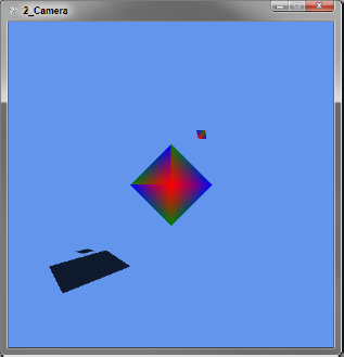
The class has three public fields — Projection, View, and World — that are used in the game's Draw method. The game is also required to call the camera's Update method during its own Update. Often the camera Update call is last, after all other game logic, so that the camera can be updated to the current state of the game.
The World matrix is set to Matrix.Identity. The Projection matrix is set with Matrix.CreatePerspectiveFieldOfView and defines the "lens" of the camera. The first parameter establishes the field of view, which is an angle describing how wide or narrow the camera lens is. Increasing this value will show more of the world, and objects will appear smaller at the same distance than a larger value. The field of view must be between zero and π and cannot be exactly zero or π.
The second parameter is the aspect ratio of the field of view, defined as width divided by height. If this is set to the same dimensions as the game window (or current ViewPort), the objects appear without distortion. If the aspect ratio is set to a value other than the actual ratio of the height and width, the objects will appear stretched or squished in width or height.
The last two parameters establish the near view plane, and far view plane. Objects that are between these two planes will be rendered; objects that are not will be ignored. If an object is on a boundary, only the portion between the view planes will be rendered. The values describe how far in front of the camera each plane is and must be positive with the far plane greater than the near plane.
Instead of creating a View matrix that is altered in each Update, I have chosen to track some variables of the camera — distance, rotation, and elevation. Keeping these "ingredients" apart makes it easier to change and "bake" the View matrix at the end. The rotation of the camera is controlled with the left/right arrow keys, and the up/down arrow keys control the distance or zoom of the camera. The [Page Up]/[Page Down] keys control the elevation, or a rotation around the X-axis.
The UpdateView method creates the final View matrix, using the Matrix.CreateLookAt method, which requires three vectors to describe the camera's orientation. The first Vector is the position of the camera, and the second Vector is the target. Together they establish the direction the camera is facing. The third Vector describes the up direction for the camera; changing this value would have the effect of rolling the camera over or holding it upside down.
In this example, the camera is looking at the center with a constant up direction, and only the position is changing. The order in which you bake the position is important. If you did the rotation before the elevation, you would need to calculate a new normal to rotate the elevation around since you would no longer be perpendicular to the X-axis. It can be done, but keeping the ingredients separate keeps the math simple and allows you to follow the ISROT rule.
If you play with the camera and rotate the elevation past π/2 (the "top" point), it will flip the scene. What's actually happening is the pos.Z value is negative when the elevation is greater than π/2, and this changes the up direction of the camera. However, you do not want to change the up Vector when the camera is at a negative pos.Z value, since that is possible through the rotation value as well.
I had this exact problem when working on IncaBlocks. I don't know if my fix counts as a solution — I limited the elevation to less than π/2. This allowed the pos.Z value to be negative only through changes in rotation. Sometimes it's worth asking if the player really needs to be able to move the camera in odd ways!
Although a follow camera is really just a variation on a normal camera, it is so common in 3D games that it's worth mentioning here. A follow camera is a camera that follows another object in the game and typically does not handle input directly from the player. An example is a third-person shooter, where the camera is positioned behind the player and faces in the direction the player is looking.
Here is a follow camera that follows the orbiting diamond from the previous example:
public class Camera {

    public Matrix Projection;
    public Matrix View;
    public Matrix World;

    Vector3 startPos;
    Vector3 startTarget;
    Vector3 startUp;

    public Camera() {

        World = Matrix.Identity;
        Projection = Matrix.CreatePerspectiveFieldOfView(
            MathHelper.PiOver2, 1f, .1f, 10f);

        startPos = new Vector3(1.5f, 1.5f, 1f);
        startTarget = new Vector3(−1f, −1f, −1f);
        startUp = Vector3.Up;
    }

    public void Update(float scale, float distance, float rotation,
                       Vector3 axis) {

        Matrix transform = Matrix.Identity
                         * Matrix.CreateScale(scale)
                         * Matrix.CreateTranslation(0f, distance, 0f)
                         * Matrix.CreateFromAxisAngle(axis, rotation);

        Vector3 pos = Vector3.Transform(startPos, transform);
        Vector3 tar = Vector3.Transform(startTarget, transform);
        Vector3 up = Vector3.Transform(startUp, transform);

        View = Matrix.CreateLookAt(pos, tar, up);
    }
}
The complete game code is available for download in the example solution as part of the "3_Follow_Camera" project.
The game produces the screen shown in Figure 7:
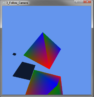
This camera keeps three private fields as "ingredients" that describe where the camera should be positioned and facing relative to the object that it is following. If using a 3D model from a 3D design program, it's common that these vectors are set in the model data as a special object. The View matrix is created by applying the same matrix transform to the position, target, and up Vectors as the target object. Indeed, the Transform matrix for the orbiting diamond is nearly identical to the camera transform:
Matrix satellite = Matrix.Identity
                 * Matrix.CreateScale(orbitScale)
                 * Matrix.CreateRotationY(orbitSpin)
                 * Matrix.CreateTranslation(0f, orbitDistance, 0f)
* Matrix.CreateFromAxisAngle(orbitAxis, orbitRotation);Many games need more than one camera. Multiplayer games often include a split-screen option to support two or more players on the same screen. Inca Blocks requires four cameras during the game play to show the board, current piece, available pieces, and the player's Xbox Live Avatar. The ViewPort structure is designed to make this task a breeze.
In simple terms, a ViewPort is a window inside the game's main window. In full terms, it is the dimensions of a render-target surface onto which 3D volume projects. A ViewPort is defined by Height, Width, X, and Y values in 2D screen space. When the GraphicsDevice is set to the ViewPort, all 3D rendering takes place within the bounds of the ViewPort, and any objects outside the ViewPort are not rendered.
To demonstrate ViewPorts in action, I've modified the prior scene to use both the normal camera and the follow camera. In the game's Initialize method, I've added the following lines to set up the viewports added to the GameMain class:
graphics.PreferredBackBufferHeight = 450;
graphics.PreferredBackBufferWidth = 900;
graphics.ApplyChanges();

followCamera = new FollowCamera();
camera = new Camera();

viewLeft = new Viewport() {
    Height = 450,
    Width = 450,
    X = 0,
    Y = 0
};

viewRight = new Viewport() {
    Height = 450,
    Width = 450,
    X = 450,
    Y = 0
};

viewFull = graphics.GraphicsDevice.Viewport;
The first change is doubling the screen width to fit the two ViewPorts on screen. Then I set up both cameras and ViewPorts for the left and right sides of the screen. Finally, I save the current ViewPort, which is the full screen, so that it can be referenced as well when clearing the screen between frames.
The Draw method now uses these cameras and ViewPorts:
protected override void Draw(GameTime gameTime) {
    graphics.GraphicsDevice.Viewport = viewFull;
    graphics.GraphicsDevice.Clear(Color.CornflowerBlue);
    graphics.GraphicsDevice.VertexDeclaration = new VertexDeclaration(
        graphics.GraphicsDevice, VertexPositionColor.VertexElements);

    graphics.GraphicsDevice.Viewport = viewLeft;
    DrawScene(camera);

    graphics.GraphicsDevice.Viewport = viewRight;
    DrawScene(followCamera);

    base.Draw(gameTime);
}
The complete game code is available for download in the example solution as part of the "4_ViewPort."
Figure 8 shows the viewports in action:
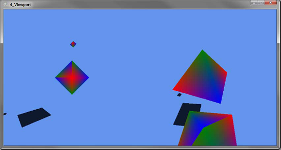
First, the viewFull ViewPort is set, so that the Clear() call clears the entire screen. Then the GraphicsDevice.ViewPort is set to the viewLeft ViewPort, and the scene is drawn with the basic camera. The process is repeated with the viewRight ViewPort and followCamera.
Before moving on from discussing the camera, I want to mention the BoundingFrustum class. A frustum is a 3D pyramid shape, with the top flat instead of coming to a point, and both the top and bottom planes of the pyramid are rectangles. A frustum can describe the area the camera sees, and you can create a BoundingFrustum from a View and Projection matrix:
BoundingFrustum b = new BoundingFrustum(cameraView * cameraProjection);
To see if a 3D object is inside of or intersects the frustum, use the BoundingFrustum Contains() and Intersects() methods. I discuss these methods more in the collision detection section, but I want to mention them here because these methods can be used if you need to know if the player can see an object.
In all the examples so far, I've been creating 3D objects in code using VertexPositionColor and rendering as a PrimitiveType.TriangleStrip. This is useful for getting something up fast, but has limitations. Consider the code to define the diamond shape:
diamond = new VertexPositionColor[] {
    new VertexPositionColor(new Vector3(0, 0, 1), Color.Red),
    new VertexPositionColor(new Vector3(−1, 0, 0), Color.Green),
    new VertexPositionColor(new Vector3(0, 1, 0), Color.Blue),
    new VertexPositionColor(new Vector3(0, 0, −1), Color.Red),
    new VertexPositionColor(new Vector3(0, 1, 0), Color.Green),
    new VertexPositionColor(new Vector3(1, 0, 0), Color.Blue),
    new VertexPositionColor(new Vector3(0, 0, 1), Color.Red),
    new VertexPositionColor(new Vector3(0, −1, 0), Color.Green),
    new VertexPositionColor(new Vector3(−1, 0, 0), Color.Blue),
    new VertexPositionColor(new Vector3(0, −1, 0), Color.Red),
    new VertexPositionColor(new Vector3(0, 0, −1), Color.Green),
    new VertexPositionColor(new Vector3(1, 0, 0), Color.Blue),
};
When the call to GraphicsDevice.DrawUserPrimitives is made with the PrimitiveType.TriangleStrip, the array is read as a sequence of overlapping triangles. Elements 0, 1, and 2 form the first triangle; elements 1, 2, and 3 form the second; 2, 3, and 4 form the third; and so on. An alternative, but more verbose, form would be to define a PrimitiveType.TriangleList, in which elements 0, 1, and 2 are the first triangle; 3, 4, and 5 are the second; 6, 7, and 8 are the third; and so on. This form would also require more memory, and more time processing transforms.
Although there is good support for defining objects in code, this will become cumbersome quickly. Just creating the diamond for this example, I needed scratch paper! Imagine the code to define a soldier, his gear, and his rifle, and then add to this the code to map a texture to the model. A better solution is to model the object in a 3D modeling program, then load that model in XNA.
There are many 3D modeling programs that range from free, such as Blender, to expensive, such as 3D Studio Max and Maya, which can run several thousand dollars per license. If you join the XNA Creators Club (an annual fee of $99 USD at time of writing), you have access to Autodesk's Softimage Mod Tool Pro. All these tools share one thing in common — they have steep learning curves. If you want to create 3D models, plan on spending a few weeks just learning how the program works.
There are just as many, if not more, file formats as modeling tools. XNA has built-in support for DirectX (.x) and Autodesk FBX (.fbx) formats. There are examples for other formats, and it's possible to write a file importer, but when starting out, it's easiest to make sure that your modeling program supports at least one of these formats.
Let's take a look at loading a 3D model in XNA:
public class GameMain : Microsoft.Xna.Framework.Game {
    GraphicsDeviceManager graphics;
    Camera camera;
    Model robot;

    public GameMain() {
        graphics = new GraphicsDeviceManager(this);
    }

    protected override void Initialize() {
        graphics.PreferredBackBufferHeight = 450;
        graphics.PreferredBackBufferWidth = 450;
        graphics.ApplyChanges();

        camera = new Camera();
        Content.RootDirectory = "Content";

        base.Initialize();
    }

    protected override void LoadContent() {
        robot = Content.Load<Model>("Robot");
    }

    protected override void Update(GameTime gameTime) {
        KeyboardState keys = Keyboard.GetState();

        if (keys.IsKeyDown(Keys.Escape))
            this.Exit();

        camera.Update(gameTime);
        base.Update(gameTime);
    }

    protected override void Draw(GameTime gameTime) {
        graphics.GraphicsDevice.Clear(Color.CornflowerBlue);
        graphics.GraphicsDevice.VertexDeclaration = new VertexDeclaration(
            graphics.GraphicsDevice, VertexPositionColor.VertexElements);

        foreach (BasicEffect effect in robot.Meshes["Robot"].Effects) {
            effect.EnableDefaultLighting();
            effect.EmissiveColor = Color.White.ToVector3();
            effect.View = camera.View;
            effect.Projection = camera.Projection;
            effect.World = robot.Bones["Robot"].Transform * camera.World;
        }
robot.Meshes["Robot"].Draw();
base.Draw(gameTime);
}
}The complete game code is available for download in the example solution as part of the "5_LoadModel" project.
Figure 9 shows the robot model loaded in XNA:
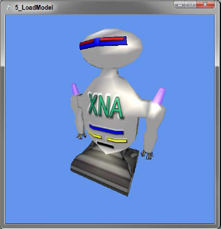
The first new item here is setting the Content.RootDirectory property. This tells XNA where the model data is stored on disk. This folder is loaded as a Content project in the XNA Game project, which compiles model, texture, and music data into a usable format by XNA at run time. The Microsoft.Xna.Framework.Game class that my game derives from provides a ContentManager instance through the Content property.
When you create a new XNA project, a Content project is automatically created and set in a subfolder named Content. More Content projects can be added as needed, and multiple ContentManager instances can be created at run time. Indeed, this will be required on larger games as content loaded from a ContentManager stays in memory until ContentManager.Unload () is called. The XNA Framework will unload any content loaded by the Game.Content instance; any additional ContentManager instances should be unloaded explicitly by overriding the Game.UnloadContent() method.
In LoadContent, the call Content.Load<Model>("Robot") loads the model into memory. The Model class in XNA wraps the steps to draw the model on the screen in the Model.Draw() method, but the BasicEffect shader should be configured before calling this method.
A Model can hold multiple 3D objects, which are stored in the Meshes property. The name for the mesh is set in the 3D modeling tool. Meshes also hold a collection named Bones, which contains not only data for animations, but also transform information for mapping the 3D modeling tool's World matrix to the XNA World matrix. This transform is stored in a Bone named the same as the Mesh, and can also be accessed using the Mesh.ParentBone property.
Bones may also be used to store special information about the model as well. In the example model, I included two special bones called CameraPosition and CameraTarget that contain the information needed to build a follow camera behind the robot. The following code shows using these bones to construct a view matrix:
view = Matrix.CreateLookAt(
    Vector3.Transform(Vector3.Zero, robot.Bones["CameraPosition"].Transform),
    Vector3.Transform(Vector3.Zero, robot.Bones["CameraTarget"].Transform),
    robot.Bones["CameraPosition"].Transform.Up
);
The complete game code is available for download in the example solution as part of the "6_Model_Camera" project.
Figure 10 shows the over-the−shoulder follow camera defined in the model data:
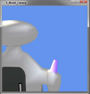
Since the robot isn't moving, I can hard-code the start position as (0, 0, 0). In a game where the robot would be moving, Vector3.Zero would replace its current position.
Collision detection is the process of determining if two objects intersect. In two dimensions, this involves checking to see if one sprite shares the same pixels as another; in three dimensions, however, things are a bit more complex.
The easiest and most common method for 3D collision detection is done using spheres. Each 3D object is assigned a sphere that wraps the object. Collisions are tested for by calculating the distance between two spheres, and a collision is true if this distance is less than the sum of the radius of both spheres.
To represent a sphere, only two pieces of information are needed — a point for the location and a measure of the radius. XNA provides a BoundingSphere structure that has a Vector3 for the position and a float for the radius. BoundingSphere provides two methods to aid in collision detection — BoundingSphere.Intersects, which tests just for intersection; and BoundingSphere.Contains, which will return an enumeration if the second object intersects the sphere, is contained by the sphere, or is disjointed (having no overlap between the two objects).
In the following code, I take the diamond VertexPositionColor Array from previous examples and create a BoundingSphere for collision detection:
diamondSphere = BoundingSphere.CreateFromPoints(
    from v in diamond select v.Position);
diamondSphere.Center = diamondPosition;
diamondSphere.Radius *= diamondScale;
The complete game code is available for download in the example solution as part of the "7_Collision_Detection" project.
Since I know the diamond has a radius of 1, I could have created the BoundingSphere with new BoundingSphere(diamondPosition, diamondScale); however, this method has the advantage of not needing to know anything about the points that make up the diamond object.
Getting a BoundingSphere for a Model Mesh is even easier since one is created and stored in Mesh.BoundingSphere. Before using this BoundingSphere, however, any transforms applied to the Mesh must be applied to the BoundingSphere.
This example shows collision detection between the robot Model from the previous section, and our diamond BoundingSphere:
Vector3 newPosition = robotPosition;

if (keys.IsKeyDown(Keys.Up))
    newPosition += Vector3.Transform(new Vector3(0, 0, 4 * eTime),
                        Matrix.CreateRotationY(robotRotation));
else if (keys.IsKeyDown(Keys.Down))
    newPosition += Vector3.Transform(new Vector3(0, 0, −4 * eTime),
                        Matrix.CreateRotationY(robotRotation));

Matrix newTransform = Matrix.CreateRotationY(robotRotation)
                    * Matrix.CreateTranslation(newPosition);

BoundingSphere robotSphere = robot.Meshes["Robot"].BoundingSphere;
robotSphere.Center = Vector3.Transform(robotSphere.Center, newTransform);

if (!robotSphere.Intersects(diamondSphere))
    robotPosition = newPosition;

robotTransform = Matrix.CreateRotationY(robotRotation)
               * Matrix.CreateTranslation(robotPosition);
The complete game code is available for download in the example solution as part of the "7_Collision_Detection" project.
First, a new position is used so if a collision is detected, the robot's movement can be canceled. The transform to the movement is applied because the robot may be facing any direction, so the "forward" direction needs to be adjusted. Once the new position is calculated, the robot's BoundingSphere is moved to that position, and the test for collision is performed.
Spheres do have a key limitation in that they only represent an approximation of the mesh's space, and not the actual space the mesh occupies. If one object was a laser fired at the robot, the player may not be OK with this approximation.
When a single sphere isn't enough, a popular method is to have spheres added to the model that are not rendered, but used for collision detection. The robot, for example, could have a sphere around the body, one for the upper arm, another for the lower arm, and another for the head and hand. If the outer sphere detected a collision, each inner sphere could be tested for a higher resolution of detection.
XNA also provides a BoundingBox, a BoundingFrustum, and overloads for testing collisions across all combinations of spheres, boxes, and frustums. If a sphere is a bad fit for the mesh, one of these other shapes can be used. Using spheres, however, is the fastest method.
In the previous examples, I've used what is known as Rigid Body Animation. In Rigid Body Animation, the entire object is animated. If I wanted to animate just the arms, I would need to have the arms as a separate mesh that contained information needed to translate them into the proper location. Within a full game, there might be hundreds of meshes at any one time, and this would be hard to keep track of. Furthermore, if I wanted to deform a mesh, to make Santa's belly shake, for example, I would need to understand the makeup of the vertices inside the mesh. Skeletal animations can solve this problem.
As the name implies, skeletal animations modify a skeleton that is attached to a mesh. Skeletons are composed of bones, and each vertex contains a weight value that determines how much of the vertex's position is determined by the location of each bone. The XNA Model class doesn't support skeletal animations, but the XNA Framework provides everything needed to add this support and use skeletal animations in a game.
Before skeletal data can be used in a model, the data needs to be extracted from the file and into a custom object. A brief overview of the process: First, extract the skeletal data and then replace the default BasicEffect shader, which doesn't support skeletal animations, with a custom shader. This is done with a Content Pipeline Processor project, and a Content Library project is created that defines the data structure for the skeletal animation. The Library project is shared by both the Game project and the Processor project. The Processor project is referenced from the Game's Content project. Enough theory — put this into practice!
The first step is creating a content processor to extract the skeleton and add the custom shader. Content processors are invoked at build time by Visual Studio when compiling game content and do not take part during game run time. XNA provides a template for processor projects in the "Add New Project" dialog, under Visual C#/XNA Game Studio 3.1/Content Pipeline Extension Library. I've created an example processor for the robot model:
[ContentProcessor(DisplayName = "AnimatedModel − XNA 3D Primer")]
public class AnimatedModelProcessor : ModelProcessor {

    public override ModelContent Process(NodeContent input,
                                         ContentProcessorContext context) {
        BoneContent skel = MeshHelper.FindSkeleton(input);
        IList<BoneContent> bones = MeshHelper.FlattenSkeleton(skel);

        MeshAnimationInfo ani = new MeshAnimationInfo();
        foreach (BoneContent bone in bones) {
            ani.BoneNames.Add(bone.Name, bones.IndexOf(bone));
            ani.BoneParent.Add(bones.IndexOf(bone.Parent as BoneContent));
            ani.BoneTransforms.Add(bone.Transform);
            ani.InverseBoneTransforms.Add(
                Matrix.Invert(bone.AbsoluteTransform));
        }

        ModelContent model = base.Process(input, context);
        model.Tag = ani;

        return model;
    }

    protected override MaterialContent ConvertMaterial(MaterialContent material,
                                              ContentProcessorContext context) {
        String effectFile = Path.GetFullPath("Animation.fx");
        EffectMaterialContent effectMaterial = new EffectMaterialContent();
        effectMaterial.Effect =
            new ExternalReference<EffectContent>(effectFile);

        foreach (var texture in material.Textures)
            effectMaterial.Textures.Add(texture.Key, texture.Value);

        return base.ConvertMaterial(effectMaterial, context);
    }
}
The complete game code is available for download in the example solution as part of the"XNA_3D_Primer_Pipeline.Processors" project.
The ContentProcessor Attribute identifies this class as a content processor. Since I only want to extend the default model processing, this class inherits XNA's ModelProcessor class. The ModelProcessor class is the class that handled our robot model in the previous sections.
MeshHelper.FindSkeleton finds the root bone of the skeleton attached to the mesh being processed. A list of all bones, including the root bone, is loaded with MeshHelper.FlattenSkeleton. Once all bones are found, data about the bones and skeleton are copied into the custom class MeshAnimationInfo, defined in the Content Library project XNA_3D_Primer_Pipeline.Content project.
Each bone has four pieces of information needed. The first is simply a name to index mapping. In the robot model, the bones are given names like Head, RightShoulder, and RightArm to make it easy to find and manipulate the desired bone. Next, a list to map each bone to its parent is made. If a transform is applied to a bone, such as moving the RightShoulder, the same transform will need to be applied to the children, in this case, the RightArm. Although the bones are logically connected, XNA does not enforce any rules on how bones interact with each other; that is the job of the developer.
The last two items saved are transforms. The first is the bone transform, which tells you how the bone moved from the center to its proper location. Knowing the center of the bone is important for applying transforms. Look at your own arm bone and imagine if it rotated from the wrist instead of the elbow. This would be very convenient if you sought a job in a carnival, but it would be a problem in all other situations! The other transform is the inverse of the bone's AbsoluteTransform. The AbsoluteTransform includes the bone's transform from center, plus any parent bone transforms. By applying the inverse of this transform to the bone, we can "back out" any transformations and make it easy to add custom transformations. If custom transforms were applied without this step, it would break the ISROT rule, and things would not end up where expected.
The skeletal data is stored in the Model.Tag property, which is of type object and is intended to hold custom data. The XNA Framework doesn't do anything with this property, except store and load it with the model.
The second method in AnimatedModelProcessor, ConvertMaterial, replaces the BasicEffect default shader with a custom shader named Animation.fx. There isn't anything exciting happening here, except a loop that copies over the texture data to the new effect.
Here is an example of setting the [W] and [S] keys to move the robot's arm using the skeletal data loaded from the content processor:
protected override void LoadContent() {
    robot = Content.Load<Model>("Robot");
    robotAni = robot.Tag as MeshAnimationInfo;
    robotTransforms = new Matrix[robotAni.BoneTransforms.Count];
}

protected override void Update(GameTime gameTime) {
    KeyboardState keys = Keyboard.GetState();

    float eTime = (float)gameTime.ElapsedGameTime.TotalSeconds;

    if (keys.IsKeyDown(Keys.Escape))
        this.Exit();
    else if (keys.IsKeyDown(Keys.S))
        armAngle += 1f * eTime;
    else if (keys.IsKeyDown(Keys.W))
armAngle −= 1f * eTime;
armAngle = MathHelper.Clamp(armAngle, −1 * MathHelper.PiOver2, 0f);
robotAni.BoneTransforms.CopyTo(robotTransforms);
robotTransforms[robotAni.BoneNames["RightArm"]] =
Matrix.CreateRotationY(armAngle)
* robotTransforms[robotAni.BoneNames["RightArm"]];
robotTransforms[robotAni.BoneNames["LeftArm"]] =
Matrix.CreateRotationY(armAngle)
* robotTransforms[robotAni.BoneNames["LeftArm"]];
robotTransforms[robotAni.BoneNames["LeftShoulder"]] =
Matrix.CreateRotationY(armAngle) *
robotTransforms[robotAni.BoneNames["LeftShoulder"]];
for (int i = 1; i < robotTransforms.Length; i++)
robotTransforms[i] = robotTransforms[i]
* robotTransforms[robotAni.BoneParent[i]];
for (int i = 0; i < robotTransforms.Length; i++)
robotTransforms[i] = robotAni.InverseBoneTransforms[i]
* robotTransforms[i];
camera.Update(gameTime);
base.Update(gameTime);
}
protected override void Draw(GameTime gameTime) {
graphics.GraphicsDevice.Clear(Color.CornflowerBlue);
graphics.GraphicsDevice.VertexDeclaration = new VertexDeclaration(
graphics.GraphicsDevice, VertexPositionColor.VertexElements);
foreach (Effect effect in robot.Meshes["Robot"].Effects) {
effect.Parameters["Bones"].SetValue(robotTransforms);
effect.Parameters["View"].SetValue(camera.View);
effect.Parameters["Projection"].SetValue(camera.Projection);
effect.Parameters["World"].SetValue(robot.Bones["Robot"].Transform
* camera.World);
}
robot.Meshes["Robot"].Draw();
base.Draw(gameTime);
}The complete game code is available for download in the example solution as part of the"8_Animation" project.
Figure 11 shows the animated robot model, though I recommend running the example code to see the animation in action:
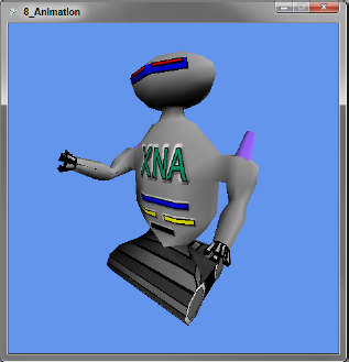
In LoadContent the custom MeshAnimationInfo class is pulled out and the Matrix array robotTransforms to hold the bone manipulation transforms is initialized. It is important to note that the bones in the skeleton are not all of the bones in the Model.Bones array and have a different index from the copy there. The bones in the skeleton are the bones that affect the robot mesh and have indexes that match the vertex bone weight data used by the shader.
The bone manipulation logic is in the Update method, after the input handling code. The first step is to initialize the robotTransforms array with the default bone transforms using the BoneTransforms.CopyTo() method. Then custom transforms are created by first applying the custom transform, and then the bone's transform (order is key here). Next, all the bone transforms are combined with their parent transforms. (Notice that the loop starts from one — the first bone is the root and has no parent.) Last, we need to make sure that our transforms are applied at the correct center points by using the list of inverse absolute transforms (again, order is key). Think of the last step as moving the bone back to the center, then to our new position.
In the Draw method, the final list of robotTransforms is passed to the custom shader through the Bones parameter. Since BasicEffect is no longer in use, setting the World, View, and Projection must be done with SetValue calls on the Parameters collection. This method also works with BasicEffect, and the properties are provided as convenience only.
The shader contains the code that will adjust each vertex given the list of transforms and the bone weight data for each vertex. The code for the Animation.fx shader is written in High Level Shader Language (HLSL) and is a C#-like language for creating custom shaders easily. Covering HLSL in full is beyond the scope of this Wrox Blox, but I will walk through the points needed for skeletal animation:
float4x4 World;
float4x4 View;
float4x4 Projection;
texture Texture;

// Shader spec 2.0 allows for a max of 59 bones
#define MaxBones 59
float4x4 Bones[MaxBones];

sampler TexSampler = sampler_state
{
    Texture = (Texture);
};

float3 LightDirection1 = normalize(float3(1, 1, 2));
float3 LightDirection2 = normalize(float3(1, 1, −2));
float3 LightColor = float3(1, 1, 1);

struct VertexShaderInput
{
    float4 Position : POSITION0;
    float3 Normal : NORMAL0;
    float2 TextureCoord : TEXCOORD0;
    float4 BoneIndex : BLENDINDICES0;
    float4 BoneWeight : BLENDWEIGHT0;
};

struct VertexShaderOutput
{
    float4 Position : POSITION0;
    float2 TextureCoord : TEXCOORD0;
    float3 Light1 : COLOR0;
    float3 Light2 : COLOR1;
};


VertexShaderOutput VertexShaderFunction(VertexShaderInput input)
{
    VertexShaderOutput output;
    output.TextureCoord = input.TextureCoord;

    float4x4 boneTransform = 0;
    boneTransform += Bones[input.BoneIndex.x] * input.BoneWeight.x;
    boneTransform += Bones[input.BoneIndex.y] * input.BoneWeight.y;
    boneTransform += Bones[input.BoneIndex.z] * input.BoneWeight.z;
    boneTransform += Bones[input.BoneIndex.w] * input.BoneWeight.w;

    float4 bonePosition = mul(input.Position, boneTransform);
    float4 worldPosition = mul(bonePosition, World);
    float4 viewPosition = mul(worldPosition, View);
    output.Position = mul(viewPosition, Projection);

    float3 normal = normalize(mul(input.Normal, boneTransform));
    output.Light1 = max(dot(normal, LightDirection1), 0) * LightColor;
    output.Light2 = max(dot(normal, LightDirection2), 0) * LightColor;

    return output;
}
float4 PixelShaderFunction(VertexShaderOutput input) : COLOR0
{
float4 color = tex2D(TexSampler, input.TextureCoord);
color.rgb *= (input.Light1 + input.Light2);
return color;
}
technique Technique1
{
pass Pass1
{
VertexShader = compile vs_2_0 VertexShaderFunction();
PixelShader = compile ps_2_0 PixelShaderFunction();
}
}Many things in HLSL happen automatically when conventions are followed. The first example of this is at the top of the file: The variables World, View, Projection, Bones, and Texture become parameters because they are defined globally. LightDirection1, LightDirection2, and LightColor are also parameters and have default values assigned to them.
Two structures define what data is passed to the vertex shader and pixel shader — VertexShaderInput and VertexShaderOutput. These structures can be named anything, and the fields in the structure are also able to be named anything. The part after the colons, however, is controlled by the HLSL specification (in this case, 2.0, which is the highest version supported by Xbox 360). The names after the colon map vertex data to the structures used as input and output data in the shaders.
The first shader is the vertex shader and will be called for every vertex in the Mesh. The vertex shader's main job is to determine the final position of the vertex. Since nothing done in the vertex shader will alter the texture coordinates, these are simply copied over as is. Then a matrix is created (a matrix is really a set of 16 numbers in 4 rows and 4 columns and can be represented as a float4×4 in HLSL). This matrix is created by multiplying the X, Y, Z, and W components by their weight values, which range from zero to one.
In this shader, I am only checking the first bone controlling the vertex, but it is possible that one vertex is controlled by two or more bones. Consider the skin at your elbow; the position is determined by your upper arm bone (humerus) and both forearm bones (radius and ulna). To handle multiple bones in a shader, add a BLENDINDICESX and a BLENDWEIGHTX for each additional bone (replace X with the index of the bone), and then create a combined transform.
The next lines multiply (using the HLSL mul function) the matrices into a final transformed position. The secret's out: The World, View, and Projection matrices are just abstractions for convenience — at the shader level, they are combined into one matrix.
The last task is to alter the normal vector (recall that the normal vector is the vector perpendicular to the surface of the vertex's plane) and then use the transformed normal in calculating how the lights affect the output color. The intensity of the light is determined by the dot product of the light direction to the normal. If the light is parallel to the normal, this value would be one, and the light would be at full strength; if the light is perpendicular, it would have no effect (the dot product would be zero); and if the light is "under" the normal plane, the max HLSL function would set the negative dot product result to zero, and the light would have no effect.
The pixel shader picks up where the vertex shader left off, and is called for every pixel going to the screen. The texture data is read with the tex2D HLSL method using the TexSampler set at the top of the file and in the texture coordinates. Texture coordinates are a pair of numbers between zero and one with each vertex referred to commonly as U and V. U and V map to the X and Y coordinates of a 2D image file and specify how the texture "wraps" the 3D model. The only change made in the pixel shader to the color of the texture pixel is applying the light color.
The last section of the shader defines the names of the shader functions and which version of HLSL these functions support. A shader can have multiple passes, so the results of one pass can be chained to the next pass. A shader may also have multiple techniques, which makes it simple to group passes and call them from the XNA/C# side.
I know the last section may have left you dizzy, but if you have worked through it a few times you are only a tweak away from using animation timelines created in the 3D modeling tool in a game! It's a lot of information to process, so don't feel bad if it takes a few readings to "click" — it took me a month to get to that point and was my motivation to write this Wrox Blox.
Timeline animations are a set of key frames and bone transforms. At each key frame, a list of indexed transforms describes the skeleton bone transforms for that frame. These transforms are applied exactly the same as the transforms applied in the previous example. The first tweak to the last example is getting the list of key frames from the model data. The following code added to the Content Pipeline Processor extracts the key frames and adds them to MeshAnimationInfo:
foreach (var timeline in skel.Animations) {
    foreach (var bone in timeline.Value.Channels) {
        Int32 boneIdx = ani.BoneNames[bone.Key];
        foreach (var frame in bone.Value) {
            if (!ani.Timelines.ContainsKey(timeline.Key))
                ani.Timelines[timeline.Key] = new List<AnimationFrame>();
            if (ani.Timelines[timeline.Key].Count − 1
                < bone.Value.IndexOf(frame))
                ani.Timelines[timeline.Key].Add(
                    new AnimationFrame() { Time = frame.Time });
            ani.Timelines[timeline.Key][bone.Value.IndexOf(frame)].
                BoneTransforms[boneIdx] = frame.Transform;
        }
    }
}
To work through this example, it helps to first know how animation data is stored. In the model data is a list of timelines in the skeleton's Animation property. A timeline has a list of Channels that are the bones affected in the animation. Each bone holds the list of frames the bone is involved in.
I find this hierarchy confusing and error-prone, so I copy the data to a new hierarchy of timelines, frames, and bone transforms. I also find it easier to use an integer index of the frame number than the frame's Time property, which is a TimeSpan. With a frame number, I can jump to a specific frame, but using a TimeSpan for an index, I would need to loop over each key, see if the key was greater than the value I am searching for, and if so, use the prior key as the index value.
Frame number indexing also solved a few format problems I ran into with loading models. The first is Autodesk's Softimage Mod Tool Pro, which ignores the frames per second setting and always exports at 60 frames per second, which may not be the value the animation was intended for. The second problem is that Mod Tool Pro only supports one timeline in FBX files. To have multiple animations, I use a frame range for each animation. "Walk" might be frames 0 to 50, "Jump" frames 100 to 150, and "Duck" frames 200 to 220. Using frame number indexing makes both of these easy to work around.
To use the animation in the robot model, the following code is added to the Update method:
protected override void Update(GameTime gameTime) {
    KeyboardState keys = Keyboard.GetState();

    float eTime = (float)gameTime.ElapsedGameTime.TotalSeconds;
    frame += eTime * 30; // 30 FPS animation rate
    frame = Math.Floor(frame) >= robotAni.Timelines["Take 001"].Count ? 0 : frame;

    if (keys.IsKeyDown(Keys.Escape))
        this.Exit();
    else if (keys.IsKeyDown(Keys.S))
        armAngle += 1f * eTime;
    else if (keys.IsKeyDown(Keys.W))
        armAngle −= 1f * eTime;

    armAngle = MathHelper.Clamp(armAngle, −1 * MathHelper.PiOver2, 0f);

    robotAni.BoneTransforms.CopyTo(robotTransforms);
    foreach (var trans in
             robotAni.Timelines["Take 001"][(Int32)frame].BoneTransforms)
        robotTransforms[trans.Key] = trans.Value;

    robotTransforms[robotAni.BoneNames["RightArm"]] =
        Matrix.CreateRotationY(armAngle)
        * robotTransforms[robotAni.BoneNames["RightArm"]];

    robotTransforms[robotAni.BoneNames["LeftArm"]] =
        Matrix.CreateRotationY(armAngle)
        * robotTransforms[robotAni.BoneNames["LeftArm"]];

    robotTransforms[robotAni.BoneNames["LeftShoulder"]] =
        Matrix.CreateRotationY(armAngle) *
        robotTransforms[robotAni.BoneNames["LeftShoulder"]];

    for (int i = 1; i < robotTransforms.Length; i++)
        robotTransforms[i] = robotTransforms[i]
            * robotTransforms[robotAni.BoneParent[i]];

    for (int i = 0; i < robotTransforms.Length; i++)
robotTransforms[i] = robotAni.InverseBoneTransforms[i]
* robotTransforms[i];
camera.Update(gameTime);
base.Update(gameTime);
}The complete game code is available for download in the example solution as part of the "9_Timeline_Animation" project.
Figure 12 shows the blended animations, but just running the example will allow you to see the model in action:
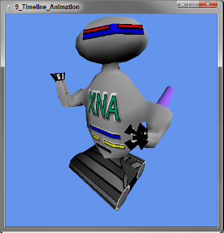
The current frame is calculated by multiplying the elapsed seconds by the frame rate and flooring the result. If the frame is past the end of the timeline, the animation is looped by starting at frame zero.
After loading the base bone transforms, I replace the transforms listed in the current frame (not all bones may be in the current frame). The remainder of the code is the same as before. The [W] and [S] keys work as before, showing how it's possible to blend animations into the final result.
This completes the Wrox Blox, and I hope it's given you a solid foundation of 3D XNA programming. If you journey deeper into 3D game development, you will probably want to use a game engine that can handle physics, lighting, animation, and more. Although you will be working at a higher level of abstraction, the fundamentals covered here remain the same, and your understanding of the basics will make it easier to use a game engine.
When you are ready to learn more about 3D game programming with XNA, I highly recommend joining the forums at http://creators.xna.com. These forums are a perfect place for a new game programmer to ask questions.