Chapter 7
Getting It Into the Game
Putting our model into the game requires a couple of steps. The first step is to begin refining the topology for the in-game mesh. Second, we need to generate the normal maps, texture maps, and any other maps that we might need.
There is a lot of debate on the topic of topology. What constitutes correct topology can be debated in all directions. However, there are a few concrete, essential concepts that you should understand. We’ll explore those in the next section, Topology Spectrum.
When we create the low resolution model we have two major concerns. We need to optimize our topology to show as much form with as few polygons as possible and we need to optimize the topology to be as animation friendly as possible.
There are a few important variables: the kind of rigging system used in the game and our expected level of realism. If there is any sort of dynamic rig on the model such as jiggle deformers than you need to heavily weight your topology to be all quads and as evenly distributed as possible.
If you want to emphasize lower resolutions, with more focus on the form of the model than how it moves in the game then you need to create more elaborate topology to describe the form of the model’s wrinkles. You can see an example of that in the Project: Topology and Clothing Folds section of this chapter.
So to restate the solution, your topology should allow you to accurately describe the form of your model up to the level that your rigging and animation setup can process.
The more specific your topology is, the harder it is for a more dynamic rig to create folds and wrinkles. In film work triangles and n-gons are avoided at all cost whenever a dynamic skin solve is used because triangles and n-gons do not behave as well as quads do. That said, games happen in real-time and cannot rely on a building full of computers to render one frame. In games, you have to make hard choices between how specific your topology is and how dynamic your rigging system is.
Project: Topology - Removing Interior Polygons
In this project we will adjust the topology of the jeans and the jacket to get them ready for viewing in Maya. Our goal at this point is not to create specific topology, but to get the model into Maya so we can begin to make realistic decisions about how to re-organize our topology.
1. Load your original model that you worked on in chapter 5. This model should have the hair sculpted with it. Immediately save this model as our in-game_SourceMesh.
2. Select the Jacket SubTool and go to the lowest subdivision level.
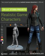
If you created the jacket like we did earlier in the book you will have a separate group for the outside of the jacket; the thickness of it and some of the inside is shown in Figure 7-1.
3. Press Ctrl+Shift and click on the outside of the jacket. Make sure to select all of the polygroups that belong to the outside of the mesh like Figure 7-2.
4. Go to the highest subdivision level for the jacket and click Tool ⇒ Masking ⇒ Mask All.
Figure 7-1: Jacket with Polygroups
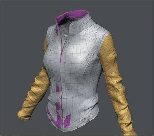
Figure 7-2: Jacket after removing inside polygroups
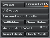
5. Go to the lowest subdivision level and press Tool ⇒ Geometry ⇒ Delete Hidden, as shown in Figure 7-3.
Figure 7-3: DelHidden button
6. Select the Jeans from the SubTool subpalette.
7. Press Ctrl+Shift and drag out a selection around the bottom of the jeans. Press Alt before releasing Ctrl+Shift to hide the area inside of the rectangle. Hide any other parts that you think should be deleted to create a base for our low resolution mesh. My example is shown in Figure 7-4.
8. Go to the highest subdivision level, mask all, then return to the lowest subdivision level and click Delete Hidden in the Geometry subpalette.
9. Repeat steps 6 through 8 for the belt and any other SubTools that need it.
10. As a final step make sure your SubTool has polygroups as indicated in Figure 7-5. We will use them later when we create UVs.
At this stage your jeans and jacket should be one-dimensional with no thickness. However, they should still have their entire subdivision history and polypainting.
Figure 7-4: Removing the bottom of the jeans
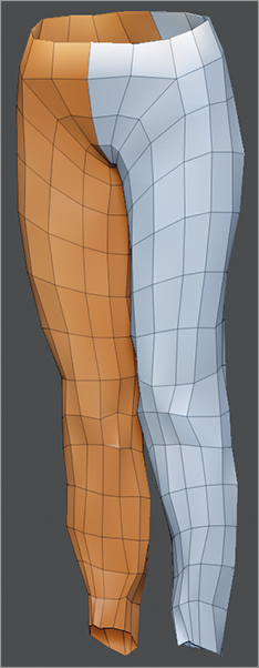
Figure 7-5: Your final Polygroups should look like this
Project: Topology - Combining Parts
The boots give us a chance to explore another way to work with the topology of our models. In this case, we will use the ZProject brush to project the vamp, the lower part of the boot, into the body of the boot.
1. Select the boot SubTool.
2. Click Rotate on the shelf and zoom in on the area around the lip of the boot. Press Ctrl and drag out a mask as shown in Figure 7-6.
3. Invert the mask by pressing Ctrl and clicking outside of the model.
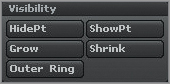
4. Click Visibility⇒ Hide Pt, as shown in Figure 7-7, to hide the masked areas. Make sure this corresponds to the lip of the boot. Adjust your selection as necessary.
5. Go to the highest subdivision level and click Mask All in the Masking subpalette. Then click Delete Hidden in the Geometry subpalette.
Figure 7-6: Using Topological Masking on the boot
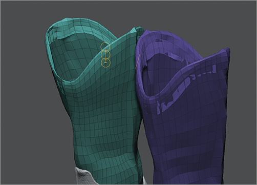
Figure 7-7: Hide Pt button
6. Make sure that the boot and the vamp are both visible in the SubTool palette and then select the ZProject brush.
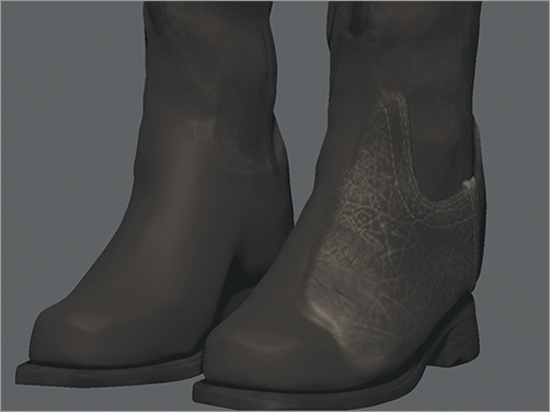
7. Click RGB and Zadd on the shelf. Make sure that symmetry is off. ZProject doesn’t work well with symmetry. Then brush along the surface of the model as shown in Figure 7-8. Only brush the areas that are facing you. Avoid brush along the sides as this will create artifacts and damage your topology.
Figure 7-8: Projecting the vamp into the boot
8. To access the inside of the boots you’ll have to hide the left and the right side respectively. Use Ctrl+Shift and drag out a selection for each SubTool. Then use ZProject to project the details as illustrated in Figure 7-9.
Figure 7-9: Projecting the inside of the vamp into the boot
9. Once the vamp is projected into the boot you can delete the SubTool by clicking Delete in the SubTool subpalette.
10. If you have not saved your model by now you are living dangerously. This is just a friendly reminder. Save now, save often, and save again in 5 minutes.
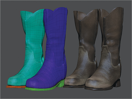
11. As a final step make sure your SubTool has polygroups as indicated in Figure 7-10. We will use them later when we create UVs.
Figure 7-10: Final boot
Let’s add the holster we created in Chapter 6. This will require a few steps and we want to make sure that we get everything appended to our in-game-SourceMesh as cleanly as possible. In the very next project we’ll adjust the topology to be useable in the game engine.
Follow the steps below to begin.
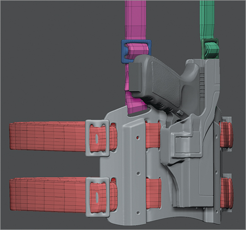
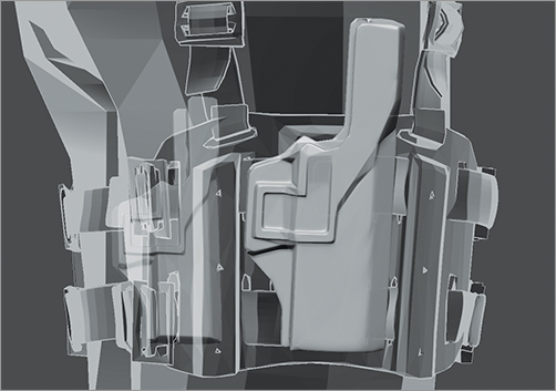
1. Load the pistol we created in Chapter 6 (shown in Figure 7-11).
Figure 7-11: Our holster with platform, straps and buckle
2. Select the pistol and select the Strap_top subtool from it.
3. Select the in-game_SourceMesh and append the Strap_Top.
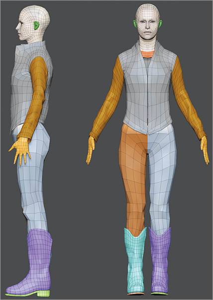
4. Repeat steps 3 and 4 until you have appended the strap_bottom, hip straps, buckles, holster, platform, and holster release. Don’t worry about the pistol itself. We can import it later as its own model. Figure 7-12 illustrates our progress.
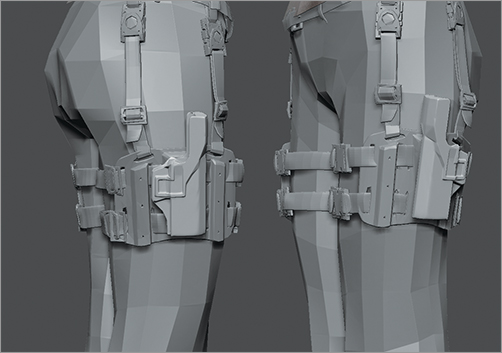
5. Once the parts are appended, it’s time to position them. Use Transpose Master to rotate, scale and move them into place. When done, your model should look like Figure 7-13.
Figure 7-12: Holster parts appended to in-games_SourceMesh
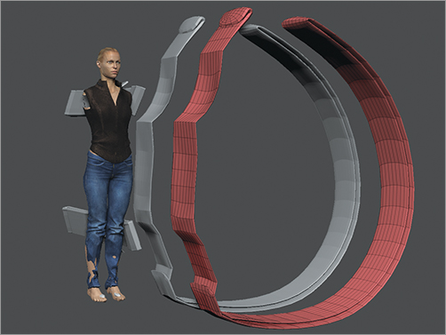
Figure 7-13: Holster after being positioned
6. Use the Move Up and Move Down arrows in the SubTool list to position Strap_Top, Strap_Bottom and Hip_Strap on top of each other.
7. Select Straps_Top. Open the Geometry sub-palette and check how many subdivision levels it has. If it has three levels, set it all the way to subdivision level 3.
8. Select Straps_Bottom and open the Geometry sub-palette. If it has more than 3 subdivision levels, then set it to SDiv 3 and click Del Higher in the Geometry sub-palette. It if has less than, divide it till it has at least three levels. The goal here is to make sure that all of the straps have the same number of subdivision levels and that they are at the exact same subdivision level.
9. Select Straps_Top and click Merge Down in the SubTool sub-palette. This is not an undoable operation so you want to make sure that each strap is at the same subdivision level and that they have the same number of levels. You might consider saving your model before doing this step in case something happens.
10. Use the Move Up and Move Down arrows in the SubTool list to position all of the buckles on top of each other. Then click Merge Down to combine them, as well.
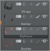
11. At this point you should have 4 SubTools, shown in Figure 7-14, that belong to the holster: straps, buckles, platform and holster. Double check this and make sure before beginning.
Figure 7-14: Our SubTool list
Project: Topology - Decimation Master & Polypainting
When we created the platform and the holster we used Mesh Extraction from a fairly high polygon mesh. This means that these SubTools have way too many polygons to be used in the game.
In our specific case, we are not going to retopologize these SubTools. Instead, we are going to use Decimation Master. Now, depending on your game pipeline, you may have to retopologize it. My interest, though, is to show you another way that you can keep your polygon count low and still retain all of its form.
There is one big roadblock standing in our way though: our Polypainting. How do we transfer the Polypainting from our design sculpt to our decimated topology? Well, I’m glad you asked.
The short answer is that we will use the ZProject brush but follow the steps below to see how it ends.
1. Select the Holster, seen in Figure 7-15 from the SubTool list.
Figure 7-15: The Holster
2. Click Duplicate in the SubTool sub-palette.
3. Click Pre-Process Current in the Decimation subpalette of the ZPlugins palette, as shown in Figure 7-16. Note, you only need to process the current selection for now.
Figure 7-16: Decimation Master
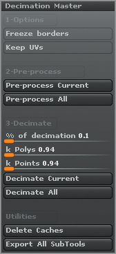
4. Set % of Decimation to .1% click Decimate Current. Hover over the Tool palette thumbnail and check how many polygons it is. You may need to set Decimation % as low as .05%. If you need to set it lower, simply change the number in the Decimation % and click Decimate Current again.
5. Click Divide, in the Geometry sub-palette, several times. We want our decimated model and our original holster to be roughly the same number of polygons.
6. Select the ZProject brush and make sure that RGB is on and Zadd is off on the shelf. You may also want to hide all the other SubTools. Then just brush along the surface to transfer the details the painting.
Now, you might be wondering how you will be able to UV the holster with this type of topology. Well, for the holster there is no problem. We’ll be able to create UVs using UV Master and get a decent amount of control over it. The Platform SubTool, however, is another story. It has too many openings for UV Master to function correctly so we’ll look at how we retopologize it and create the UVs for it in the Project: UVs, Topology and the Platform section.
You’re going to hate me. I almost hate myself doing this step but it has to happen. We have to convert our beautiful sculpted hair into hair that can sit in our game engine. That said, though, this is a great opportunity to relook at the planes of hair and get a fresh perspective on how to create curls.
To begin follow the steps below.
1. Load hairNet.obj from Chapter 8’s resource folder in the resource DVD. This strip will be roughly positioned for an 8 head character so you might have to adjust its placement. Figures 7-17 and 7-18 illustrate our placement.
Figure 7-17: Polygon hair groups
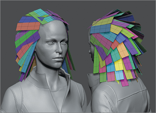
Figure 7-18: More polygon hair groups
2. Click Autogroups in the Polygroups subpalette.
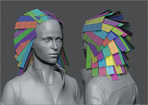
3. Use Move Elastic and Transpose’s Move and Rotate to position the hair. Create a wavy quality that matches your design sculpt of the hair. Figure 7-19 shows our progress.
4. Try not to get too specific as that will slow you down and make this even more painful. You can adjust further once you have the general shape of the model’s hair. When you’re done your hair should resemble Figure 7-20. Notice how the groups of hair interpenetrate each other. Let’s fix that.
Figure 7-19: Progress with hair
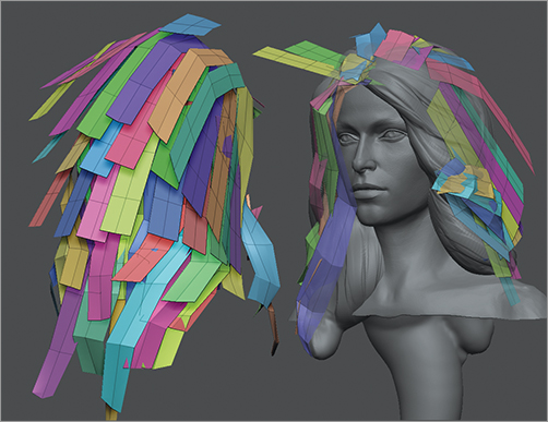
Figure 7-20: First pass on hair
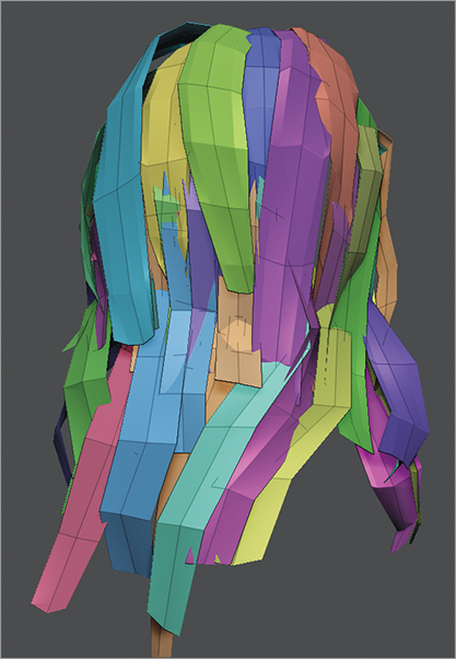
5. Let’s make sure that each layer lays on top of the layer below it. To do that we need to make sure that each layer has its own polygroup or SubTool. I like to use SubTools because it isolates the different layers of hair. Press Ctrl+Shift and click on one of the strands along the bottom. Then press Ctrl+Shift and click and drag outside of the model to invert that. Then press Ctrl+Shift and click the remaining groups of hair along the bottom row.
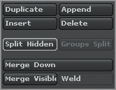
6. Click Split Hidden, as shown in Figure 7-21, in the SubTool subpalette to separate the hidden parts of the model into their own SubTool.
Figure 7-21: Split Hidden
7. Repeat steps 9 and 10 for each layer of hair groups.
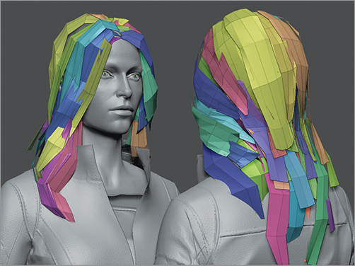
8. Using Move Elastic tuck the tops of the hair underneath the layer above them and the bottom of the groups above them. Figure 7-22 demonstrates our finished hair.
9. Select the highest hair grouping in the SubTool list and then merge it all back together using Merge Down.
Figure 7-22: Final hair
Project: Create UVs using UV Master
Once you have the Polygroups created we are ready to create the UVs. The groups are an essential part of UV creation because they create the different islands.
Make sure that you have UVMaster installed and follow the steps below to continue.
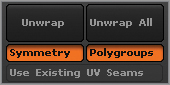
1. In the UVMaster subpalette, shown in Figure 7-23, of the ZPlugins palette click Polygroups.
Figure 7-23: UV Master plugin

2. Select the jacket in the SubTool subpalette and set it to the lowest subdivision.
3. Click Work on Clone in the subpalette so we can start to get more detailed with our model.
4. Click Polygroups directly under the Unwrap All button as shown in Figure 7-24.
Figure 7-24: Polygroups button
5. Click Unwrap, in the UV Master subpalette, to see what UVMaster will create by itself.
6. Click Flatten in the UV Master sub-palette to see the UV layout. Most likely you will have to adjust these but it’s worth a try to see if UV Master got it right from the start.
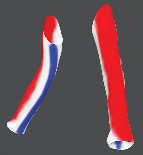
7. Click Enable Control Painting and then click Attract. Paint the model where you would like the seam for the UVs to show up. The blue lines in Figure 7-25 show where the seams will be.
8. Click Protect, under the Enable Control Painting button, and paint the model red, as shown in Figure 7-25, wherever you do not want a seam to appear.
Figure 7-25: Control painting for jacket
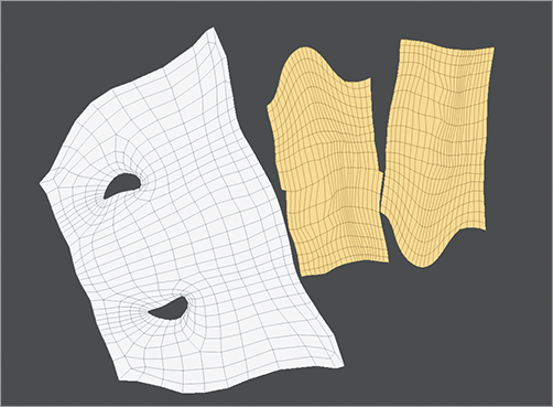
9. Click Unwrap to create the UVs for your model again. Then click Flatten, towards the bottom of the subpalette, to see how your UVs look. Figure 7-26 demonstrates our final UV Layout. If they look fine, then it’s time to transfer them back to the mesh. If they do not look good, then make sure that you have the area correctly painted and repaint if necessary.
10. Click CopyUVs.
11. Select the original jacket from the SubTool sub-palette of our sculpted model and click PasteUVs in the UV Master sub-palette.
12. That completes our UV creation for the jacket. Repeat this for each of the SubTools that require UVs. Don’t worry about the Platform, though, we’ll look at how to work with it in the next section.
Figure 7-26: Final Uvs
Project: UVs, Topology, and the Platform
The platform we created in Chapter 6 has issues with UV Master. These issues give us a chance to showcase a really cool feature of UV Master: Keep UVs. The problem with the platform is that there are too many holes in it. UV Master doesn’t really know what to do with them. To fix the problem we have to use our PolyGroups from the original sculpt to help us create the UVs.
Follow the steps below to continue.
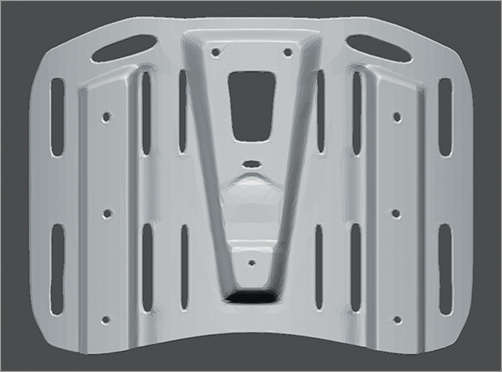
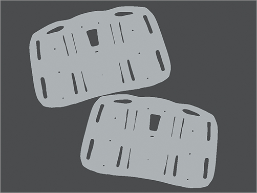
1. Select the Platform, seen in Figure 7-27 from the SubTool list.
Figure 7-27: the Platform
2. Turn on PolyFrame and make sure you still have the groups from the front and back of the platform. In this case we are going to keep the back of the platform. It’s entirely reasonable for you to delete the back for your in-game mesh.
3. Click Polygroups in the UV Master sub-palette and then click Unwrap.
4. Click Morph UV in the UV Map sub-palette of the Tool palette and make sure that your UVs look like Figure 7-28.
Figure 7-28: Our UV Layout
5. Set SDiv, in the Geometry sub-palette, to the highest subdivision level.
6. Click New from Polypaint in the Texture sub-palette to create a texture map with all your Polypainting on it.
7. Click Keep UVs (Figure 7-29) in the Decimation Master sub-palette and then click Pre-process Current.
Figure 7-29: Decimation Master interface
8. Set % of Decimation very low. Remarkable, a number as low as .1 still provides decent results and keeps your UVs.
9. Click Decimate Current.
10. When your model is at the resolution level you like click Export from the Tool palette and navigate to where you would like to save the low-resolution in-game mesh.
11. In the Texture sub-palette click Clone to send the texture to the Texture palette.
12. From the Texture palette click Export to save it alongside your low-resolution OBJ file.
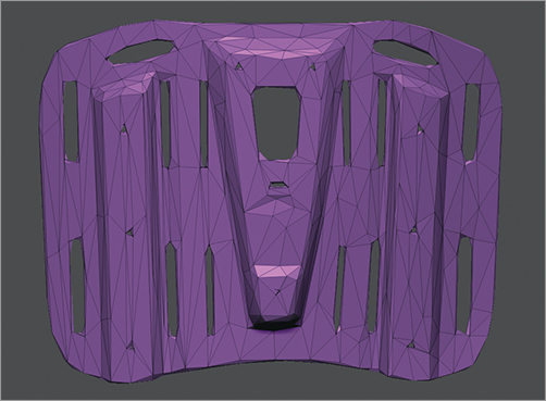
Figure 7-30: Decimated Platform
With our new topology and new UVs we are ready to generate our texture maps, normal maps, cavity maps, and bump maps.
1. Make sure you have MME loaded. If not, visit Pixologic’s Download Center and install it before continuing.
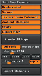
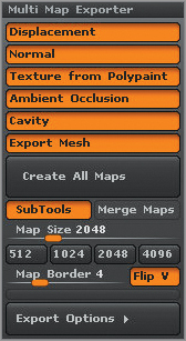
2. Open the Multi Map Exporter subpalette in the Zplugins palette, shown in Figure 7-31. Click all of the maps so that we get everything all at once.
Figure 7-31: Multi Map Exporter palette
3. Click SubTools in the MME subpalette. It is located directly below the Create All Maps button.
4. Click Export Options to open its controls.
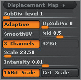
5. Click Displacement Maps and then click Adaptive, 3 Channel, and 16 bit Scale. Then click Get Scale and make a note of the number in the Scale slider. Figure 7-32 illustrates our settings.
Figure 7-32: Displacement Map settings
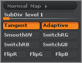
6. Click the Normal Map button to open its controls. Then click Tangent and Adaptive. For your game engine you may need to also click SwitchRB or FlipG. For now, leave them at defaults. We’ll switch or flip only if necessary. Figure 7-33 illustrates our settings.
7. We’ll leave Ambient Occlusion and Cavity at their default settings for now.
Figure 7-33: Normal Map settings
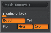
8. Click Mesh Export to open its controls. Then click MRG to make sure that your model’s vertices stay merged. Figure 7-34 illustrates our settings.
Figure 7-34: Mesh Export settings
9. Finally, when all done with the settings click Create All Maps towards the top of the subpalette. Set a folder to store them in and click OK.
Creating the Specular Map
The last map we need to create, we can’t create in ZBrush: it’s the Specularity map. This is a very important map that really helps us create the illusion of reality.
Follow the steps below to create your specular map. Note, you’ll likely have to tweak this after previewing the map in the next project, Viewing the Game Model.
1. In Photoshop, copy the Texture map into a new document. Then desaturate it entirely by pressing Ctrl+Shift+U.
2. Copy the cavity map into the new document and set its blending mode to Multiply.
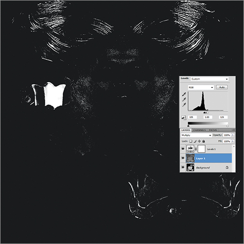
3. Create a Levels or Curves adjustment layer and adjust its settings to clamp the light and dark values down and increase the contrast.
4. Save the document as both a .PSD file and a .TGA file. You want to make sure to save a .PSD file so you can alter the document later after previewing it in the game engine.
Figure 7-35 demonstrates our final spec map for the face along with the layer settings. Repeat this as necessary for the rest of the maps.
Figure 7-35: Specular map with layers and adjustments
Project: Setting Up Model in Maya
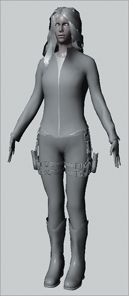
To see how our model is doing and where we’ll need to redo the topology we want to preview the model with its normal map in a 3D application like Maya.
1. In Maya, click Import in the File menu and import each of the low resolution meshes, demonstrated in Figure 7-36, that ZBrush’s MME exported.
2. Open Hypershade and create a new Blinn. In the Hypershade window create a Blinn and drag it to the jacket in the viewport.
Figure 7-36: Low Resolution objects in Maya
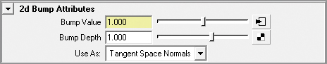
3. Open the attribute editor by double-clicking the Blinn or press Ctrl+A.
4. Click the Bump Mapping node. Set the Use As text box to Tangent Space Normals as shown in Figure 7-37.
5. Choose File from the pop-up and then click the arrow next to Bump Value to go to the file node. Click the folder next to Image Name and navigate to the normal map for the jacket.
Figure 7-37: Bump Map node
6. Click the checker next to the Color node. Choose File from the pop-up. Click the checker next to the Image Name folder and navigate to the color map.
7. Repeat step 6 for the specular map as well.
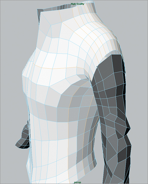
8. Press 6 on your keyboard and then click High Quality Rendering in the Renderer menu of the viewport. You should now see the normal map and texture map on the jacket.
9. Repeat steps 2 through 7 for the remaining parts of the model. Figure 7-38 demonstrates the model with all of the maps set up.
Figure 7-38: Model in Maya with all her maps
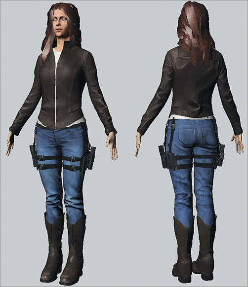
When you have the entire mesh in Maya with the normal maps you can plainly see the limitations of them; they only work within the interior of the model. They cannot create outside contours. Now we need to decide if we will “hard-code” the clothing folds into our mesh or not.
If we only need to reflow the topology a bit we can refer back to the Project: Topology section in chapter 3. Towards the end of that chapter there are about three or four steps where we import different topology into the lowest resolution and use the Morph brush to fix up areas.
If, though, we plan to hard code the topology then we need to talk for a moment about how to do that and how our topology might look. We’ll look into that in the next section, Project: Topology and Clothing Folds.
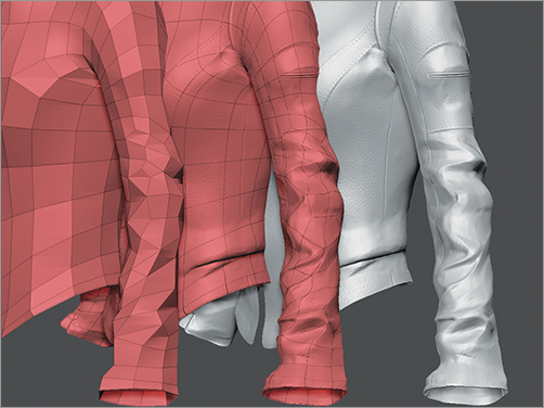
Project: Topology-Optimized for Form
Topology that describes folds invariably has triangles and n-gons in it. Use it only when you need the absolute highest amount of optimization in your model as it causes problems both when you sculpt and when you use more advanced rigs.
Follow the steps below to re-topologize the jacket.
1. Select the jacket from the SubTool list and click Clone in the Tool palette.
2. Select the cloned jacket. Then set the color swatch to white and click Color⇒ Fill Object.
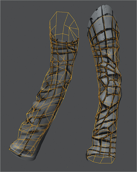
3. Select the Standard brush and set the color to black. Then start by defining the halfway points along the front and side of the arm as seen in Figure 7-39.
Figure 7-39: Dividing the sides of the model
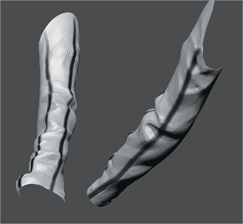
4. Next start to define the high points and the low points of the major wrinkles. You’ll want to make sure that you define both the high points and the low points at the same time. Look for the blue lines in Figure 7-40 to see the main flow lines.
5. Use triangle-shaped quads to create the corner of the folds. Figure 7-40 illustrates these polygon faces in red.
6. In the back of the arm you can see where you can use triangles to describe the diamond shape of compression folds as shown in Figure 7-40 and highlighted in green.
7. When you have the major folds outline, it’s time to integrate it with the upper part of the arm and to final topology. This step will take time and it does take patience to become profient with it.
Figure 7-40: Topology Lines
8. Once you have the arm topology painted its time to start re-topologizing. Select a ZSphere from the Tool palette.
9. In the rigging tab click Select Mesh and select the jacket with the topology lines painted on it.
10. Click Edit Topology in the Topology subpalette.
11. Make sure that Symmetry is on and start to create the topology for the arm jacket as shown in Figure 7-41. Use the PolyPainting as your guide.
12. When done, set Density to 1 in the Adaptive Skin subpalette and click Make Adaptive Mesh.
13. We’ve only created the arms, but that is all we really wanted to re-topologize. Export the arm jackets as OBJs. Make sure the MRG is on in the Export sub-palette.
14. In Maya or another 3D application import the re-topologized arm. Also, import the low resolution jacket that MME exported.
Figure 7-41: Final topology using ZSphere’s Topology feature
15. Select the jacket, right-click on it and choose faces. Delete the faces that correspond to the arms that we have retopologized.
16. Select both objects, the arms, and the jacket, and click Combine in the Mesh menu.
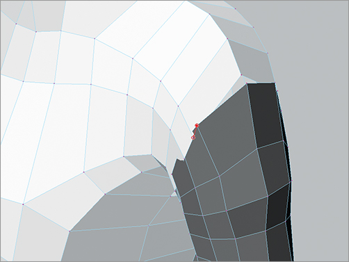
17. Click the Select Edge Loops tool from the Select menu. Press Shift to select multiple edge loops and select all the edge loops that are not needed for the arm or do not have corresponding edge loops in the arm of the jacket as demonstrated in Figure 7-42.
Figure 7-42: Deleting extra edge loops
18. Click Delete Edge/Vertice in the Edit Mesh menu to remove them.
19. Select the Merge Vertice Tool in the Edit Mesh menu and go one-by-one around the arm to merge the vertices of the arm to the jacket, as shown in Figure 7-43.
20. Check the mesh to make sure that both arms attached correctly. You might need to conform the normal or delete extraneous edge loops. Sometimes, I have to delete some polygon faces and recreate them using Maya’s Append to Polygon tool.
21. Select the jacket and click Export Selected in the File menu.
Figure 7-43: Merging Vertices
Project: Importing Jacket’s Reflowed Topology
I want to take a moment to look at a few tricks and tips for importing the jackets new topology into its original sculpt. Follow the steps below to get started.
1. In ZBrush, select a PolyMesh3D star and import your jacket’s reflowed topology. It’s important that you select the PolyMesh3Dtool, shown in Figure 7-44, to do this.
Figure 7-44: Polymesh3D

2. Click Divide once in the geometry sub-palette.
3. Go to the lowest resolution and click Export. Let’s call this jacketReflowedSmoothed.OBJ.
4. Select the jacket SubTool in our in-game_SourceMesh and go to the lowest subdivision level.
5. Click Import and navigate to the jacketReflowedSmoothed.OBJ.
6. At the prompt, click Yes to reproject all of the higher frequency details.
7. Click Switch in the Morph Target sub-palette to return the mesh to its preprojected state.
8. Select the Morph brush and brush the projection back in. Watch for areas where the polygons go astray. Those are areas you’ll have to resculpt. Figure 7-45 illustrates the results of our re-projection.
9. One downside to this is that it destroys your UVs. However, UV Master makes it very easy to create them. I recommend that you recreate the Polygroups along the arms of the jacket and then click Unwrap in the UV Master sub-palette. You can, however, just click Unwrap and let UV Master sort it all out for you.
10. Once your UVs are created then hide all of the other SubTools in the list. You can do this by clicking the eye icon of the jacket. If you already have objects hidden then you’ll have to click it twice.
11. Make sure SubTools, the Multi Map Exporter, is orange. Then click Create All Maps to recreate the maps.
Figure 7-45: Final topology for jacket
Project: Getting Model into Marmoset
Once you have your model all set up in Maya it’s time to export directly into a game engine. There are a lot of game engines out there but most of them take more time than we have in this section to get into.
Marmoset, however, is a game engine for us sculptors. It is designed for game artists who want to quickly see what their model will look like in a game engine.
I would like to thank Mark Dedecker, freelance character artists, for vetting this section and providing its framework. Note, you’ll want to do this step only after getting the model into Maya as it does require the use of a Maya plugin.
So, to get into Marmoset follow the steps below.
1. First we have to install Marmoset. There is a 30 day trial on the DVD that comes with this book or you can download from http://www.8monkeylabs.com/. Double click the installer executable and follow the prompts.
2. We’re not done with just that though. Next you have to install the Maya plugin. Make sure to read Marmoset’s documentation to see the how and the where.
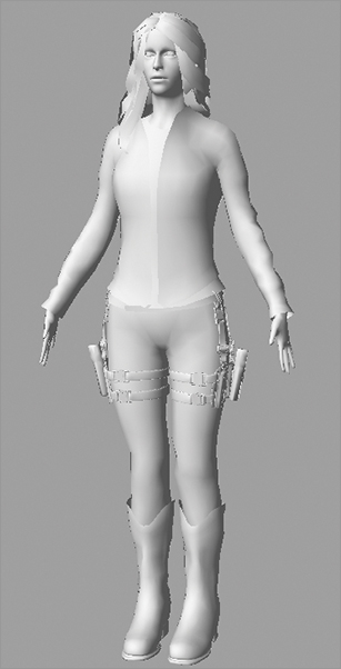
3. After you’ve restarted Maya, open the Maya scene file that you had when you finished from the Project: Setting Up Model In Maya section. However, if you don’t have that scene file you can import all the OBJ files into a new scene file. Make sure, though, that you smooth the normals of all the objects before you continue. To smooth the normals, click Normals: Soften Edge. Your model should look like Figure 7-46, at this stage.
Figure 7-46: Smoothed Normals in Maya
4. The final step before exporting is to rename the separate parts of your model so that they are easily identifiable in marmoset. Note, Marmoset calls these separate parts “chunks.”
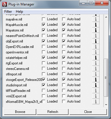
5. In the Plug-in Manager, shown in Figure 7-47, under Window: Settings/Preference, load stoogeExport and click Auto-load so it starts with Maya. If you do not have the plugin listed here, it has not been installed. Check the Marmoset documentation and reinstall the export plugin.
Figure 7-47: Plugin Manager
6. Select all of the parts that you want to export and then type “stooge” in the Mel script line shown in Figure 7-48. This will bring up Marmosets export window.
Figure 7-48: Maya’s Mel window
7. Leave everything at its default unless you already know what you want and click Export. Choose a location to save the new .mesh file. It can take a bit of time to export so be patient and wait for it to finish.
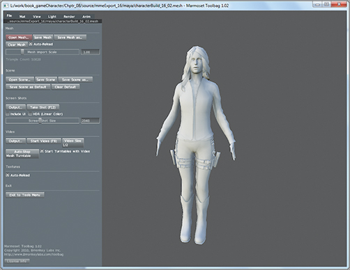
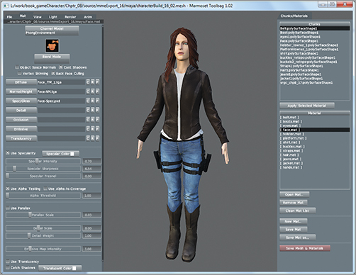
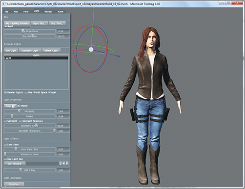
8. Open Marmoset and click Open Mesh in the File menu. Navigate to the .mesh file you saved in step 7. In Marmoset your model should look like Figure 7-49.
Figure 7-49: Our model in marmoset
9. Navigation in Marmoset mirrors Maya. Rotate the model around and check for any flipped or reversed normals. If you see any, you’ll have to go back to Maya and fix them.
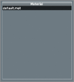
10. Open Mat menu. On the right hand side there is a material list as shown in Figure 7-50. Only a default mat is created at this point.
Click New Mat, in the bottom right of the interface, to create a new material and choose the directory you want to save it in and save it as FaceMat.
Figure 7-50: Material List
11. Select the face chunk from the Chunks list, shown in Figure 7-51. Select the FaceMat material in the Material list. Then, click Apply Selected Material to assign it the new face material to the face.
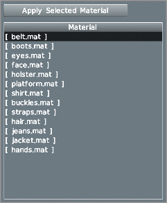
12. Repeat steps 10 and 11 for each chunk until you have a separate material for each part, as shown in Figure 7-52. When you’re done, click Save Mesh & Materials in the bottom right hand corner of the interface.
Figure 7-51: Chunks List
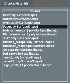
Figure 7-52: Material List with All Materials
13. Select the FaceMat material from the Material list. On the left click Diffuse, seen in Figure 7-53, and navigate to where ZBrush exported your texture map. Keep in mind it will have a suffix of “-TM”.
14. Click Normal /Height and navigate to the normal map for the face. Click Spec/Gloss and find the face’s specular map we made ealier. You can experiment with the other maps but this covers our immediate needs.
15. To turn on specularity you need to click Use Specularity, shown in Figure 7-54, for each material that you want to have it. If you don’t have a specular map you can fake it by assigning the color map into the Specular/ Gloss channel. Adjust Specular Intensity as I find its default settings a bit high sometimes.
Figure 7-53: Diffuse Settings
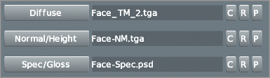
Figure 7-54: Specularity settings
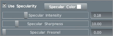
16. Check your specularity by holding down the shift key and LMB and slide the mouse around to move the light.
17. Repeat steps 13 through 15 for each material in the Material list. Once your done make sure to click Save Mesh & Material. Figure 7-55 shows what our first pass on the materials should look like.
Figure 7-55: Our model with materials setup
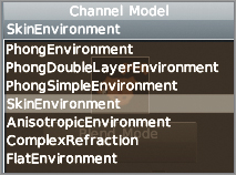
18. Now, we want to change the type of material for the face and any other skin. In our case, we change the material for the hands and head. Select the FaceMat material again and click Channel Mode in the Mat menu. Select Skin Environment from the list as seen in Figure 7-56.
Figure 7-56: Channel Mode
19. Increase Scattering to get more of the Subdermis Color to show through. Adjust Subdermis Depth to limit some of the effects of Scattering. Scatter Smoothing can be used to soften the lighting and shadows just as real world SSS does.
My settings are as follows:
Scattering = . 7
Subdermis Depth = .6
Scatter Smoothing = .8
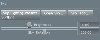
20. Select the Light menu. Click Sky Lighting Presets and select Sunlight (Figure 7-57). Adjust Sky Brightness to increase or decrease the light intensity.
Figure 7-57: Sky settings
21. To add a rim light, click Add Light. Use the manipulator to position the light behind the model as shown in Figure 7-58.
22. Click the Color swatch to change the color from purple to white or whichever color you choose.
Figure 7-58: Adding a rim light
23. In the File menu click Save Scene. Then open the Mat menu and save the Materials. This is just a safety check. I’m sure you’ve been saving all along.
24. Now we are ready to render a turn table. Position your model in the view finder just as you want it for your turntable.
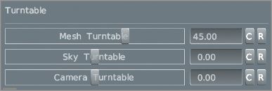
25. Open the View menu, shown in Figure 7-59. Set Mesh Turntable to 45.
Figure 7-59: Turntable settings
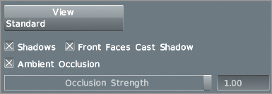
26. With the model still rotating, open the Render menu and click Ambient Occlusion (Figure 7-60).
Figure 7-60: Ambient Occlusion settings
27. In the File menu, while the model is still rotating, click the Output (Figure 7-61) and navigate to where you want this to be exported to.
Figure 7-61: Output settings
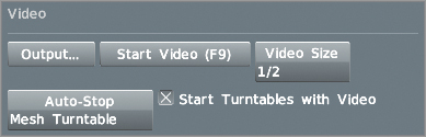
28. Click Video Size and choose whether you want your turntable’s resolution to be half of the screen, a quarter of the screen, or full screen.
29. Click Auto-Stop and select Mesh Turntable from the list.
30. Press the SPACEBAR to clear the UI from the screen and press F9 on the keyboard to begin recording. A small, red video icon will flash on the bottom right of the screen as seen in Figure 7-62. It will continue to flash until it has completed one revolution. Once it’s done, you can press “t” on the keyboard to pause the turntable.
Figure 7-62: Recording Icon

31. Navigate to where your file was saved and double click it to open it. Make sure you have all of the model rendered and it is positioned as you want it. There is more you can do but at this point you’ve rendered it out.
At this stage our model is in the game and we have a turntable. We are almost completely done with the model and you deserve a round of applause for your efforts so far. Keep your spirits up. In the next section we will look at creating a dynamic pose for our model. We’ll also learn how to use ZBrush’s new rendering and animation system.