
Chapter 2
Special Project—Creating Accessories for a Bust
I used several techniques to create the bust for this exercise to have him come alive. Before diving into ZBrush, though, I took a step back and thought about how to create each SubTool for this bust. I looked for simple approaches to create some common accessories.
This chapter takes you through the process of creating pieces for the character in my bust, beginning with how I created the ZMan logo that is stitched into the fabric of the hoody.
- Creating the ZMan logo
- Creating the zipper
- Creating the stand
- Creating a skin texture
First, you need to find a black-and-white image of the Pixologic ZMan logo. Follow along with creating the ZMan logo by downloading the texture named ZMan.psd off the DVD in the assets folder of Chapter 2. You can see the ZMan.psd image in Figure 2-1.
Figure 2-1: ZMan logo as a texture

Off we go. Follow these steps to import your ZMan logo into ZBrush:
1. Click the Import button in the Texture palette to import the logo as a texture. The texture appears on the left side of the interface, in the texture slot. ZBrush has assigned the logo to your current brush, and any strokes you create will use the shape of the texture.
2. Select Plane3D in the Tool palette.
3. By default, the Plane3D tool is a parametric 3D object: the sculpting brushes do not affect it. To convert it into a 3D mesh that you can sculpt on, click the Make PolyMesh3D button at the top of your Tool palette.
4. Now let’s subdivide the polygons of the plane so that the brush strokes appear smooth on the surface of the plane. Choose Tool Geometry, deactivate the Smt button next to Divide, and divide the mesh to level 5 (see Figure 2-2).
Figure 2-2: Turn off Smt in the Geometry subpalette to disable smoothness when dividing.
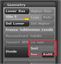
The Smt button activates smoothness when you divide in ZBrush. With Smt off, the corners of the plane will not become rounded. This is a great way to subdivide a mesh without affecting the overall shape of the object.
5. Click the large icon under the Tool Texture Map subpalette and select the ZMan logo, as shown in Figure 2-3. This action applies the logo as a texture to the plane.
Figure 2-3: Applying the ZMan logo to the plane

6. Under the Tool Masking subpalette, click the Mask by Intensity button. At first, nothing seems to happen.
7. Turn off the ZMan logo in the Texture Map subpalette. Your result should be the same as Figure 2-4. The logo has been applied to the plane as a mask, as indicated by the gray color on the plane.
Figure 2-4: The ZMan logo is applied as a mask to the plane.

8. At the bottom of the SubTool subpalette, change E Smt and S Smt to 1 and the Thick slider to Figure 2-5. Click the Accept button so ZBrush will create the logo.
Figure 2-5: Extracting the mask to create the logo

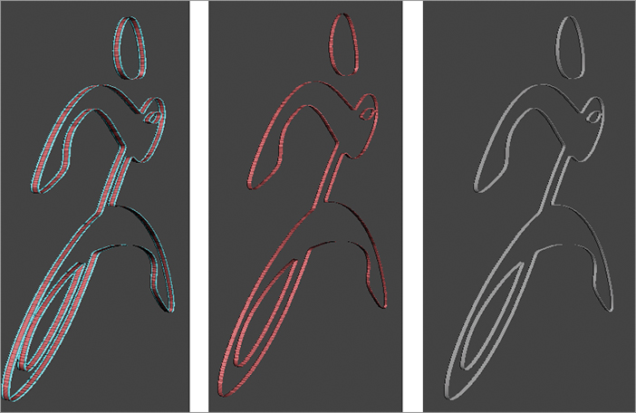
Notice that when you complete an extraction, ZBrush assigns a polygroup to the back, middle, and front portions of the mesh (see Figure 2-6).
Figure 2-6: Notice the back, middle, and front of thelogo have different polygroups.

9. To activate your polygroups, click the PolyF icon (or press Shift+F to activate Polyframe mode).
10. Display only the middle section by Ctrl+Shift-clicking the middle section to isolate the visibility, as shown in Figure 2-7.
Figure 2-7: Inner polygroup selected

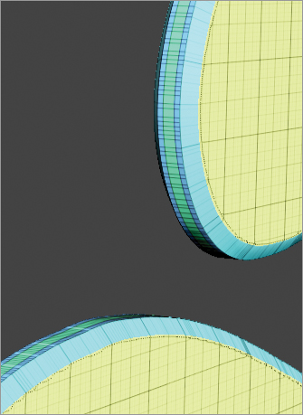
11. Click the Edge Loop button in the Tool Geometry subpalette to add an edge loop of polygons on either side of the visible section, as shown in the left image of Figure 2-8.
Figure 2-8: Inner polygroup added by clicking the Edge Loop button (left), selection reduced to the innermost polygroup (middle), and inner polygroup masked (right)
12. In the Tool Visibility subpalette, use the Shrink button (or Ctrl+Shift+S) to reduce the selection so that only the inner polygroup is visible.
13. With just the inner polygroup visible, mask the whole mesh off by clicking the MaskAll button in the Tool Masking subpalette (or by holding Ctrl while clicking anywhere in the empty space), as shown in the middle image of Figure 2-8.
14. Make the whole mesh visible by holding Ctrl+Shift while clicking on an open space, as shown on the right in Figure 2-9.
15. Hold Ctrl and click anywhere on the document to invert the masking (see Figure 2-9).
Figure 2-9: Mesh completely visible with inner polygroup masked (left), and mask inverted after the whole mesh is visible (right)
16. You can now bevel the surface by inflating the unmasked portion. To do this, expand the Tool Deformation subpalette and move the Inflate slider to the right. Figure 2-10 shows a nice bevel along the logo.
Figure 2-10: Bevel along the mesh

17. Repeat the process with the new inner polygroup to create another edge loop, as shown in Figure 2-11.
Figure 2-11: New edge loop
18. Mask off the new inner polygroup and then invert it as you did in the previous steps (see Figure 2-12) to repeat the inflating of the border.
Figure 2-12: The second inner polygroup exposed with the rest of the mesh masked off

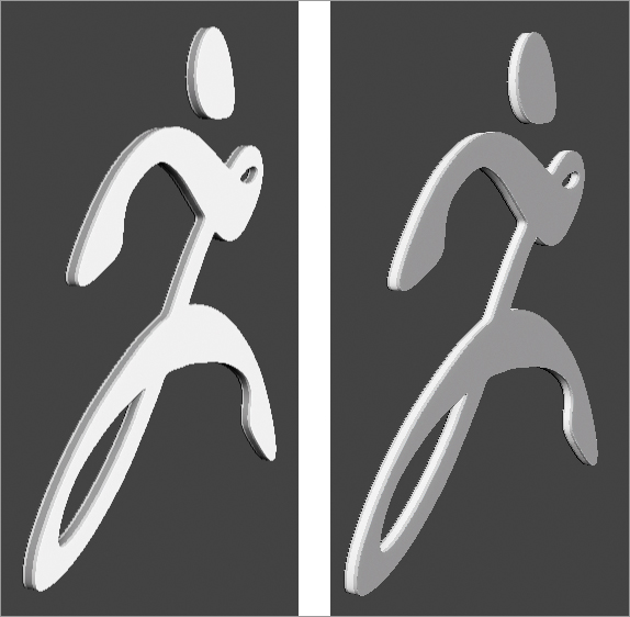
19. Finally, inflate the mesh again with the Deformation Inflate slider.
The final result for the logo is shown in Figure 2-13.
Figure 2-13: Finished ZMan logo

With this simple technique, you can create a base mesh. You can find a perfect example of another way to use this technique at www.zbrushcentral.com/showthread.php?t=095181. When you have a moment, watch the videos on how the motorcycle was constructed.
Placing the ZMan Logo on the Hoody
Now you need to position the ZMan logo tool to match the curve of the hoody. The MatchMaker brush makes this task easy. With one quick stroke, the logo can match the shape of any surface behind it. Load the Hoody.ZTL from the Chapter 2 Assets folder. Make sure to have the hoody in Edit mode. This hoody was sculpted from the PolySphere that is shipped with ZBrush.
1. Append the logo as a SubTool to the hoody and then position the logo in place (see Figure 2-14).
Figure 2-14: Logo positioned in place after appending it

2. The logo is too large, so you must adjust the size by clicking the Scale Mode button (hot key = R) above the canvas. Now you can use the Transpose tool to make the logo fit as shown in Figure 2-15.
Figure 2-15: Scale of ZMan logo changed to fit in position
You want to make the logo match the surface of the hoody so it looks more like a patch sewn on the fabric (see Figure 2-16). This is where the magic happens with the MatchMaker brush: it uses the Z-depth information of the canvas to deform the surface.
Figure 2-16: Logo flatness compared to the curve of the hoody

3. Turn off the Persp button on the right shelf to disable perspective so it does not affect the deformation created by the brush.
4. Position the camera to look straight ahead at the logo in front of the hoody (see Figure 2-17).
Figure 2-17: Position the camera to look straight ahead.

5. In this position, you can switch to the MatchMaker brush quickly by pressing B, M, and then M again. With one stroke, the logo will match the hoody (see Figure 2-18).
Figure 2-18: ZMan logo matched to the shape of the hoody

6. Now you must move the logo closer to the hoody. The camera must not move after using MatchMaker, or the logo will become misaligned with the hoody. You must switch to Move mode at the top of the interface to move the logo freely.
7. Hold the Alt key while Move mode is active. Move mode lets you move any subtool without drawing out the Transpose line if you click the subtool while holding the Alt key.
8. To move the logo right up next to the hoody, hold the Alt key in Move mode, click the logo, and then let go of Alt without letting go of the Left Mouse button or taking the Wacom pen off the tablet or Cintiq. Now you can move your mouse or pen up and down, which will move the logo in Z-depth. You can see my result in Figure 2-19.
Figure 2-19: ZMan logo in position on the hoody

MatchMaker will match any geometry lying behind the target mesh even if it’s a separate subtool. Be sure to keep the geometry mesh (for example, the ZMan logo) smaller than any other mesh you wish to match behind it.
The powerful ShadowBox tool makes the zipper the easiest piece to create. With practice, you will find that ShadowBox offers a great solution for creating a simple base mesh. The easiest way to create a ShadowBox mesh is to use the Shadowbox128.ZTL preset found in the Tool section of LightBox.
Making the Zipper Shape
1. Deactivate the Persp button on the right shelf. Then rotate the view of the ShadowBox tool so the back side faces you, as shown in Figure 2-20.
Figure 2-20: Shadowbox in Edit mode with back facing the camera

2. Mask out a design of one zipper to create a basic shape, as shown in Figure 2-21. A great tool to use is the BackTrack feature in the Stroke LazyMouse menu; select Line and Path on the MaskPen brush (see Figure 2.22). Hold Ctrl as you activate these options. Otherwise, the options will not activate on the MaskPen brush but rather on your selected sculpting brush. BackTrack lets you draw out a line first before the stroke is applied. Once you have the zipper click the ShadowBox button in the Tool Geometry subpalette to convert the mask into geometry.
Figure 2-21: Basic zipper shape in ShadowBox
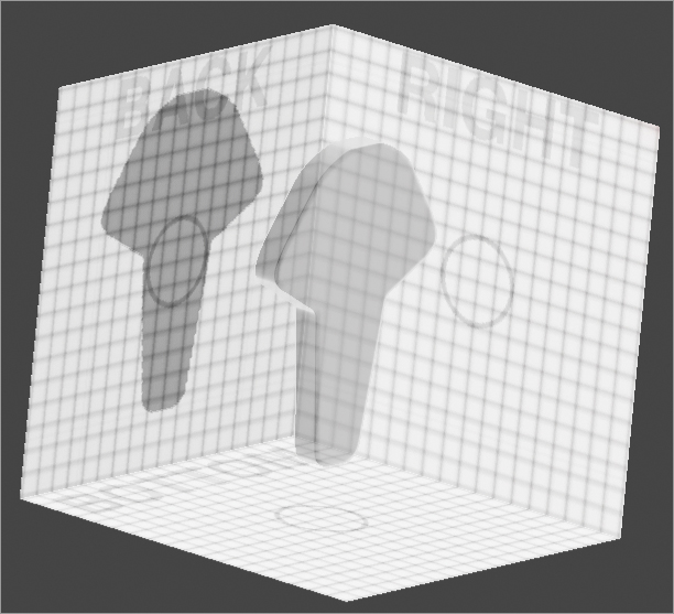
Figure 2-22: Hold the Ctrl key when turning on the BackTrack options you see here.

Making the Zipper Mask
The MaskCurve brush is a great tool for creating lines with harsh or soft angles in the mask because of its ability to draw smooth curves as well as sharp curves. Follow these steps to make the zipper mask:
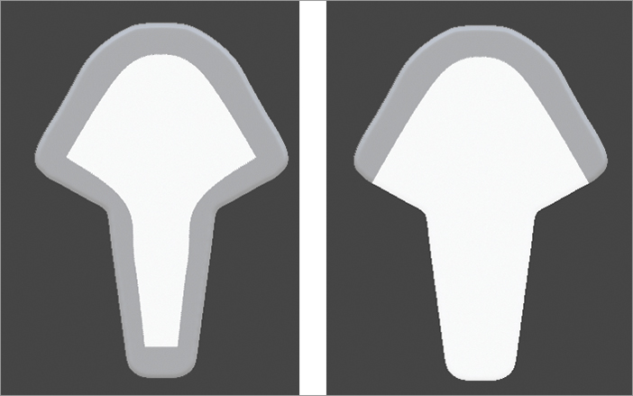
1. Divide the mesh to about 700,000 polygons. Use the MaskCurve brush to mask out the center of the zipper, as shown on the left in Figure 2-23.
2. Create the mask. Click X to enable X-symmetry. With the MaskCurve brush selected, hold the Ctrl key and mask out the top half first. Tap the Alt key when you get close to the top of the zipper to create a curve in the mask (see the image on the right in Figure 2-23).
Figure 2-23: The final masked-out edges of the zipper to sculpt the middle section (left). The MaskCurve brush creates a precise mask on the zipper (right).
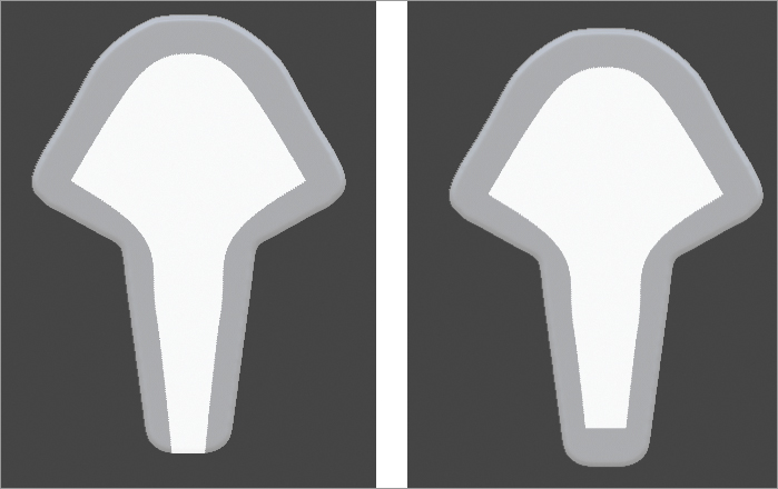
3. Add the first mask by drawing the second mask along the side of the zipper, as shown on the left in Figure 2-24. You can keep adding to any mask in ZBrush by holding the Ctrl key and drawing out a new mask.
4. The last mask is the easiest. Just mask off the bottom of the zipper by drawing a straight line across (see the right image in Figure 2-24).
Figure 2-24: Second mask completed along zipper edge (left), and last mask applied to zipper (right)
5. To create the bevel in the zipper, add a blur to the mask by holding the Ctrl key and clicking the mask. Do this about six times. Each time you click the mask, the edges blur a little more. Hold Shift and rotate the zipper to snap it to a side orthographic view. Then hold Ctrl+Shift and select ClipCurve in the Brush palette. Use the ClipCurve brush to push back the geometry (see the image on the left in Figure 2-25).
6. To create a stronger crease in the form, expand the Deformations subpalette of the Tool palette and move the Inflate slider to the left a few times. This creates a negative inflation of the unmasked area (see the image on the right of Figure 2-25).
Figure 2-25: The result of using the ClipCurve brush (left), and a stronger crease using the Deformation Inflate slider negatively (right)

7. Create the inner bevel by repeating the preceding three-step masking process. Then place the Transpose Line tool in the center of the mesh so you can use the Scale mode to create the bevel. Switch to Move mode to push the geometry back, as shown in Figure 2-26.
Figure 2-26: Tranpose line positioned to create the inner bevel
8. Use the ClipCurve brush to refine the shape of the zipper, as shown in Figure 2-27.
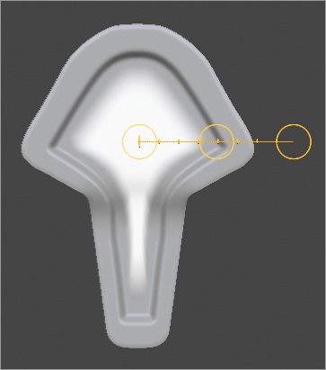
All that is left to do is to create the string of zippers. The duplicate option with the Transpose Line tool when in Move mode will become your best friend for this kind of task.
Figure 2-27: ClipCurve brush used to refine the edges of the zipper

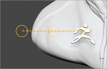
9. Switch to Move mode and draw out an action line just as you see in Figure 2-28. Hold the Ctrl key while you click and move the middle circle to duplicate the zipper. I also like to hold the Shift key here so that the zipper I am duplicating will stay along the line of the Transpose line.
Figure 2-28: Double the zipper subtool

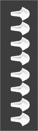
10. To create the rest of the zippers, click the ReplayLast button in the Stroke Palette to continue to move and duplicate the zippers until you get something as shown in Figure 2-29.
Figure 2-29: String of zippers for the hoody
With this workflow, you could create a variety of zipper shapes to add style for your next character model. Don’t forget that each zipper can be polygrouped so that you can move each individual piece of the zipper.
What would a bust be without a stand? To create the stand, I used an old-school tool that is perfect for this job. ZBrush ships with various ZTools, including the primitive meshes. I would like to introduce you to the SweepProfile3D primitive, which is a great way to start a model for the stand for the bust.
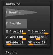
1. Select the SweepProfile3D tool from the library in the Tool palette. Normally you would convert this tool into a polymesh to sculpt it, but this time you’ll use the sliders in the Initialize subpalette to shape the tool before sculpting. These sliders are toward the bottom of the Tool palette when a 3D primitive is selected; you will see a subpalette called Initialize (see Figure 2-30).
Figure 2-30: Initialize subpalette
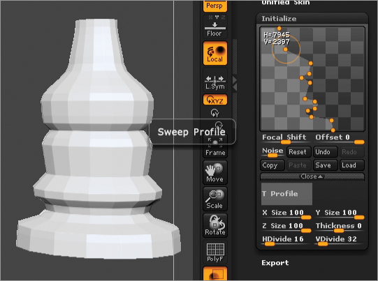
2. Move the points on the S Profile curve so the primitive has a point at the top and is open at the bottom (see Figure 2-31). Don’t worry about the holes at the top and bottom of the mesh. You will take care of that later.
3. Give the point in the middle a sharp edge (see Figure 2-31) by clicking the dot in the graph, dragging it out of the graph and then back into the graph.
Figure 2-31: S Profile edit with a hard point

4. Play around with the S Profile curve to make something like Figure 2-32. This is the start of a stand.
Figure 2-32: S Profile edit to match the model
After you establish the basic shape by using the Initialize settings, it’s time to convert it into a polymesh.
5. To convert your shape into a polymesh, click the Make PolyMesh3D button at the top of the Tool palette.
Now the primitive is a mesh, and the faces are contained within a single polygroup. Polygrouping is key for creating interesting details in the mesh.
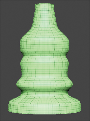
6. Subdivide the mesh and use the result as a test to see where you can crease certain edges. Figure 2-33 shows how the mesh is subdivided and smoothed.
Figure 2-33: The stand mesh has been subdivided.
You don’t want the whole stand to be smoothed; you want some sharper edges, which you can easily make with the Crease feature in ZBrush.
7. Set the SDiv slider in the Geometry subpalette back to 1 and delete higher subdivisions. Then with the SelectRect brush, hold Ctrl+Shift to hide the parts of the mesh. Figure 2-34 shows the middle section of the stand with a sharper edge.
Figure 2-34: Hide parts of the mesh to expose the edges that need to be creased.

8. You can now crease the open edge by clicking the Crease button in the Tool Geometry subpalette, as shown in Figure 2.35. The creased edge appears dotted, as shown in Geometry subpalette, as shown in Figure 2.35. The creased edge appears dotted, as shown in Figure 2-36.
Figure 2-35: The Crease button creases the edges exposed.

Figure 2-36: A creased edge is indicated by a dotted edge.

9. Continue to hide parts of the mesh and crease the edges. Next, use the Edge Loop button to add polygons to certain areas. When you click Edge Loop, ZBrush adds a new row of polygons around the exposed edges. Just as you did for the ZMan logo, hide the geometry you want to add an edge loop to. In Figure 2-37, you can see the sections where I added an edge loop.
Figure 2-37: Parts of the mesh are hidden, and edge loops are added to the visible polygons.
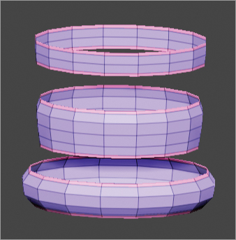
10. Now shrink the polygroups again by clicking Ctrl+Shift+S so you can mask off only the purple polygroup. (Your polygroup may be a different color because ZBrush assigns polygroup colors randomly.) After masking off the purple polygroup, unhide the whole mesh back so you can invert the mask to achieve what you see in Figure 2-38.
Figure 2-38: Purple polygroups masked off (your model may use a different color).

11. Now add a little volume: expand the Deformations subpalette of the Tool palette and push the slider to the right a little. The result is shown in Figure 2-39.
Figure 2-39: Inflating the unmasked areas of the stand

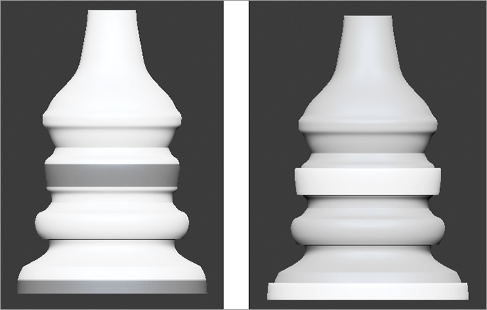
12. Clear the mask by Ctrl-dragging on any open part of the canvas. Now when you subdivide the mesh four times, you get results similar to Figure 2-40.
Figure 2-40: The subdivided stand after the inflation

Figure 2-41 shows this process.
Figure 2-41: The mesh masked out (left), and the result of using the Subtool Extract (right)
Completing the Stand
Finally, you will close up the holes on the top and bottom of the stand so it looks like a solid object:
1. While the stand is at the highest subdivision level delete all the lowest subdivisions by clicking the Del Lower button in the Tool Geometry subpalette.
2. Click the Close Holes button, shown in Figure 2-42, in the Tool Geometry subpalette. This button is available only if the mesh does not have higher levels of subdivision.
Figure 2-42: The Close Holes button in the Geometry subpalette

After you do this, all holes of the selected subtool will be closed. However, if you turn on PolyFrame, you will see that the hole is closed by some large triangles (see Figure 2-43). Even though ZBrush can sculpt on triangles, these triangles are very large in scale and have no uniform geometry flow to them. These triangles are not good for sculpting in ZBrush, especially if you want to subdivide this up to higher polygon counts.
Figure 2-43: The Close Holes button creates triangular polygons that fill the open holes in the mesh.

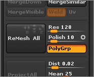
3. Because of the simplicity of this mesh, fixing the large irregular triangles is easy. Activate the eye for only the stand in the SubTool subpalette, as shown in Figure 2-44. For the next step, the stand must be the only subtool used, so we must turn off the eyes for the other subtools. Next click the X in the ReMesh All button off (see Figure 2-45) so that ZBrush does not use the X-symmetry when you remesh the stand.
Figure 2-44: The eye that is on in the SubTool palette will be remeshed.

Figure 2-45: The ReMesh All button with X-symmetry off
4. Click the ReMesh All button. ZBrush creates a new Subtool by skinning a new mesh from the original stand subtool, as shown in Figure 2-46. ReMesh All creates a new subtool of quad polygons with no irregular triangles.
Figure 2-46: New SubTool created from ReMesh All

5. You need to transfer the detail of the original stand to the remeshed version. First select the new remeshed subtool in the SubTool subpalette.
Think of the remeshed version as the target mesh, and the original stand with the triangles subtool as the source mesh. Make sure the eye is on for the original stand. To transfer the detail, use the Project All button in the Tool SubTool subpalette. When you use Project All, ZBrush projects the detail from all visible subtools onto the selected subtool. The correct arrangement is shown in Figure 2-47.
Figure 2-47: The bottom subtool is the remeshed version of the original triangle mesh.

6. Click the magic Project All button in the Tool SubTool subpalette (see Figure 2-48).
7. When using Project All to transfer detail from one subtool to another, you may get the best results by projecting detail on each subdivision level. Start from the lowest Sdiv on the target mesh (remesh stand) when the source mesh is set to the highest-level (original triangle stand) setting and Project All at each subdivision level, working up to the highest level. As shown in Figure 2-49, Project All is used on level 1 of the target mesh in the left image, and then subdivided up to Project All again in the middle image, and the same process is used in the third image.
Figure 2-48: Project All button in the Subtool subpalette

Figure 2-49: The Project All completed on three levels

In Figure 2-50, the stand is now a completely quad mesh with the same detail of the original stand. This is a desirable mesh for sculpting because of the evenly disrupted polygons.
Figure 2-50: Finished remeshed stand with details projected from the original stand mesh
Project All is a powerful tool to create a new base mesh when you need to get your sculpted detail back from the original sculpture.
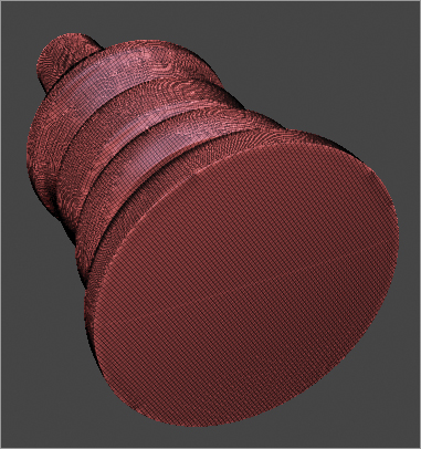
The approach that I describe here for creating skin detail is extremely simple. This technique is about building up the skin in layers. For the sake of understanding the various ways to use this technique, I will demonstrate it on a sphere:
1. Load a polysphere from LightBox, draw it on the canvas, and activate Edit mode (hot key = T). Subdivide the polysphere to level 6, which will give you 1.572 million polygons.
2. Start the base of skin by using the Surface feature, which is a subpalette of the Tool palette. Activate the Noise button. Figure 2-51 shows what happens to the surface of the mesh.
3. Adjust the Scale and Strength sliders as well as the Noise curve to produce the result shown in Figure 2-51. Just get your setting close to those below:
- Noise Scale = 4
- Strength = -0.014
- Focal Shift = 86
Figure 2-51: Surface Noise settings

4. Move the SNormal slider at the bottom of the palette all the way to 100. This limits the amount of inflation that can occur when you apply the noise to the mesh.
5. Apply the Surface Noise by clicking the Apply To Mesh button to give you what I have in Figure 2-52. You can also apply a slight smooth to this in the Tool Deformation subpalette.
Figure 2-52: Surface Noise results

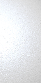
When I turn up the specularity on the SkinShade4 material you can see this first pass will help to break up the specularity on a model (see Figure 2-53). Therefore, the light that passes over a face will be less harsh in areas of high light concentration. A specular area is an area where more light concentrates and that has a shiny look.
Figure 2-53: Surface Noise will break up the specular reflections of the mesh, increasing the realism of the skin texture.
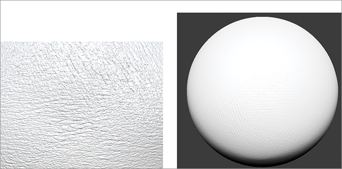
The next step is to create creases in the skin texture. The Skin brush is the perfect tool for creating this type of detail.
6. Go to the LightBox Brush Patterns folder. Double-click the Skin1 brush to select it. Alternate the brush size and move closer to the polysphere to see what the Skin brush does when applied (see Figure 2-54).
Figure 2-54: Skin brush applied up close to the polysphere (left), and the skin brush applied to the polysphere further away from the camera (right)
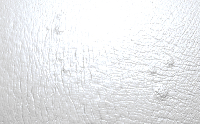
7. Finally, apply the kind of organic imperfections you usually see on skin. Select the Standard brush and set the Stroke type to DragRect. Select Alpha 04 from the Alpha library (see Figure 2-55). Use the brush to add blemishes, as shown in Figure 2-56. You can always save these brushes to use on any model by clicking Save As in the Brush palette.
Figure 2-55: The results of the Standard imperfection brush
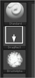
Figure 2-56: A customized version of the Standard brush used for imperfections

8. Use the Clay brush with DragRect stroke and Alpha 04 applied. Set the Z Intensity slider to 32.
Continue to apply different alphas to these brushes to add more imperfections, as shown in Figure 2-57.
Figure 2-57: More imperfections added
Let’s see how we can add alphas from LightBox to any brush.
9. On the DVD, you will find the file SW_Pores_05.psd in the Chapter 2 Assets folder. Load this file into the following directory of ZBrush so that you can load it from LightBox:
Windows = C:/ProgramFiles(x86)/Pixologic/ZBrush4r2b/ZAlphas
Mac = Applications/ZBrushOSX4r2b/ZAlphas
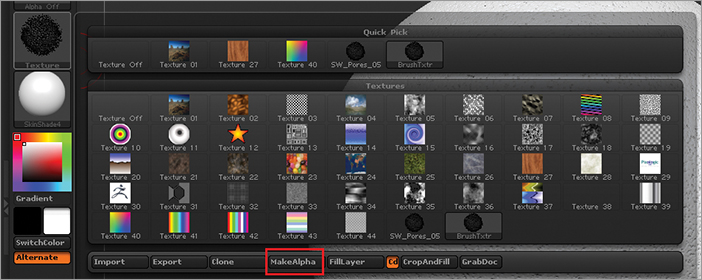
10. Back in ZBrush, open the LightBox Alpha menu. You will see a texture called SW_Pores_05.psd. Double-click this alpha twice. The alpha is loaded as a texture to the select brush, which should be the Standard brush, as shown in Figure 2-58.
Figure 2-58: SW_Pores_05.psd added to the selected brush

11. To apply this texture to the Alpha palette, click the MakeAlpha button at the bottom of the fly-out window (see Figure 2-59). This button converts the selected texture into a grayscale image and places it in the Alpha library. You can then apply the alpha to your Sculpting brush.
12. Now that you have created an alpha from the texture SW_Pores_05.psd, select the alpha on the Clay brush so you can use it on the mesh to create skin pores as I did.
You can see how amazing the result is when you use a custom detailing brush on your mesh. Continue to experiment with these techniques.
Figure 2-59: The MakeAlpha button at the bottom of the Texture fly-out window
The brush system in ZBrush is pretty incredible. The next chapter will take you through some really great tips for sculpting in ZBrush.
Artist Spotlight: Morgan Morey
Using QuickSketch to Hash Out Jewelry Ideas
I’ve been using ZBrush for a long time to design jewelry, and I only recently realized how useful a tool QuickSketch is. QuickSketch is found at the top left of the interface. When you couple the initial tool with the Lazy brush, it can be powerful.
After you click the QuickSketch button, ZBrush will switch to a PenShadow brush and fill the document with a 3D plane. Turn on LazyMouse in the Stroke palette, as shown in Figure 2-60.
Figure 2-60: Turn on LazyMouse in the Stroke palette.

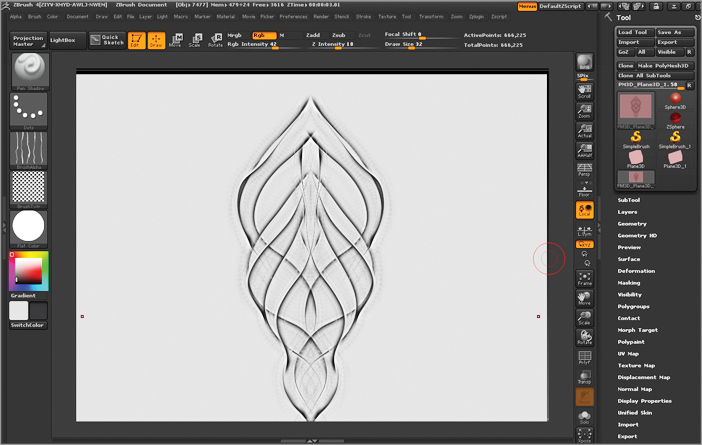
With X symmetry on with these settings, you can draw superb curves and the most elegant shapes in a few strokes of a brush, as you can see in Figure 2-61.
Figure 2-61: With x-symmetry on you can get smooth lines.
After you establish your line work, you can then add color to create loose paint-ups; just turn off the texture of the brush and set the alpha to 28 or any other of your preference. Make a few more strokes, and you have a great reference to begin your sculpt, as shown in Figure 2-62.
Figure 2-62: Finished reference image to sculpt from

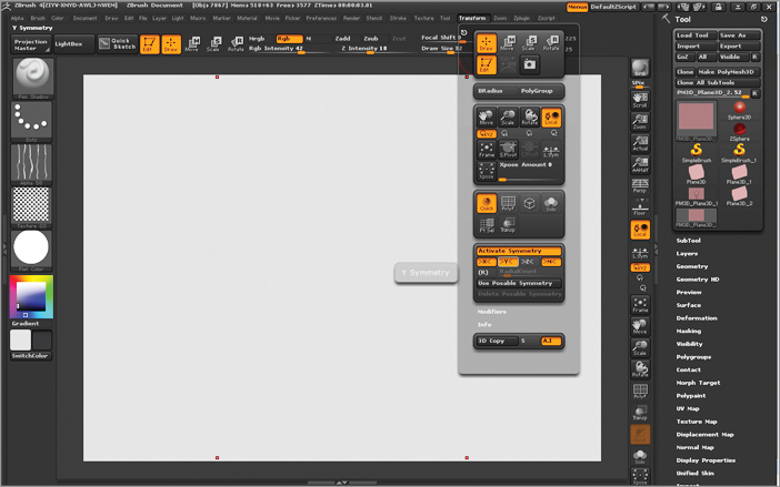
When designing a ring, QuickSketch enables you to use symmetry to your advantage. Choose Transform Active Symmetry Y and you will have two axes of symmetry for your brush (see Figure 2-63).
Figure 2-63: Along with x-symmetry turn on y-symmetry in the Transform palette.
With both X and Y symmetry on, you can draw a four-way symmetric ring with ease. I generally start by drawing the stone shape I’ll be working around and the setting, and then I draw the shoulders and shank as I see fit. Next I turn off the Y symmetry and draw the side view of the ring so I can see how each element interacts, as shown in Figure 2-64.
Figure 2-64: Draw out the side of the ring.

If I’m working on a very complex design, I create a cross viewport with two images so I can design in 3D space. This way, I can see both 2D designs. I do this by duplicating the plane and using the Transpose tools to rotate and position as necessary, just as in Figure 2-65.
Figure 2-65: Duplicate the plane and rotate it.
Using ShadowBox with My QuickSketch Design
ShadowBox is one of the greatest tools Pixologic has come up with in recent years. It allows you to draw geometry in simple brush strokes by using the Masking brush to define the form from two or three planes.
With this in mind, you can combine masking brushes with symmetry and Lazy Mouse to generate fantastic intricate lattices and easily define natural form.
This next part is optional but still useful. If you have an image you want to use as a reference, follow these steps to assign your 2D design to a 3D plane:
1. Create a 3D plane in the Tool palette.
2. Make the 3D plane a polymesh by clicking the Make PolyMesh3D button at the top of the Tool palette.
3. Import the image you want into the Texture palette.
4. In the Tool Texture Map subpalette, select your imported texture so it is assigned to the plane.
5. Adjust the plane by using Transpose Line as necessary and using Move mode to stretch it.
Figure 2-66 is my QuickSketch design assigned to a plane by using the preceding steps.
Figure 2-66: QuickSketch design assigned to the plane

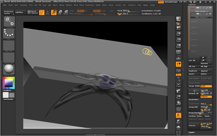
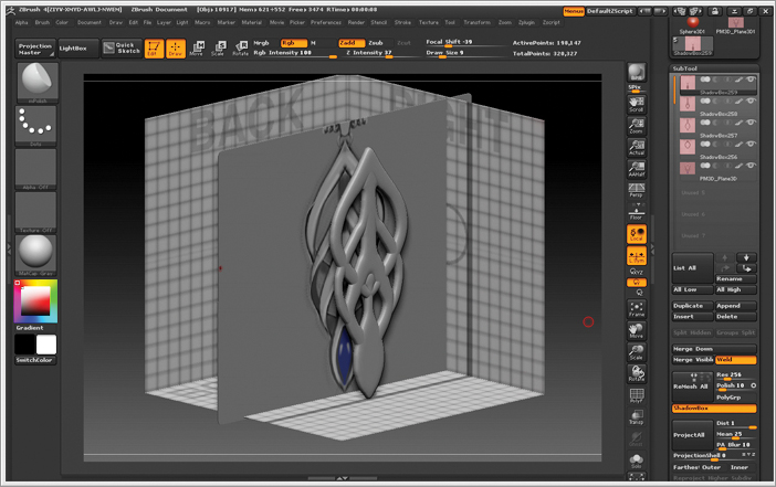
6. Open LightBox. Under the Tool menu, slide across to ShadowBox256.ZTL. Double-click this tool to load it into the Tool palette. Then append your image plane to the ShadowBox. Use Transparency without Ghost on to line up your design to the ShadowBox, just as I did in Figure 2-67. Remember that Transparency and Ghost are on the right side of your interface.
Figure 2-67: Make sure Ghost is off when Transparency is on.
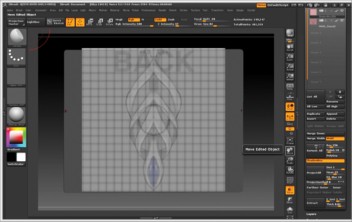
7. If you hold Ctrl and mask out the back panel based on the design, you will see the geometry created immediately, as shown in Figure 2-68.
Figure 2-68: Based on the design, mask out the back face of ShadowBox.

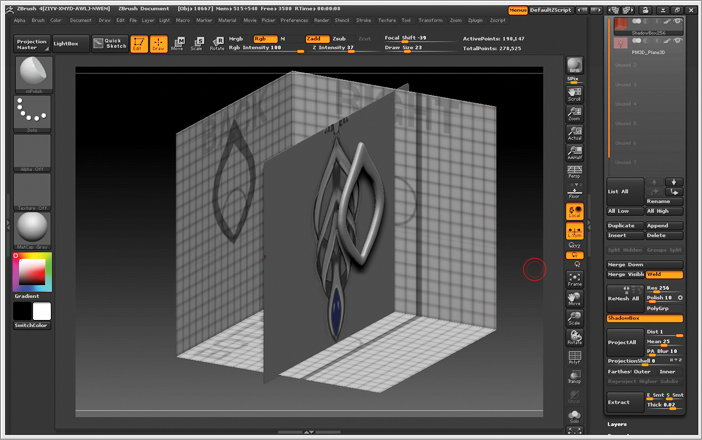
8. If you want to change the thickness of the mask, the other two panels need to be introduced: Ctrl-click and drag a box with MaskRect over the other two panels. You can draw a design on the other two axes. However, I find it easier to draw the parts flat and change their shape with conventional methods by using Move mode. Figure 2-69 shows the masking of the other two panels to adjust the thickness.
Figure 2-69: Masked out all three panels of ShadowBox
9. It is important to note that you can put too much detail into masks when using ShadowBox. I tend to draw one element per ShadowBox, so duplicate the element in the SubTool subpalette by clicking the Duplicate button and then erase the mask on the back plane without erasing the other two planes. If you do it right, you will use just the mask on the side and bottom planes, and you’ll have a giant square in the way of your panel. So generally I leave a little of the previous design behind, which I erase later to give me the result you see in Figure 2-70.
Figure 2-70: Results from the mask
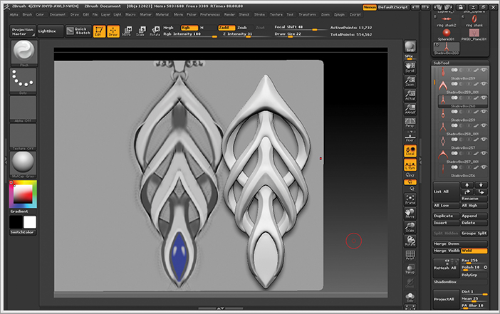
You can repeat this process of duplicating and redrawing the mask as many times as you want; the advantage of starting a new ShadowBox is that the thicknesses will be uniform. When you are happy with your design, go back down the SubTool stack and turn off the ShadowBox button. Enjoy your finished work. My finished piece appears in Figure 2-71.
Figure 2-71: Finished piece from ShadowBox

The best way to layer and interlace your pieces is to use the Move brush while holding the Alt key. This will push or pull the mesh along the normals. After you use the Move brush a little, you should get something similar to Figures 2-72 and 2-73 below.
Figure 2-72: Finished piece with adjustments using the Move brush

Figure 2-73: Another view of the finished piece
Exporting for Printing
So you’ve finished a fantastic piece of jewelry that will be the envy of all your friends, but you need to bring it into reality.
You need to ask yourself some questions to determine whether your design is feasible:
- Are there floating parts?
- Is everything well intersected?
- Are there holes in the geometry?
You learn these things with practice, so I can’t give you all the questions and solutions. But I will do my best. After your piece passes this initial inspection, you can move forward:
1. Save your piece separately and save it somewhere safe. I cannot stress this enough, because if the file corrupts or something else happens, you will be devastated, especially if you plan to use your design in your business. So be sure to back up your project.
2. Merge your visible subtools and select the tool you created. Now the model needs to be decimated, because when you send it to your printers, you must send a file that is about 15–20 MB, depending on your printer preferences. Open ZPlugin Decimation Master, as shown in Figure 2.74. If you haven’t installed Decimation Master, you can find it on the Pixologic website: www.pixologic.com/zbrush/downloadcenter/zplugins/.
Figure 2-74: Use the Decimation Master plug-in to reduce the polygons.
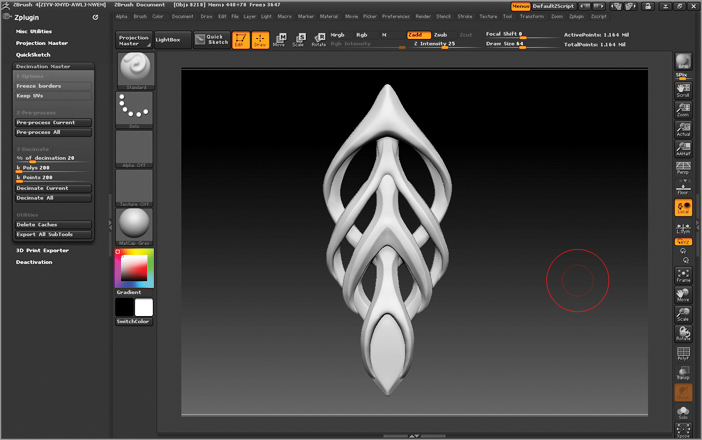
3. In Decimation Master, select Pre-Process Current. Now go make a cup of tea, because depending on the power of your computer and the total poly count of your model, the processing can take a while. You’ll know when the job is finished, because you can rotate the model again.
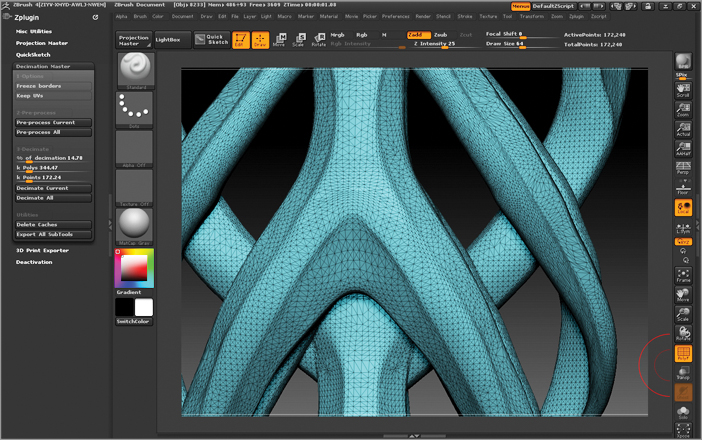
In Figure 2-75, you can see that the mesh is high in poly count and is completely quaded.
Figure 2-75: The mesh is high in poly count and all quads.

4. Next move the % Of Decimation slider until the K poly is around the 330–380 mark to make the file size something reasonable for the printers. You can also move the K poly slider to your desired poly count. Then select Decimate Current. After you do this, you won’t really see any difference, but the poly count of the model will have changed, as you can see in Figure 2-76.
Figure 2-76: The mesh with less polygons and all triangles.
5. Save your file with DECIMATED appended to the end of the filename. Save the tool. I also like to save an OBJ version by clicking Export in the Tool palette so I can render it later.
6. Open the plug-in 3D Print Exporter in the ZPlugin palette. Once again, if you do not have this installed, you can get it from the Pixologic website at www.pixologic.com/zbrush/downloadcenter/zplugins/.
7. In the 3D Print Exporter, select Update Size Ratios. I generally like to work in millimeters (mm). Choose your sizes and click STL Binary. Most printers I use prefer STL Binary, but if your printer uses one of the other file extensions, use those. Save your file, and that’s your model ready to print. If you are not sure about sizes, get a ruler and measure the model onscreen to see what it will look like.
You will know that your file has been saved as an STL file when you see the following dialog box (Figure 2-77).
Figure 2-77: Menu indicating that the file was successfully saved as an STL.

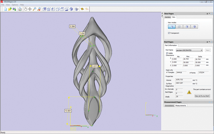
I generally like to check my STLs before I send them off, so I can find volumes, check thicknesses, and see whether there are any problems in the mesh. For this, I use MiniMagics 2.0, which is a free program. Here is a quick rundown of checks you should make:
- Check the volume in MM3. From this, you can work out weights in metal.
- Run diagnostics.
- Inversed normals and bad edges usually occur when geometry is collapsed. This is generally bad but can be fixed by the printers.
- Mesh Shells – When there are separate SubTools the printers will fix this with a push of the button.
- You can also measure areas to check thicknesses if needed.
In Figure 2-78, you can see how I used MiniMagics to measure the piece.
Figure 2-78: The mesh with less polygons and all triangles.
Morgan Morey grew up in a family of artists, so he initially studied 3D animation as a way of doing something artistic while at the same time something different from his parents’ jewelry work. However, after graduating and spending a year sitting around emailing places for work, to no avail, he took up the craft of jewelry making after being inspired by a visit to the International Jewellery London trade show. Sounds like something from Star Wars: “It is inevitable” that you will follow in your parents’ footsteps.
But how often in life do you get the chance to do something very few people are doing or have even considered? So now he creates jewelry by using ZBrush to design levels of detail impossible to achieve by hand. He is currently working on building up a business from scratch to sell ZBrush jewelry on commission and for retail. He also advises on ZBrush CAD workflow.
Creating Mesh Thickness without Losing Subdivision Levels
One of ZBrush’s main workflow advantages is having the ability to step down to lower levels of subdivision to make quick global changes. In this section, I’ll showcase a technique that lets you add details to a single-sided mesh at a high subdivision level, give the mesh a thickness, and then reconstruct your lower subdivision levels.
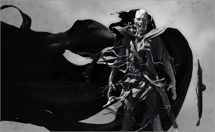
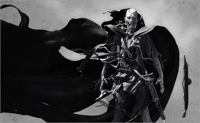
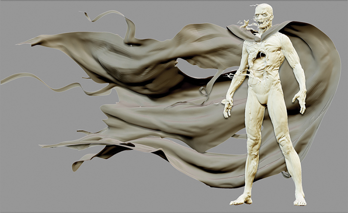
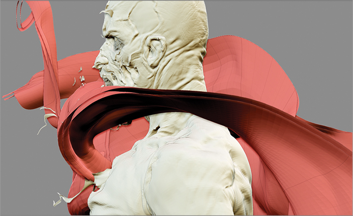
This technique was used to add thickness to the cape and clothing items as well as the numerous bits of floating flesh on this Bogman character from Adaboy, The Sculpted Novel (see Figure 2.79).
Figure 2-79: Final cape on Bogman
Let’s look at the creation of his torn cape:
1. Create a low-poly base mesh in ZBrush or any external modeling package. In ZBrush, you can start with a flat plane by using Plane3D in the Tool palette. Click the Make PolyMesh3D button in the Tool palette to convert the geometry into a polymesh, and then choose the Tool Reconstruct Subdiv button to achieve your desired mesh density.
2. Click the Tool Geometry Crease Edges button before you begin sculpting to help prevent the cape from shrinking when you create higher subdivision levels (see Figure 2-80).
Figure 2-80: Add creasing to the cape to prevent shrinking.

3. Begin to refine your form. At this stage, avoid all high-level detail and focus on the global low-subdivision-level masses.
4. Evaluate the overall shape, form, and gesture of the cape. Use the Move brush, Standard brush, and Transpose Mode to achieve the desired results.
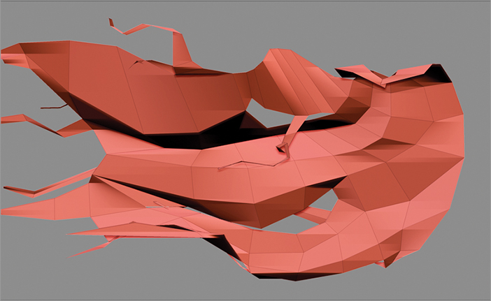
In Figure 2-81, I blocked in the overall scale and gesture of the cape. Throughout this process, I turned on the visibility of the character and other costume subtools to evaluate their overall relationships.
Figure 2-81: Using the Move brush to block out the overall shape of the cape
5. Create higher levels of subdivision by using Tool Divide and then continue to refine the form.
6. Use the Move brush and Inflate brush on the main sections of the cape, and the Transpose mask to quickly rotate, scale, and reposition the long strands of tattered cloth.
7. Continue to refine the mesh. Remember to step down to lower levels to make global changes. As a general rule, you will want to step down to the lowest level possible to achieve the desired changes.
8. Refine the sculpt to a level that shows your design intention, but don’t add any finite surface detailing (see Figure 2-82). We’ll save that for our final step.
Figure 2-82: Refine the cape with more subdivision levels.
9. Now let’s add thickness. Press Shift+S or click the little camera icon in the Transform palette to take a screen capture of your mesh. This will allow you to see the amount of thickness we are about to create for our cape.
10. Without moving your mesh, store a morph target by choosing Tool Morph Target StoreMT.
11. After you save a morph target in the Tool Deformation subpalette, use Inflate to offset your mesh. The amount of offset in the base-cape screen capture and the inflated cape will determine our new thickness.
Figure 2-83 showcases the cape thickness we are about to create. It’s important to note that we still have only a single-sided mesh. The screen capture we did in step 9 is only a visual cue.
Figure 2-83: With a screen capture, adjust the cape to the desired thickness.
12. To create a mesh with thickness, choose Tool Morph Target CreateDiff Mesh. Remember, if you have not stored a morph target, you will not be able to create a difference mesh.
13. The mesh is created as a new tool in your Tool palette. Select the new tool to view your cape with thickness! If you turn on the wireframe, you’ll notice that ZBrush automatically created three polygroups: one for the outside surface, one for the inside surface, and one for the edge thickness. If you do not see all three sides of the mesh, just click Double in Tool Display Properties (see Figure 2-84).
Figure 2-84: Turn Double on in Tool Display Properties to see all three sides.

14. Using Tool Append, select the new cape mesh and append it as a new subtool. This will add it to our list of subtools for our character.
With a clean, well-defined form, our sculpt could be complete, but let’s take things one step further. Next we will use a trick that lets us reconstruct subdivision levels. In order to reconstruct subdivisions on the new mesh, we’ll need to add a few edge loops to the edge thickness polygroup.
15. Shift+Ctrl-click on the edge thickness polygroup to isolate this section of the cape. You should now see only the polygroup representing the edge thickness.
16. Next we will insert edge loops. With the correct number of edge loops inserted in this polygroup, ZBrush will let us reconstruct lower levels of subdivision on the entire mesh. First let’s figure out how many edge loops we need to add. Go back to your original cape mesh, step down to the lowest level, and hide everything except one polyface. Step back up to your highest level. Count the number of spans added, and you’ll know exactly how many spans we need to add to our new edge thickness polygroup. Figure 2-85 shows how many spans I have at the highest subdivision level of the original single-face cape. We need to add 15 edge loops.
Figure 2-85: Count the spans to figure out the number of edge loops needed.

17. Go back to the new cape subtool and isolate a selection on the edge thickness polygroup by holding Shift+Ctrl while clicking on a polygroup that represents the thickness. With the edge thickness polygroup visibility isolated, use Tool Edge Loop to insert 15 new edge loops.
Figure 2-86 shows the edge loops we are adding to the new polygroup on the new cape. So far, we’ve added four.
Figure 2-86: Four edges loops have been added.

18. After adding 15 new edge loops, use Tool Reconstruct Subdiv to re-create the lower levels of the subdivisions in the mesh.
Figure 2-87 shows the final result of my cape on the lowest subdivision level and the highest subdivision level.
Figure 2-87: Final result on the highest and lowest subdivision levels

You should now be able to step up and down through all the levels of division on our new mesh with thickness. This is a great technique to use on everything from belts, boots, and pants, to bits of floating flesh. Good luck!
With a commitiment to driving the digital entertainment industry forward, Zack Petroc continues to develop new techniques that redefine how digital tools impact the art and design of storytelling. In 2005, he opened Zack Petroc Studios to focus on the development of unique new content and provide like-minded artists an avenue for creating an independent property (IP). The Studio’s first IP, TheAdaboy.com, gives viewers direct access to behind-the-scenes story development techniques, allowing them to follow along as it evolves from concept to completed project. Additionally, his studio has worked on the development of several feature films and video games, with a recent client list that includes Disney Interactive Studios, Scott Free Productions, SCEA, Walt Disney Imagineering, Snoot Entertainment, Hasbro, and Paramount Pictures.
Zack also has a passion for teaching and training digital artists. In addition to lecturing at universities across the US and abroad, Zack has headed several workshops and training seminars at leading industry companies. Recently he created one of a kind training tools and advanced Master Classes available via www.zackpetroc.com.
Check the included DVD for details on a special Zack Petroc Studios Premium Member discount. Currently he enjoys spending his days as Model Supervisor and Studio Department Lead at Disney Feature Animation, interacting with some of the most talented artists in the industry.