
Chapter 7
Posing—Bringing Movement to Your Work
After you create a cool character, you need to bring that creation to life. This chapter covers how to create dynamic character poses for rendering out an image. This is often a part of sculpting that people have trouble accomplishing or put off for as long as possible. But if you have a great sculpt, there is nothing cooler than putting that sculpt in a really dramatic pose.
Two major features in ZBrush allow you to pose a character. I find that using a ZSphere rig works well for moving the limbs to establish the overall pose. Then I like to use the Transpose line to add subtle changes that finish the pose.
- Setting up a ZSphere rig with a single subtool
- Rigging a single subtool with sculpted detail
- Using a rig with Transpose Master
- Creating multiple poses with layers
- Assigning multiple poses to the timeline
- Exporting blend shapes from ZBrush to Maya
Setting Up a ZSphere Rig with a Single Subtool
In this first section, you will start with the simple task of building a rig for a full human character that has no subtools. Now, I’m not going to leave you hanging, with just the following words and images to teach you how to build a rig; make sure to watch the video for this section. The video, Rig_Step1.mov, is in the Videos folder of Chapter 7. Then follow these steps:
1. Load a project that is already installed in ZBrush. Open LightBox, and under the Project menu, double-click the DemoProjects icon. Click the project called SuperAverageMan.ZPR, as shown in Figure 7-1, and then double-click this project to load it into ZBrush.
Figure 7-1: Load the SuperAverageMan.ZPR project into ZBrush.

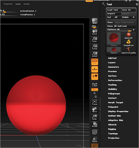
2. Now you need to build the rig. In the Tool palette, select the ZSphere. This automatically swaps the SuperAverageMan for a ZSphere in the ZBrush document (see Figure 7-2).
Figure 7-2: Select the ZSphere in the Tool palette.
3. While the ZSphere is on the canvas, open the Rigging subpalette of the Tool palette, and click the Select Mesh button. As you can see in Figure 7-3, the tool selection fly-out window opens. Click SuperAverageMan.
Figure 7-3: Click the Select Mesh button in the Rigging subpalette to select SuperAverageMan.

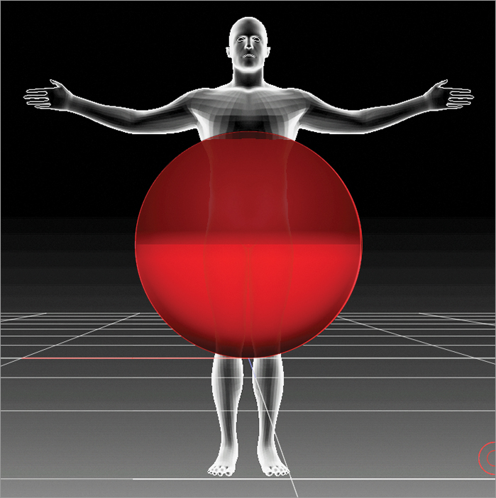
This places the SuperAverageMan into the document with the ZSphere. Figure 7-4 shows that the SuperAverageMan is also in Ghost Transparency mode.
Figure 7-4: SuperAverageMan added to the ZSphere with Ghost Transparency turned on
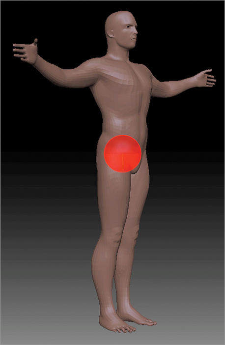
4. You don’t want Ghost Transparency on because you will not be able to snap ZSpheres to the mesh in the next step. So turn it off by first turning on the Transparency button on the right of the interface. The Ghost button right below it also turns on. Turn the Ghost button off so that your SuperAverageMan is no longer in Ghost Transparency mode (see Figure 7-5).
Figure 7-5: Turn off Ghost to see the SuperAverageMan clearly.

5. Click the X key to activate x-Symmetry mode. If you are not sure symmetry is on, go to the Transform palette and make sure the Activate Symmetry button is on along with the X button.
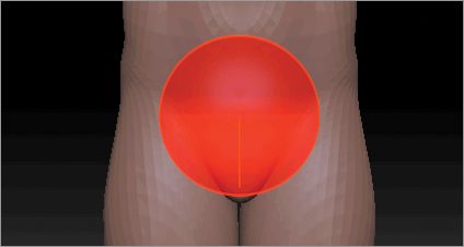
6. Switch to Scale mode at the top of the interface to scale down your ZSphere to fit into the SuperAverageMan—the ZSphere will act as a pelvic bone (see Figure 7-6). Use Move mode to place the ZSphere into the position of a pelvic bone.
Figure 7-6: Use the Scale and Move modes to position the ZSphere to act as a pelvic bone.
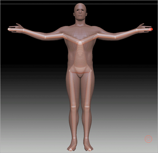
7. Now you are ready to start drawing out a rig. The ZSphere should still be selected; if not, switch to Move mode and click the ZSphere to select it. (See Figure 7-7 for a selected ZSphere, which is indicated by a middle red circle.)
Figure 7-7: Make sure to select the ZSphere by using Move mode.
8. Switch to Draw mode and click on either side of the ZSphere to start the leg bone (see Figure 7-8).
Figure 7-8: Click on the mesh on either side of the ZSphere to begin drawing out the leg bone.
9. Now, making sure that the last drawn-out ZSphere is selected, continue to draw by clicking on the mesh, down the leg. Add a ZSphere at the knee, then at the ankle, and then at the heel, and finish off at the toes (see Figure 7-9).
Figure 7-9: Continue to draw out ZSpheres down the leg.
To make it easy on yourself when selecting which ZSphere to draw from, I recommend switching to Move mode to select a ZSphere. Then switch back to Draw mode to draw out where the next ZSphere needs to be.
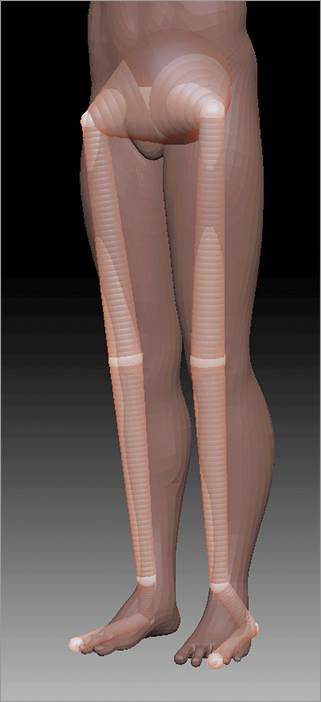
10. Turn your SuperAverageMan to the side. You may notice that the ZSpheres you have just drawn out are not sitting inside the model. This is an easy fix. Just switch to Move mode again and position the ZSpheres so your model matches Figure 7-10.
Figure 7-10: Use Move mode to position the ZSpheres into place. The left image shows the original ZSpheres’ positions, and the right shows where I moved them.

11. Let’s continue up the body. In Move mode, select the pelvic bone ZSphere again (switch modes with the shortcuts W = Move and Q = Draw).
Now in Draw mode, draw out the upper body (see Figure 7-11).
Figure 7-11: Draw out the upper rig.
12. As with the lower legs, you need to switch to Move mode to position the ZSpheres into the correct spot (see Figure 7-12).
Figure 7-12: Switch to Move mode to position the ZSpheres.

13. Switch back to Move mode to select the ZSphere at the chest. Switch to Draw mode and finish off the top of the body (see Figure 7-13). You can also see that I have already positioned the final ZSpheres.
Figure 7-13: Finish the upper torso.

14. Add two sets of rib joints (see Figure 7-14). Click anywhere between the pelvic bone ZSphere and chest ZSphere to add another ZSphere between them.
Figure 7-14: Add two sets of ribs to the rig.

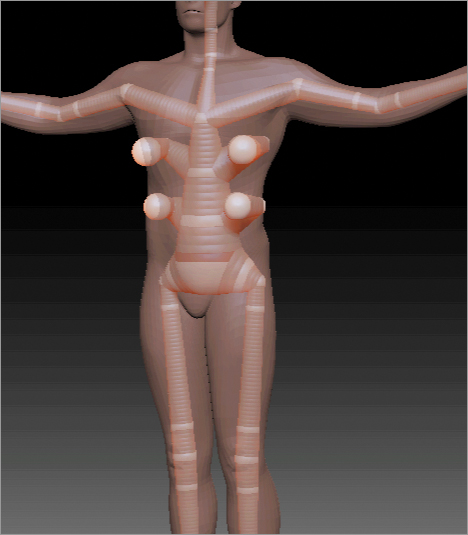
15. Place ZSpheres on either side of the elbow, hip, and knee joints (see Figure 7-15). This will give a better bend at the joints.
Figure 7-15: Add ZSpheres on either side of joints to create a better bend when posing.
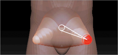
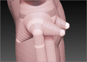
16. Finally, add a ZSphere at the front crotch and two at the buttocks of the character so you can have individual movement there (see Figure 7-16).
Figure 7-16: Add one ZSphere at the front and two at the back for precise movement.
17. In the Tool Rigging subpalette, turn on the Bind Mesh button.
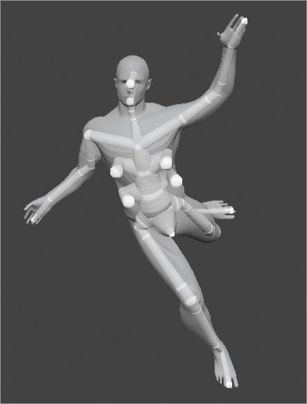
You are now free to pose away. Switch to Rotate mode and click any ZSphere chain that is between any ZSpheres to pose your character. Don’t forget to click the ZSphere itself instead of the chain to make a more central rotation. Switch to Move mode to use built-in IK (Inverse Kinematics) with a ZSphere. Then turn off Symmetry so you can make some crazy poses (see Figure 7-17).
Figure 7-17: With a rig completed, you can pose the character in any way.
Adaptive Skin subpalette or use the shortcut A. To make a tool, click the Make Adaptive Skin button, and ZBrush will create this preview as an actual mesh.
Rigging a Single Subtool with Sculpted Detail
Now let’s look at how you handle a mesh with details sculpted into the surface. I would like to thank Caroline Delen for allowing me to use her sculpt in this section.
Figure 7-18 shows the sculpted detail and five subdivision levels on the model. You can view a video of the whole process in the Chapter 7 Videos folder. The video is called SingleSubToolwithDetail.mov.
Figure 7-18: Single subtool with five levels of sculpted subdivisions

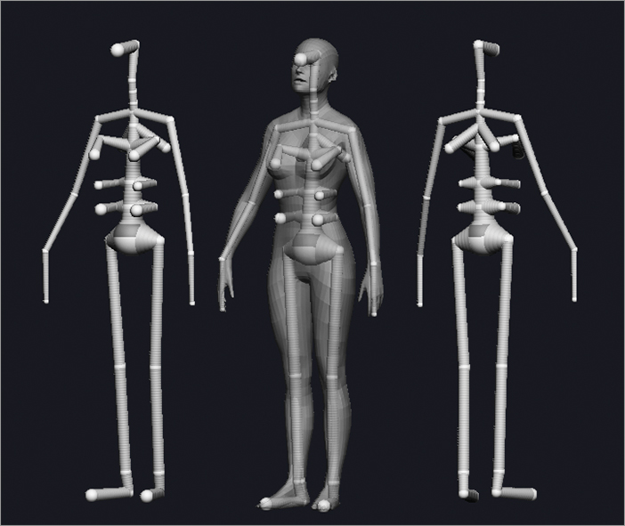
1. Load the Julie.ZTL tool from the Chapter 7 Assets folder. Drop the sculpted step to the lowest level and create a rig, as you did in the preceding section. Figure 7-19 shows the rig I built for the model. Notice the extra ZSpheres added to her back and chest.
Figure 7-19: Rig of the woman
2. Before you begin posing, you need to complete some key steps so the sculpted detail is transferred to the pose. First turn Bind Mesh on in the Tool Rigging subpalette.
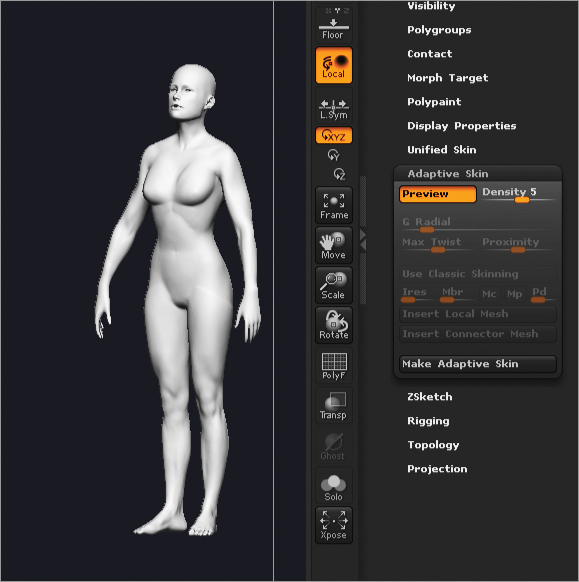
3. In the Tool Adaptive Skin subpalette, set the Density slider to match the same subdivision level of the mesh. Here it is set to 5 because the model has five subdivision levels.
4. Hold Shift and click the Preview button in the Tool Rigging subpalette. This puts your mesh into a Preview mode with the sculpted detail coming in (see Figure 7-20).
Figure 7-20: Shift-click the Preview button.
5. While in Preview mode, you must click on the mesh at least once. ZBrush needs an interaction with the model to verify the sculpted detail on the highest subdivision level so that the detail will transfer when posed.
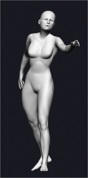
6. Now you are free to pose the tool. Let’s take the model out of Preview mode and pose her. Figure 7-21 shows the pose and all the sculpted detail that has been transferred.
Figure 7-21: Posed character with sculpted detail transferred
Using a Rig with Transpose Master
Now let’s look at how to pose a character when you have several subtools with several subdivision levels. Another video in the Chapter 7 Videos folder, Rig_Step2.mov, can help you with this process.
To pose a character with several subtools, you will use the ZBrush plug-in Transpose Master. This is automatically installed with ZBrush 4R2, and you can get updates on the Pixologic website at www.pixologic.com/zbrush/downloadcenter/zplugins/. Follow these steps:
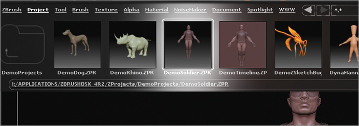
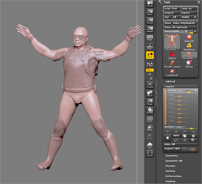
1. Open LightBox again with the Project menu selected and in the DemoProjects folder open the DemoSoldier.ZPR project. Double-click this project to load it into ZBrush (see Figure 7-22).
Figure 7-22: Load the DemoSoldier.ZPR project in the DemoProjects folder of the Project menu.
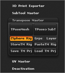
2. From the ZPlugin palette, open the Transpose Master subpalette and click the ZSphere Rig button (see Figure 7-23).
Figure 7-23: Click the ZSphere Rig button.
3. Click the TPoseMesh button. All 11 subtools of the DemoSoldier automatically drop to level 1 and merge as one with a ZSphere at the center (see Figure 7-24). This process also actually creates a new tool.
Figure 7-24: The TPoseMesh button merges all subtools into one with a ZSphere at the middle.

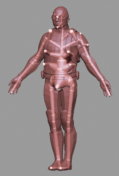
4. Turn off Ghost Transparency. Then build the rig as you did in the prior section, “Setting Up a ZSphere Rig with a Single Subtool” (see Figure 7-25).
Figure 7-25: Completed rig in TPoseMesh
5. I saved this as a project so you can load it into your own ZBrush 4R2 program. However, you must load the project through the SubTool Master plug-in: click the Load TM Prj button. The project, Step2.ZPR, is in the Assets folder of Chapter 7.
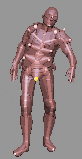
6. Look closely at the extra ZSpheres I added to control things such as the backpack, shoulder straps, shoulder guard, and so on. You can see all of these added ZSpheres in Figure 7-26.
Figure 7-26: Add some ZSpheres for more control on certain subtools.

7. Click the Bind Mesh button in the Tool Rigging subpalette and begin posing (see Figure 7-27).
8. To transfer this pose to the tool with all of the subtools and sculpted detail, click TPose SubT button.
Figure 7-27: Posed DemoSoldier using the Transpose Master plug-in
When the process is complete, the pose is transferred to the tool with all the detail, as shown in Figure 7-28. This process could take some time, depending on the model and your computer system. Just sit back and let ZBrush do all the magic.
Figure 7-28: The pose is transferred to the multiple subtool mesh with subdivision levels.

9. Some of the subtools intersect with each other; this will happen from time to time. This usually occurs because your subtools do not have the exact same subdivisions, so they all have different polygon counts. Just adjust your subtools a little (see Figure 7-29). I like to use the Move brush to make these adjustments.
Figure 7-29: Touch up the pose by adjusting subtools.

You can see how easy it is to pose a multiple-subtool mesh with detail on all of the subtools and bring your creations to life.
Creating Multiple Poses with Layers
So you have gone from a single-subtool to a multiple-subtool posed mesh. Sometimes it takes a few poses to figure out which pose fits the action you want to illustrate. Now I want to show you how to use Transpose Master with SubTool Master to create more than one pose very quickly:
1. Load the Step2.ZPR project through the Transpose Master by clicking Load TM Prj.
2. A TPose#1_DemoSoldier_1 tool and a DemoSoldier_1 tool appear in the Tool palette. The TPose mesh is the one selected automatically in the project. In the ZPlugin palette, open the Transpose Master plug-in (see Figure 7-30).
Figure 7-30: Click StoreTM Rig to copy the ZSphere rig.
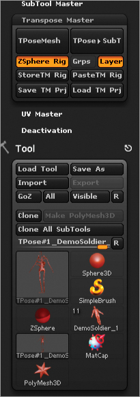
3. Make sure the ZSphere and Layer buttons are activated in Transpose Master. Click StoreTM Rig. This copies the rig that I have built for this model into memory.
4. Click DemoSoldier_1 and click the TPoseMesh button. Again, this merges all of the subtools into one and drops in a ZSphere.
5. Under the Transpose Master plug-in, click PasteTM Rig. This replaces the single ZSphere with the rig that you copied in step 3.
6. Activate the Bind Mesh button in the Tool Rigging subpalette.
7. Under Tool Layers, create a new layer. This creates a layer called Pose_TMask_Layer. You will store your first pose on this layer to be sent back to your DemoSoldier_1 with the multiple subtools.
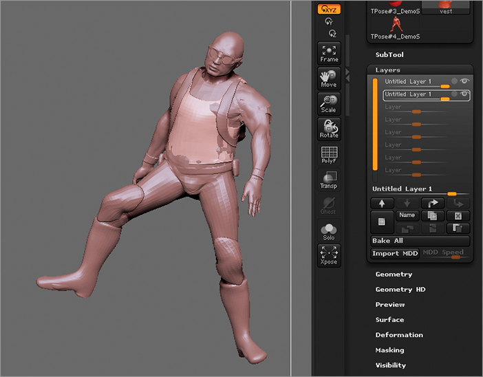
8. After you complete a pose, click the TPose SubT button. The pose is sent to the DemoSoldier_1 tool, but the pose is applied to a layer because you activated the Layer button in Transpose Master. Figure 7-31 shows how my crazy pose was sent to the tool and applied to the layer.
Figure 7-31: The pose is transferred to DemoSoldier_1 and applied to the layer.
9. In the Subtool palette, select each subtool and set the value for the layer to 0.
10. Now you’re ready to create a new pose. Just click the TPose#13_Demo soldier (you may have a different name) that you made when the TPoseMesh button was clicked in step 4. This is the version of the figure that you posed in step 4 (see Figure 7-32).
Figure 7-32: Click the mesh created with the rig.

11. By default, this mesh will automatically be put into Preview mode in the Tool Adaptive Skin subpalette.
12. Press the A hot key on the keyboard to bring back your ZSphere rigged version.
13. As you know, you created a layer for this first pose in the Tool Layer subpalette. Move the Pose_TMask_Layer to 0 so that your DemoSoldier is back to a neutral pose.
14. Create a second layer to store another pose on the rigged mesh. Create a second pose now. After you have the pose you’re looking for, click the TPose SubT button to send this second pose to DemoSoldier_1. This pose is automatically applied to the second layer of every subtool (see Figure 7-33).
Figure 7-33: The second pose is stored on a new layer.
Now just continue this process to keep creating new poses until you find the one you want.
Assigning Multiple Poses to the Timeline
Let’s put your poses into motion by adding each layer to the timeline. Then you can watch a movie of the character going from one pose to another. I saved the multiple-posed character as a project in the Chapter 7 Assets folder. The file is named TimelinePose.ZPR.
I also created a video of me walking through the process of storing the poses on a timeline. This video is called TimelinePose.mov in the Chapter 7 Videos folder.
1. Choose Movie TimeLine and then click the Show button (see Figure 7-34). The timeline appears above the ZBrush document.
Figure 7-34: Turn on the timeline in the Movie palette.

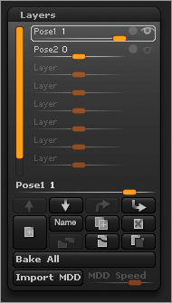
2. Select the first layer of the DemoSoldier subtool. Click the Name button in the Tool Layers subpalette and rename this Pose1. Rename every subtool with this layer-naming convention. See Figure 7-35.
Figure 7-35: Create two layers, naming the first one Pose1 and the second one Pose2.
3. With Pose1 selected in the Layer subpalette, the timeline also shows that Pose1 is selected (see Figure 7-36). Set Pose1 at 1 on the timeline and then click the front of the timeline to create a keyframe. If you see the word Camera next to the timeline, you do not currently have the layer selected, and any keyframes added to the timeline will be applied to the camera position.
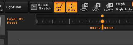
4. Now move the Pose1 layer to 0 and create another keyframe further down the timeline (see Figure 7-37). These two keyframes will not cause the DemoSoldier body to move out of Pose1 into no pose.
Figure 7-36: Click at the beginning of the timeline to create a keyframe.

Figure 7-37: Create another keyframe with Pose1 layer at 0.

5. Switch to the Pose2 layer, which will be set to 0. Figure 7-38 shows that the timeline also updates to Pose2. Notice the gray keyframes; these show where the keyframes were placed for Pose1.
6. Switch the body to the other pose and place a keyframe at the second gray keyframe (see Figure 7-39)
Figure 7-38: Switch to Pose2 to update the timeline. All keyframes that are placed will affect the Pose2 layer.
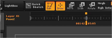
Figure 7-39: Place a keyframe where the second keyframe lies.
7. Turn the Pose2 layer to 1, and then create a new keyframe on the timeline (see Figure 7-40).
Figure 7-40: Create another keyframe on the timeline with Pose2 set at 1.

8. When you cycle through the timeline, your character will switch from one pose to the other.
9. Click on the ZBrush document. The timeline now reads Camera. Click once at the beginning of the timeline, and a second time anywhere else, to set what you want the camera to do when playing back the video.
10. Complete this action for every subtool so that the whole character will move smoothly. You can watch a movie of my character going through the poses in the Chapter 7 Videos folder. This video is called MultiplePoses.mov.
If you had more poses, you could continue this process down the timeline. You also could change the transition speed between each pose by just moving the keyframes closer along the timeline.
Exporting Blend Shapes from ZBrush to Maya
ZBrush is often used to create blend shapes for characters’ facial expressions. A few of the Artist Spotlights cover this subject in more detail, such as Marco Menco’s Artist Spotlight at the end of this chapter. I would like to walk you through a simpler approach using the layer system again and the preinstalled ZBrush plug-in, Maya Blend Shapes. Here are the steps:
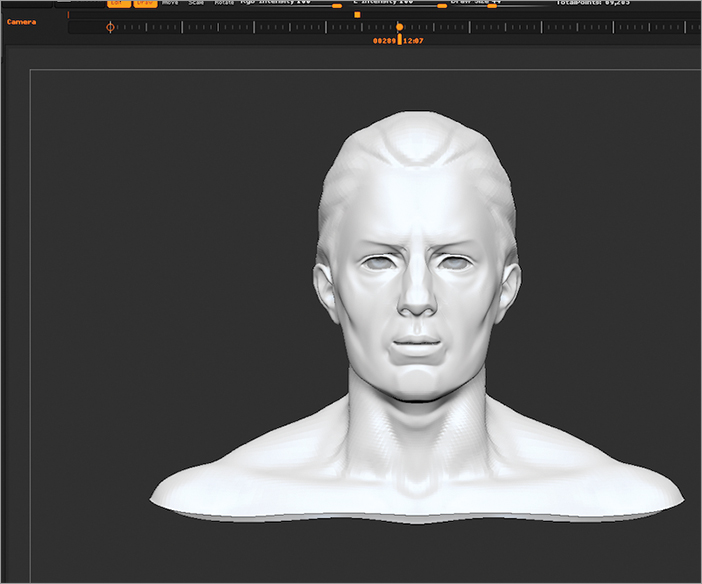
1. Select DemoHead.ZTL in LightBox from the Tool menu. Make sure it is in Edit mode on the ZBrush document. Now let’s give this guy some expressions.
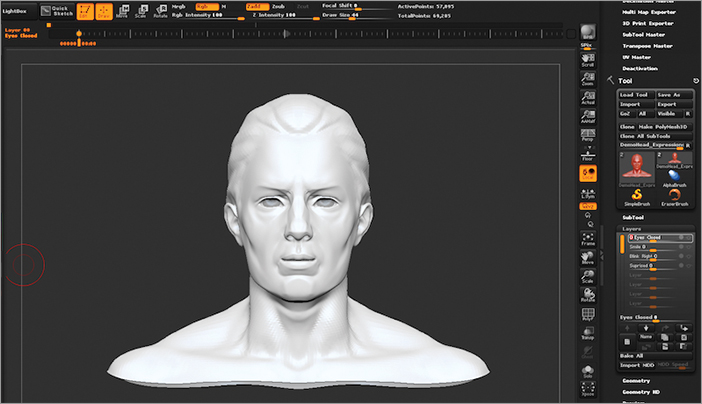
2. Create a new layer in the Tool Layers subpalette and name the layer Eyes Closed.
3. Add several more layers on the head, as shown in Figure 7-41. Notice that each expression is on its own layer.
Figure 7-41: Apply one expression per layer.

4. Before sending these layers over to Maya, test them with the timeline feature. Turn on the timeline again if it’s not already on by clicking Show in the Movie TimeLine subpalette.
5. Activate the camera track by clicking any open space on the ZBrush document, and then add two keyframes by clicking the timeline twice. See Figure 7-42.
Figure 7-42: Make two keyframes on the camera timeline before beginning to add keyframes for the layers.
6. Select the first layer of your DemoHead (in this example, this is Eyes Closed). If you wish to use my DemoHead, I have saved it in the Chapter 7 Assets folder as DemoHead_Expressions.ZTL.
7. With the Eyes Closed layer set to 0, create a keyframe at the beginning of the timeline. With the layer set to 0, the eyes will be open. You can see in Figure 7-43 where I am at this point.
Figure 7-43: Create a keyframe at the beginning of the timeline with the Eyes Closed layer set to 0.
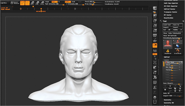
8. Now adjust the Eyes Closed layer to 1. This closes the eyes. Click another spot on the timeline to indicate where you want the eyes to be closed. Figure 7-44 shows where I am at this stage.
Figure 7-44: Turn the Eyes Closed layer to 1 and create another keyframe on the timeline.
9. Repeat this process for every layer of expressions. When you are finished, move along the timeline to see how your expressions are working.
If you do not like the looks of your expressions, you can turn that layer to 1 and click to the left of the eyeball to put the layer back into REC mode. Make your changes and then click to the right of REC to turn your eyeball back on. These changes will also be updated on the timeline.
When you are happy with your expressions, export them to Maya, which is easy with the Maya Blend Shapes plug-in for ZBrush.
10. Turn on All in the Maya Blend Shapes plug-in. This tells ZBrush to export all subtools into Maya.
11. With the DemoHead still selected, click the Export Blend Shapes button (see Figure 7-45).
Figure 7-46 shows that all layers import into Maya as blend shapes with the same names as the layers in ZBrush.
Figure 7-45: Click the Export Blend Shapes button to send your layers into Maya as blend shapes.
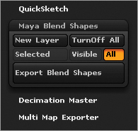
Figure 7-46: ZBrush layers imported into Maya as blend shapes
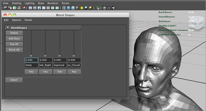
With all the layers coming over to Maya as blend shapes, you can see how easily you can create a really cool workflow, going back and forth between both applications to create a realistic animation.
Fast Mesh-Generating with Mesh Extract and Masking with the Clip Brushes
I do all my modeling in ZBrush, from low-poly base meshes to finished high-res sculpts. This allows me to fully concentrate on concept creation without having to readjust to different working environments and workflow paradigms of other software.

I would like to show a few of the workflows that I use to create my hard-surface objects within ZBrush. The following models have a fairly simple shape in order to emphasize the techniques and workflow that, when mastered, you can use to create shapes ranging from a simple table to the most complex spacecraft.
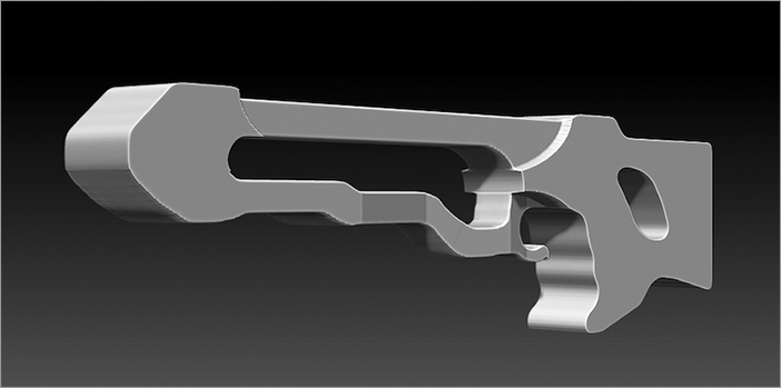
One of the fastest ways to generate a mesh is to extract one from a plane or from an existing mesh. In the next example, I will show how to use this technique in combination with a reference image. The following image is an example of what I created using this technique.
1. Select the Plane3D primitive in the tool palette in Edit mode and then click the MakePolyMesh3D button.
2. Choose Tool Geometry and click Divide four times, or use the shortcut Ctrl+D, so the plane has five subdivision levels.
3. Choose Texture Import to load a reference image of your choice. For this example, I loaded a gun image.
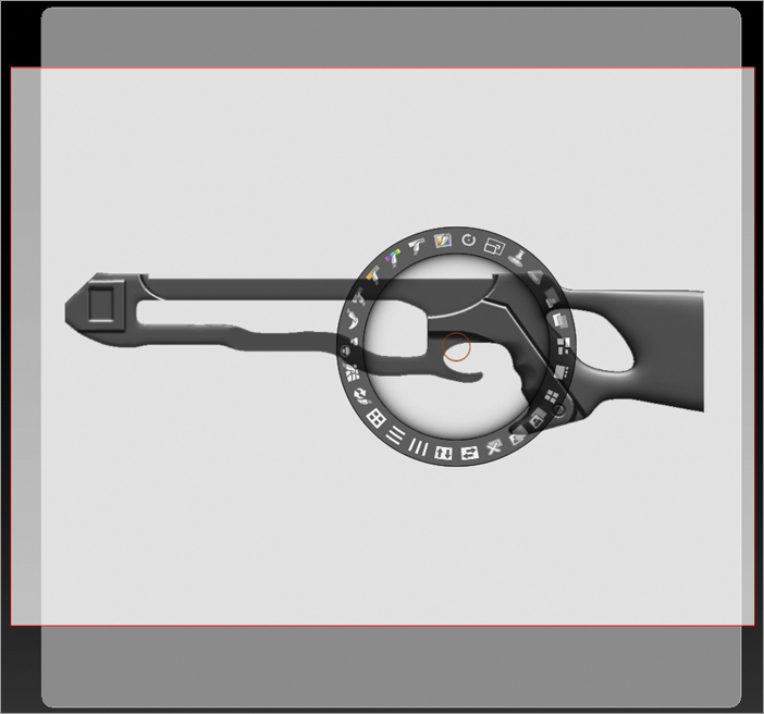
4. Press the +/- button you see in the following image to load the texture into Spotlight (Texture +/- button).
5. Use the Spotlight dial to adjust the position, size, and opacity of the image, as shown in the following image. Press Z to hide the Spotlight dial to switch into Spotlight Projection mode.
6. With the Standard brush selected, and with only RGB on at the top of the interface, draw your reference image on the plane by stroking over the image.
7. Using the reference image as a guide, use the masking brushes to mask off the shape you need. I used the MaskRect brush in the following image.
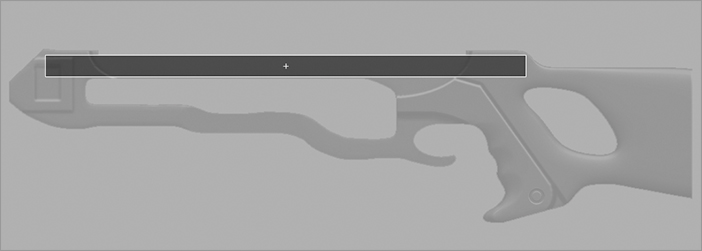
Continue to use the masking brushes to mask the rest of the gun off.
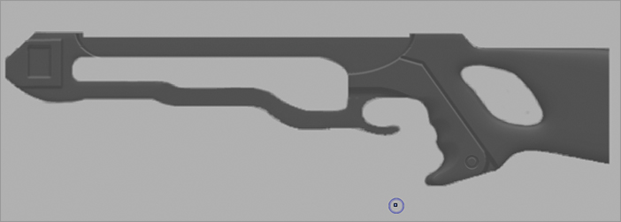
8. In the Tool SubTool subpalette, click Extract. This creates a new mesh based on the mask, as shown in the following image.
If needed, you can adjust the edge smoothness (E Smt), the surface smoothness (S Smt), and the thickness (Thick) before clicking Extract. After you see what you like, click the Accept button to create a subtool from the mask. Experiment with the slider settings to see their effect when extracting.
A technique I use a lot is to mask parts and then use the clipping brushes to create some detail.
9. Using one or more of the masking brushes, draw and invert if needed to get the shape you want (see the following image). Switch to a side view and use the ClipCurve brush to control both the depth and shape of the carved form.
10. Invert the mask and then switch to a side view; use the ClipCurve brush to control both the depth and shape of the carved form.
11. Create another mask like the following image.

12. Turn your view to the front and draw out a unique curve with the ClipCurve brush, as shown on the left of the following image. Your result will be something like the right side of the following image.
The following image shows the changes to the gun.
13. Continue the process of masking and extracting to create more pieces just like the following image. When you have enough pieces, use the ClipCurve brush to refine the gun. This technique of extracting is great because the new mesh created will follow the underlying surface perfectly.
There’s More
Geert has completed two more techniques that appear on the DVD in the Geert Melis folder. Enjoy the rest of his tips, and I encourage you to continue keeping an eye on Geert’s thread to see all the great hard-edge techniques he does with ZBrush.
Geert Melis lives and works in Belgium. He studied at the Royal Academy of Fine Arts in Antwerp and is employed as an art teacher and ZBrush Certified Instructor at De Kunsthumaniora—Antwerp. He was a beta tester for Pixologic on the PaintStop and UV Master plug-ins, ZBrush 3.5, ZBrush 4, and ZBrush 4R2.
The development of his personal project The Thin Veil of Reality can be followed in his Etcher_Sketcher thread at ZBrushCentral, www.zbrushcentral.com/showthread.php?78703-Etcher_Sketcher. It contains more than 100 sheets filled with tips and tricks on drawing and sculpting the human figure, concept drawing and sculpting, and working with ZBrush and PaintStop.
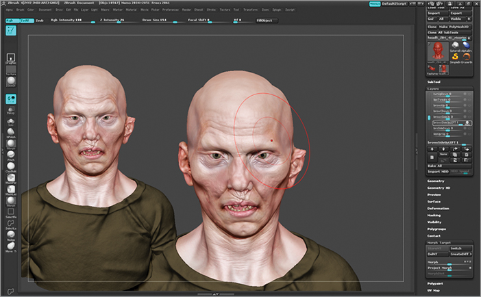
Using Layers and Project All to Work with Facial Expressions
The power of using the ZBrush layer system is that it lets you break up your model details into layers and lets you store the different morph targets of your model. You can exploit this feature by using it interactively to generate a library of facial expressions. I say interactively because you can store your morph in the layer and see your mesh deforming in real time by using the slider for each respective layer (see the following image).

1. Before you start to work on facial shapes, make sure you have all the subtools you need. For the head model that you are working on, you need the following:
- Your head model
- A duplicate of your head model
- Teeth/tongue (whatever mouth pieces you have)
- Eyeballs
As the title suggests, I use Project All quite a bit during the whole process, and that means that I interact between subtools.

2. Create a layer and then rename it right away so that you always know what you are focusing on while working. I rename the layer with the name of the muscle that I plan to work with, or with the name of the facial expression I want to store. Usually I use something such as muscle-base for the name of the layer on facial expressions because it allows me to collect a more varied range of targets that I’m going to combine in order to achieve specific expressions.
- To create a layer, click Tool Plus button.
- To rename the layer, click Tool Name.
- Make sure the layer is in Recording mode. Click the full circle on the same line of the layer you’re working on.
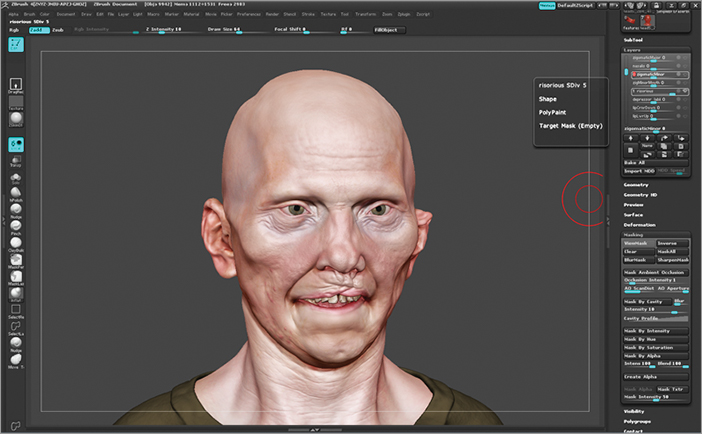
3. Now you begin the process of sculpting. You want to work on the zygomatic major (this will be the name of the layer) muscle of the cheek. Use the Move Topological brush, and make the brush size big enough to have a nice falloff on the movement of the skin. Then go to Subdivision level 1 in the Geometry subpalette (this also helps for a nice falloff). Now start moving the geometry from the fleshy part of the face along the length of the muscle to the cheek bone, where the muscle inserts. Keeping the wireframe visible helps you see what part of the mesh is moving and how (see the following image).

4. Now you can start moving up to the higher subdivisions and use the Nudge brush to refine the act of skin sliding. After you do the initial blocking of the shape in lower subdivisions, duplicate the head geometry and give the duplicated head a vibrant color. I like red.

5. At this point, it’s going to be clear where you’ve lost volumes or if you accidentally changed the morphology of the skull. You need to reproject those volumes where the bones are. So hide all subtools but the two heads: the one that you’re working on and its duplicate.
You’re still working on lower subdivisions, so you avoid projecting high-frequency details onto areas that have now moved. At the end of the process, you want to achieve a nice skin-sliding-over-bones effect. That means you need the high-frequency details to remain untouched and the UV to remain intact.
6. Select the MaskPen brush by holding down the Ctrl key and then paint-mask over the cheek bones. Click Tool SubTool and click ProjectAll.
7. Tweaking the distance or the blur usually helps to achieve better results. However, in general, if you didn’t move the geo too far from the duplicate mesh, you won’t need to tweak anything (see the following image).

8. Now you can start to play with the Layer slider that you have been sculpting on to see how the skin moves. If the movement doesn’t look realistic enough, go to the higher subdivisions and play a bit with the Nudge brush and keep sliding the skin more where it’s needed.
You can hide the duplicate head and make all the other subtools visible so that you see whether you’re crashing into some of them while the expression is happening. Keep sliding the layer and refining the movement until you’re happy with it, as I did in the next image.

9. Now you can think about the details that the skin movement is supposed to create on a human face. So switch between one subdivision and another as necessary to sculpt wrinkles and bulge details by using the DamStandard and Inflate brushes in ZBrush’s main Brush palette (see the following image).

10. Sculpt a library of expressions for each layer. That is, keep repeating the preceding process until you cover the range of movements that face muscles can make. Then you can pick and choose several layer sliders to get the expression you want, as shown in the following image.
11. Now you really need to give the shapes a run by starting to pull the sliders around and then trying to combine them to see whether you can achieve believable expressions (see the following image). Try spinning the head around and looking at it from different angles so that you can see whether the combination makes the skull lose its volumes.

12. Most of the time when you combine the layers, areas will crash into the other subtools, such as the teeth. This is due to the nature of the layer, which has a linear interpolation. Create a new layer called lipsTweak. This is basically a layer that works as an in-between for other layers. Now when you turn on one or more combinations of shapes, you also pull that tweaks layer to fill the loss of volume that happened because of the linear interpolation. As shown in the following image, for instance, I used the lipsTweak layer to avoid having the lower lip crash into the teeth subtool.
13. The specific head you’re working on has a fairly flat face, so you can avoid making many layer tweaks. You can more easily avoid geometry colliding into other subtools if most of your muscle movement happens on the same plane of the face. For instance, if you were working with the face of a wolf, or a creature with a longer muzzle, or a more three-dimensional face, you would have to create many more layers for tweaks.
14. So far you’ve worked in symmetry. However, when it becomes necessary, you can start to split the layers into left- and right-side layers of face movement. You could have created layers with individual movement (such as right eye closed, left eye closed) instead of having the eyes closed since the beginning. I chose not to work with this approach because of speed. The face can stay asymmetrical even if you work with Symmetry on, as long as you turn Symmetry off when you add major asymmetrical details.
15. To split the layers into left and right sides, simply store a morph target of the default post: click Tool StoreMT.
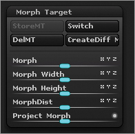
16. Duplicate the layer you want to split and rename it according to the side that will define the shape—for example, browsSideUpLEFT. Now you can simply use the Morph brush and paint out one part of the face. Duplicate the original, symmetrical layer again and rename it browsSideUpRIGHT. Then use the Morph brush on the right side and paint out the other side of the face. The following image shows how I used one layer to create two separate layers for the brow. Keep doing this for all the shapes you need to split.
Where I work currently at Image Engine Design, we have a script that will separate the two sides of the symmetrical shapes automatically in Maya by using one attribute map.
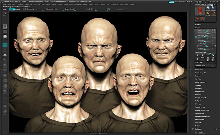
17. The last thing you have left to do is to create expressions! In the next image, you can see all the expressions I have started to create with the ZBrush layer system.
Marco Menco grew up in a big Italian family at the center of the Adriatic coast of Italy. He spent his youth admiring artists such as Gustave Dore and the Italian Renaissance masters.
Between school and work, he has always focused on improving his artistic skills. His experience includes illustration, comic drawing, 3D modeling and texturing, and concept designing for film and television. In the past, he also has worked as a traditional sculptor for theater scenographies.
When he finally decided to be an artist for life, Marco entered the Academy of Fine Arts and in 2007 obtained his bachelor’s degree. The time he spent on preparing his final thesis was really important for him because it allowed him to finally accomplish several personal pieces of artwork. Of course, his passion for Gustave Dore led him to work on a series of concept illustrations based on Dante’s The Divine Comedy: Inferno. Marco is still in the process of reinventing Dante’s Inferno, which he decided would be his lifelong project.
After completing the Academy in 2007, Marco moved to Vancouver, British Columbia, where he works as a senior creature artist at Image Engine Design.
At the moment, his attention is captured by facial expressions and edge flow for high-performance geometries. The most recent project he worked on was The Thing, the prequel, for which he modeled and sculpted most of the complex creatures present in the sequences. He also created libraries of facial expressions and contributed to the development of animated displacement maps for enhancing facial details for the Image Engine pipeline.