
Laddered Multilevel DC/AC Inverters Used in Solar Panel Energy Systems
Multilevel DC/AC inverters have various structures and many advantages. Unfortunately, most existing inverters contain too many components (independent and floating batteries and sources, diodes, capacitors, and switches) making production cost high and conversion efficiency low. We introduced four kinds of inverters: laddered multilevel DC/AC inverters, super-lift modulated inverters, switched capacitor multilevel DC/AC inverters, and switched inductor multilevel DC/AC inverters in Chapters 10,11,12,13 that are new developments in this area. Their simple structures and straightforward operations are completely different from existing inverters. They have been successfully applied in solar panel energy systems [1]. These inverters will attract worldwide attention and be applied in other renewable energy systems.
Comparing with PWM DC/AC inverters, multilevel DC/AC inverters have many advantages such as lower switching flying voltage (from one level to next level), di/dt, and dv/dt, switching frequency, and THD. Unfortunately, most existing multilevel inverters contain too many components (independent and floating batteries and sources, diodes, capacitors, and switches). For example, a diode-clamped inverter, also called the neutral-point clamped (NPC) inverter, has m = (2b + 1) levels and the components needed are
• 4b switches
• 2b capacitors
• (4b - 2) diodes
where m is the level number, which is always an odd number, and b is the stage number (from the neutral point to the top point) [1,2,3]; a linear H-bridged inverter [2,2,4] has m = (2b + 1) levels and the components needed are
• b floating batteries
• 4b switches
• 4b diodes
Figure 10.1 shows a five-level NPC inverter and a three-bridge inverter.
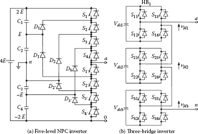
FIGURE 10.1
Example inverters.
From Figure 10.1, we can see that a 5-level NPC inverter has a 4E battery (or 2 × 2 E batteries), 8 switches, 14 diodes, and 4 capacitors; a 7-level linear three-bridge inverter contains three floating batteries (Vdc1 = Vdc2 = Vdc3 = E), 12 diodes, and 12 switches.
In this chapter, we will introduce laddered multilevel DC/AC inverters, which have a simple structure and straightforward operation and are a new development in the DC/AC inverter area. We will begin with a brief description on progressions.
In mathematics, a progression is a series of numbers or quantities in which there is always the same relation between each quantity and the one succeeding it. We introduce several progressions in this section. In our laddered multilevel inverter design, we assume that in all progressions the value of the general ith term is Vi, and the value of the first term V1 is 1.
10.2.1 Arithmetic Progressions
For all arithmetic progressions, the difference between the consecutive terms is constant. Some special cases are
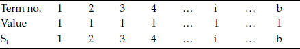
• Unit progression, where all terms are equal to 1
• Natural progression, where all terms are natural numbers
• Odd number progression, where each term is odd-numbered
We define the value of the first term as V1, the value of the general ith term as Vi, and the difference as d. Therefore, the value of the general term Vi is
(10.1) |
The sum of the terms from the first term to the ith term is Si,
(10.2) |
The unit progression is listed in Table 10.1, where d = 0. We assume that the last term is b with value Vb. From Equation (10.2), the sum of the terms Si from 1 to the ith term is i.
10.2.1.2 Natural Number Progression
The natural number progression is listed in Table 10.2, where the difference d = 1 and the sum of the terms Si from 1 to the ith term is .
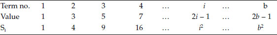
10.2.1.3 Odd Number Progression
The odd number progression is listed in Table 10.3, where difference d = 2 and the sum of the terms Si from 1 to the ith term is Si = i2.
TABLE 10.2
Natural Number Progression
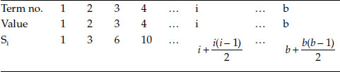
TABLE 10.3
Odd Number Progression
All geometric progressions have a constant ratio between successive terms. Two special series are
• Binary progression, where the ratio between successive terms equals 2
• Trinary progression, where the ratio equals 3
We define the ratio as r. Therefore, the value of the ith term Vi is
(10.3) |
The sum of the terms Si is
(10.4) |
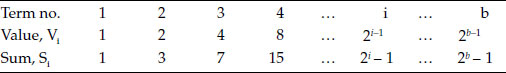
The binary progression is listed in Table 10.4. Since the ratio r = 2, the sum of the terms Si from 1 to the ith term is .
10.2.2.2 Trinary Number Progression
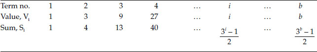
The trinary progression is listed in Table 10.5. Since the ratio r is 3, the sum of the terms Si from 1 to the ith term is .
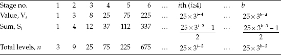
Two new progressions are designed for laddered multilevel inverters. They are
• Luo progression
• Ye progression
The Luo progression is a new series that is different from any existing methods such as arithmetic and geometric progressions. The value of each term starting from the third term is twice the sum of the all previous terms plus 1:
(10.5) |
The sum of the terms from the first term to the ith term is Si:
(10.6) |
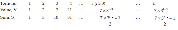
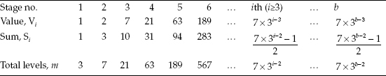
The Luo progression is listed in Table 10.6. The sum of the terms from 1 to the ith term Si is with i ≥ 2.
The Ye progression is another novel progression (series). The value of each term starting from the fourth is twice the sum of the all previous terms plus 1:
(10.7) |
where u(i - 2) is the unit-step function:
(10.8) |
The sum of the terms from the first term to the ith term is Si,
(10.9) |
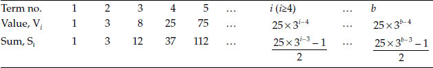
The Ye progression is listed in Table 10.7. The sum of the terms from 1 to the ith term Si is with i ≥ 3.
10.3 Laddered Multilevel DC/AC Inverters
Before introducing laddered multilevel DC/AC inverters in this section, we start with some special switches.
The toggle switch is shown in Figure 10.2a, which is also called the one-pole two-throw (1P2T) switch. The switch has one wiper pole (W) and two contact positions “a” and “b.” When the switch is on the wiper pole, it is linked to position “a,” otherwise to position “b.”
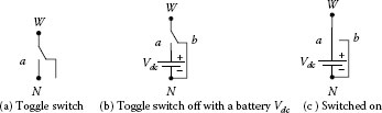
FIGURE 10.2
The toggle switch with a battery Vdc.
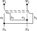
FIGURE 10.3
A two-pole two-throw (2P2T) switch.
The terminal voltage of VWN equals Vdc during switch-on as shown in Figure 10.2c, and 0 during switch-off as shown in Figure 10.2b.
A change-over switch is shown in Figure 10.3, which is also called the two-pole two-throw (2P2T) switch. It reverses the output voltage from the input voltage. If the input voltage is VW1W2 and the output voltage is VN1N2, we have
(10.10) |
A band switch is shown in Figure 10.4, which is also called the one-pole multi-throw (1PMT) switch. It has one wiper pole (W) and multiple contact positions “0,” “1,” “2,” …, “m.”
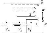
FIGURE 10.4
The band switch with M throws.
We assume that there are m voltage sources linked to the bands as V1, V2, …, Vm, as shown in Figure 10.4. The terminal voltage of VWN equals various source voltages:
(10.11) |
10.3.2 General Circuit of Laddered Inverters
The general circuit of laddered inverters is shown in Figure 10.5. It is symmetrical about the neutral point N; that is, there are two wings, positive and negative. Each wing has b sets of the toggle-switches Si and batteries Vdci, where i = −b, -(b - 1), …, -2, -1, 1, 2, …, b - 1; b is the ladder stage number; m is the total level number, and i is the ith set number. The positive wing contains b sets in all, and the negative wing has the same number of sets by symmetry. Therefore, we have
(10.12) |
To simplify the analysis, we assume a purely resistive load R.
10.3.3 Linear Laddered Inverters (LLIs)
If all DC voltages Vdci in the laddered inverter shown in Figure 10.5 are the same voltage E, the result is a linear laddered inverter (LLI). This ladder was constructed following unit progression. The output voltage Vout has m levels and m = 2b + 1.
(10.13) |
The operation status:
Vout = bE: All positive wing switches on (others are off)
Vout = (b–1)E: Switches S1 – Sb-1 are on (others are off)
……
Vout = 2E: Switches S1 – S2 are on (others are off)
Vout = E: only Switch S1 is on (others are off)
Vout = 0: All Switches are off
Vout = −E: only Switch S-1 is on (others are off)
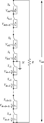
FIGURE 10.5
The general circuit of laddered inverters.
Vout = –2E: Switches S-1 – S-2 are on (others are off)
……
Vout = – (b –1)E: Switches S-1 – S-(b-1) are on (others are off)
Vout = – bE: All negative wing switches on (others are off)
We obtain m = 2b + 1 levels. For example, if b = 3, we have the total level number m = 7. The output voltage waveform is shown in Figure 10.6.
10.3.4 Natural Number Laddered Inverters (NNLIs)
If all DC voltages Vdci in Figure 10.5 are iE, the inverter becomes a natural number laddered inverter (NNLI). This ladder was constructed following the natural number progression. The output voltage Vout has m levels, where m = b2 + b + 1 (refer to Table 10.2):
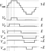
FIGURE 10.6
A seven-level output voltage waveform.
(10.14) |
The operation status:
• E: All positive wing switches on (the others are off)
• E: Switches S2–Sb are on (the others are off)
• ……
• Vout = 2E: only Switch S2 is on (others are off)
• Vout = E: only Switch S1 is on (others are off)
• Vout = 0: All Switches are off
• Vout = −E: only Switch S-1 is on (others are off)
• Vout = −2E: only Switch S-2 is on (others are off)
• ……
• E: Switches S-2 - S-b are on (others are off)
• E: All negative wing switches on (others are off)
We obtain m = b2 + b + 1 levels. For example, if b = 3, we have the total level number m = 13.
10.3.5 Odd Number Laddered Inverters (ONLIs)
If we set all DC voltages Vdci in the positive wing to be (2i- 1) E, as shown in Figure 10.5, we have the odd number laddered inverter (ONLI). This ladder was constructed following an odd number progression. The output voltage Vout has m levels, and m = 2b2 + 1 from Table 10.3:
(10.15) |
The operation status:
• Vout = b2E: All positive wing switches on (others are off)
• Vout = (b2 − 1)E: Switches S2 – Sb are on (others are off)
• ……
• Vout = 3E: only Switch S2 is on (others are off)
• Vout = 2E: Switches S2 – S−1 are on (others are off)
• Vout = E: only Switch S1 is on (others are off)
• Vout = 0: All Switches are off
• Vout = −E: only Switch S−1 is on (others are off)
• Vout = −2E: Switches S−1 – S−2 S1 are on (others are off)
• Vout = −3E: only Switch S−2 is on (others are off)
• ……
• Vout = (b2 − 1)E: Switches S−2 − S−b are on (others are off)
• Vout = − b2E: All negative wing switches on (others are off)
We obtain m = 2b2 + 1 levels. For example, if b = 3, the total level number m = 19.
10.3.6 Binary Laddered Inverters (BLIs)
If we set all DC voltages Vdci in Figure 10.5 to be the voltage (2i – 1) E, we obtain the binary laddered inverter (BLI). This ladder was constructed following a binary progression. The output voltage Vout has m levels, where m = 2b+1 -1 from Table 10.4 The above DC voltages Vdci are binary voltages:
(10.16) |
The operation status:
• Vout = (2b-1)E: All positive wing switches on (others are off)
• ……
• Vout = 3E: Switches S1 – S2 are on (others are off)
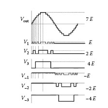
FIGURE 10.7
A fifteen-level output voltage waveform.
• Vout = 2E: only Switch S2 is on (others are off)
• Vout = E: only Switch S1 is on (others are off)
• Vout = 0: All Switches are off
• Vout = −E: only Switch S-1 is on (others are off)
• Vout = −2E: only Switch S-2 is on (others are off)
• Vout = −3E: Switches S-1 – S−2 are on (others are off)
• ……
• Vout = − (2b – 1)E: All negative wing switches on (others are off)
We achieved m = 2b+1 − 1 levels. For example, if b = 3, we have an m = 15 levels output voltage waveform as shown in Figure 10.7.
10.3.7 Modified Binary Laddered Inverters (MBLIs)
The modified binary laddered inverter (MBLI) is shown in Figure 10.8. We used a change-over (two-pole two-throw) switch to exchange the output voltage polarity, and saved half of the batteries and switches used in the negative wing.
For the operation status and output voltage waveform, see Section 10.3.6 and Figure 10.7. The output voltage Vout has m levels, where m = 2b+1 – 1.
10.3.8 Luo Progression Laddered Inverters (LPLIs)
For the Luo progression defined in Section 10.3.2.1,
(10.17) |
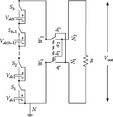
FIGURE 10.8
The modified binary laddered inverters.
the total level m, as shown in Table 10.8, is
(10.18) |
If we construct a ladder with 4 stages (b = 4) in both wings, from Table 10.8 we can obtain 63 levels (m = 63) in all. If the level unit is “E,” the operation status is as shown below:
• Vout = 31E: All positive wing switches on (others are off)
• ……
• Vout = 4E: Switches S3, S-1, S-2 are on (others are off)
• Vout = 3E: Switches S1 and S2 are on (others are off)
• Vout = 2E: only Switch S2 is on (others are off)
• Vout = E: only Switch S1 is on (others are off)
• Vout = 0: All Switches are off
• Vout = −E: only Switch S-1 is on (others are off)
• Vout = −2E: only Switch S-2 is on (others are off)
• Vout = − 3E: Switches S-1 and S-2 are on (others are off)
• V out = − 4E: Switches, S-3, S1 and S2 are on (others are off)
• ……
• Vout = − 31E: All negative wing switches on (others are off)
10.3.9 Ye Progression Laddered Inverters (YPLIs)
For the Ye-progression defined in Section 10.3.2.2,
(10.19) |
the total level m, as shown in Table 10.9, is
(10.20) |
From Table 10.9, if we construct a ladder with 4 stages (b = 4) in both wings, we can obtain 75 levels (m = 75). If the level unit is “E,” the operation status is as shown below:
• Vout = 37E: All positive wing switches on (others are off)
• ……
• Vout = 4E: Switches S1 and S3 are on (others are off)
• Vout = 3E: only Switch S2 is on (others are off)
• Vout = 2E: Switches S2 and S-1 are on (others are off)
• Vout = E: only Switch S1 is on (others are off)
• Vout = 0: All Switches are off
• Vout = –E: only Switch S-1 is on (others are off)
• Vout = –2E: Switches S-2 and S1 are on (others are off)
• Vout = −3E: only Switch S-2 is on (others are off)
• Vout = −4E: Switches S-1 and S-2 are on (others are off)
• ……
• Vout = −37E: All negative wing switches on (others are off)
10.3.10 Trinary Laddered Inverters (TLIs)
If we set the DC voltages Vdci in Figure 10.5 to be trinary,
(10.21) |
the inverter becomes a trinary laddered inverter (TLI). The total level number m = 3b. For example, if b = 4, we have the total level number m = 81. The operation status is shown below:
• Vout = 40E: All positive wing switches on (others are off);
• ……
• Vout = 3E: only Switch S2 is on (others are off)
• Vout = 2E: Switches S2 and S-1 are on (others are off)
• Vout = E: only Switch S1 is on (others are off)
• Vout = 0: All Switches are off
• Vout = −E: only Switch S-1 is on (others are off)
• Vout = −2E: Switches S1 and S-2 are on (others are off)
• Vout = −3E: only Switch S-2 is on (others are off)
• ……
• Vout = −40E: All negative wing switches on (others are off)
10.4 Comparison of All Laddered Inverters
We introduced eight types of laddered inverters in Section 10.3. Table 10.10 shows a comparison of them with two other inverters, where the abbreviations are as follows:
• LLI—Linear laddered inverter
• NNLI—Natural number laddered inverter
• ONLI—Odd number laddered inverter
• BLI—Binary laddered inverter
TABLE 10.10
Comparison of All Laddered Inverters and Other Inverters
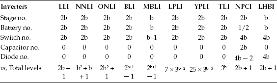
• MBLI—Modified binary laddered inverter
• LPLI—Luo progression laddered inverter
• YPLI—Ye progression laddered inverter
• TLI—Trinary laddered inverter
• NPCI—Neutral-Point clamped inverter
• LHBI—linear H-bridged inverter
For example, if b = 3, the level numbers for each inverter are shown in Table 10.11.
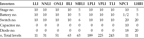
When b = 5, the level numbers for each inverter are listed in Table 10.12, showing the extraordinary increase in the level numbers achieved and fewer number of components used compared to those in Table 10.11, especially for the trinary ladder inverter (TLI), Ye progression laddered inverter (LPLI), and Luo progression laddered inverter (LPLI).
TABLE 10.11
Comparison of Inverters (if b = 3)
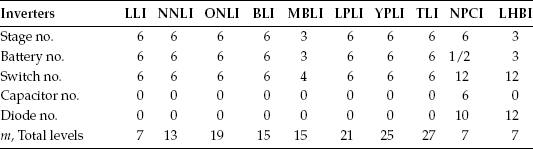
TABLE 10.12
Comparison of Inverters (if b = 5)
10.5 Solar Panel Energy Systems
The sun is a star in the universe. The earth is a planet, and flies in an oval orbit surrounding the sun. The sun is located at a focus of the oval orbit as shown in Figure 10.9 [4,5,6,7,8,9]. The average distance between the sun and earth is about 150 Mkm (150,000,000 kilometers). The sun radiates 3.8 × 10²⁰ MW of energy into space. Earth receives 174 × 109 MW from the sun.
The solar panel is constructed with a solar cell (or photovoltaic cell), the technology of which embraces broad multidisciplinary subject areas. It converts solar energy into electricity by the photovoltaic effect. Briefly, solar cells are divided into two groups: monocrystalline and multicrystalline silicon wafers. Figure 10.10 shows a monocrystalline silicon wafer solar cell.
The solar panel shown in Figure 10.11 is assembled with a few solar cells. The theoretical power curve for a solar panel system is shown in Figure 10.12. The current is nearly constant in the low-voltage region. When the input voltage reaches 16.2 V, the input current sharply reduces to zero. The curve is the output power with its maximum power point (MPP) at 132 W.
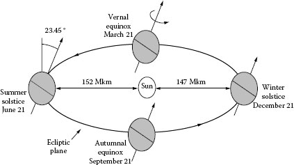
FIGURE 10.9
The sun and earth. (From Gilbert M. Masters 2004. Renewable and Efficient Electric Power Systems. New York: John Wiley & Sons. With permission.)
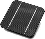
FIGURE 10.10
A monocrystalline solar cell.

FIGURE 10.11
A solar panel.
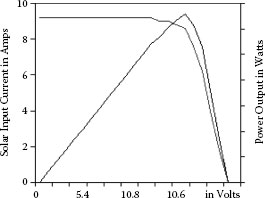
FIGURE 10.12
The theoretical system power curve.
We set the voltage unit E = 16.2 V. It is easy to construct the batteries for a BLI:
• Vdc1 = | Vdc-1 | = E = 16.2 V
• Vdc2 = | Vdc-2| = 2E = 32.4 V
• Vdc3 = | Vdc-3 | = 4E = 64.8 V
Another setting to construct the batteries for an LPLI is the following:
• Vdc1 = | Vdc-1 | = E = 16.2 V
• Vdc2 = | Vdc-2| = 2E = 32.4 V
• Vdc3 = | Vdc-3 | = 7E = 113.4 V
10.6 Simulation and Experimental Results
We use a BLI with b = 3 to do the simulation. The output voltage has 15 levels. The simulation and corresponding experimental results are shown in Figures 10.13 and 10.14, respectively.
We use an LPLI with b = 3 to do the simulation again. The output voltage has 21 levels. The simulation result is shown in Figure 10.15, and corresponding experimental result is shown in Figure 10.16.
Furthermore, we use the circuits for 41-level and 51-level inverters to do the simulation again. Their output voltages have 41 and 51 levels, respectively. Their simulation results are shown in Figures 10.17 and 10.19. Their corresponding experimental results are shown in Figures 10.18 and 10.20.
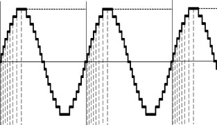
FIGURE 10.13
The simulation result of a fifteen-level BLI.
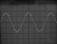
FIGURE 10.14
The experimental result of a 15-level BLI.
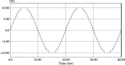
FIGURE 10.15
The simulation result of a 21-level LPLI.
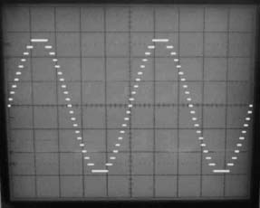
FIGURE 10.16
The experimental result of a 21-level LPLI.
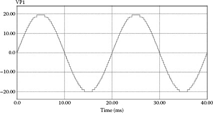
FIGURE 10.17
The simulation result of a 41-level inverter.
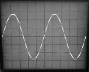
FIGURE 10.18
The experimental result of a 41-level inverter.
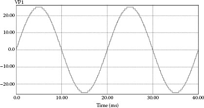
FIGURE 10.19
The simulation result of a 51-level inverter.
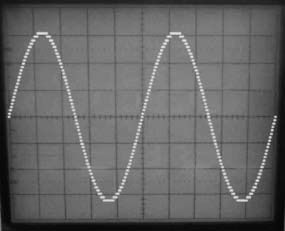
FIGURE 10.20
The experimental result of a fifty-one level inverter.
1. Luo F. L. 2011. Laddered multilevel DC/AC inverters used in solar panel energy systems. (invited keynote). Proc. Int. Forum on the Energy Planning and Green Power Organization, TaoYuan, Taiwan, pp. 1–25.
2. Luo F. L. and Ye H. 2010. Power Electronics: Advanced Conversion Technologies. Boca Raton, FL: Taylor & Francis.
3. Muhammad H. Rashid 2011. Power Electronics Handbook (3rd edition). Boston: Butterworth-Heinemann.
4. Gilbert M. Masters 2004. Renewable and Efficient Electric Power Systems. New York: John Wiley & Sons.
5. Rashid, M. H. 2003. Power Electronics: Circuits, Devices and Applications (3rd-edition). New Jersey: Prentice Hall.
6. Labouret A. and Villoz M. 2010. Solar Photovoltaic Energy, the Institution of Engineering and Technology. New Jersey: Prentice Hall.
7. Kalogirou S. A. 2009. Solar Energy Engineering Processes and Systems. San Diego: Academic Press.
8. Tagare D. M. 2010. Electricity Power Generation. New York: IEEE Press.
9. Kissell T. E. 2010. Introduction to Solar Principles. New Jersey, USA Prentice Hall.