Chapter 5. VFX Techniques I: Basic Integration VFX
Lighting is, by far, one of the most critical components in creating a photorealistic VFX shot. When creating the elements to be integrated into a VFX shot, whether CG or live action (filmed against a bluescreen or greenscreen), matching all the VFX lighting cues covered in Chapter 1 will be the deciding factor that makes all the difference between a VFX effect that looks seamless and real (as in Figure 5.1) or one that looks like a poor attempt or “pasted on” garbage (as in Figure 5.2).
Figure 5.1. A well-lit 3D object, integrated into a live action plate

Figure 5.2. A poorly lit object, not integrating well at all due to the mismatched lighting

Although many artists feel a disconnect between the lighting of live action elements filmed in front of a keyable background and the lighting of a 3D CG model rendered in a 3D application, the strategies and techniques used to light both components of a good seamless VFX shot are actually identical.
CG/VFX Lighting and Integration
The first step in creating excellent lighting for a VFX integration is not actually doing any lighting at all, but carefully analyzing the image, footage, or plate into which the element will be composited or integrated. When analyzing a background plate, you should ask yourself the following questions, take note of the answers, and figure out what you need to do to make your lighting match:
• Where is the main source of lighting in the scene coming from?
Key light placement, distance, and direction
• What is the quantity of the main light source?
Key light intensity level
• What is the quality of the main light source?
Key light harshness or softness
Shadow density and falloff
Key light color and temperature
• Is there any fill or secondary lighting in the scene?
Placement, distance, and direction
Intensity
Shadow density and falloff
Color and temperature
• Is there any rim, highlight, or back lighting in the scene?
Placement, distance, and direction
Intensity
Shadow density and falloff
Color and temperature
• Are there any interactive or moving lights in the scene?
Placement, distance, and direction
Intensity
Shadow density and falloff
Color and temperature
• Are there any special shadowing considerations in the scene?
Size, shape, and type (tree leaves, window mullion, rain, shadows from interactive scene elements, and so on)
Placement, distance, and direction
Intensity
Shadow density and falloff
Color and temperature
Once you have carefully analyzed the scene’s lighting, it’s time to light the foreground element that you want to film and integrate into the scene.
Method and Technique for VFX Element Lighting
Whether you are integrating a live action element (which was filmed in front of a blue- or greenscreen) or a 3D CGI element (created in your 3D application of choice), the method and procedure for lighting these elements are the same:
1. First, kill all of the light in the scene! Yes, you read that right. Although many artists tend to start with setting an ambient light level, that method inadvertently leads to having to add more and more lights, leading to over lighting and light spill contamination (lights spilling onto areas where they are not wanted or needed). Ideally, your scene should be completely dark or black. In a 3D computer graphics application, killing the lights simply means turning off all lights in the scene and setting the ambient intensity to 0%.
2. Make sure to have your element adequately far from your background (if shooting a live bluescreen/greenscreen element). Adequately means it’s far enough away that light projected onto the background won’t reflect, or spill, onto the foreground subject. Flags are devices used in lighting to block light, cast shadows, provide negative/dark fill, or protect the lens from a flare. You can use flags or curtains or curtains to block off foreground lights from contaminating the background and are very helpful when lighting small areas. Ideally, when your foreground is lit and the lighting on the background is turned off, the background should be completely black (as in Figure 5.3). When the background lights are turned on and the foreground lights are turned off, the foreground should be completely black and silhouetted against the bright and evenly lit background (as shown in Figure 5.4) with no spill or cross contamination of either. Professional lighting directors affectionately refer to this as “wrangling the beam.”
Figure 5.3. Foreground object lit with background lights turned off

Figure 5.4. Foreground object’s lights off and silhouetted against lit background with no spill or contamination

3. Next, you will place your key light (or main light source). From your careful examination of the background image (and the tips and tricks covered in Chapter 1), you should have a good idea of where to place your key light, at what height and angle, what type or quality of light it should be (harsh or soft), and its basic color and intensity (or quantity), as shown in Figure 5.5.
Figure 5.5. Object lit with key light only

Tip
A great trick to getting excellent matched lighting results is to run a “feed” from your camera into a real-time keying application that can do either real-time full, or rough, key extractions over a sample of your background. A few examples of these include plugins for compositing applications, such as Frischluft’s Lensfeed (www.frischluft.com), and even standalone stopframe animation software, such as AnimatorHD.
4. Once your key light is in position and set, it’s time to set up any fill or bounce lighting affecting the object you are filming. Again, by carefully analyzing the plate, you should be able to see where bounced/reflected lighting is filling in and lighting up (lifting) the shadow (or shadow density) levels. You should also have a good idea of where to place your fill lights, at what heights and angles, what type or quality of lights they should be (harsh or soft), and the basic color and intensity of each. You should perform constant monitoring and comparison, checking to make sure that the lighting and shadow levels, direction, quality, quantity, and color continue to match the reference as each light is added and adjusted (see Figure 5.6).

Note
It is very common to have more than one, or even many, fill lights in a scene. In an exterior scene, fill lights could emulate the light being bounced off of the sky and clouds, ground, nearby walls or objects, and so on.
Tip
It is extremely important while adding each light to take great care to isolate these lights’ output and avoid each of these lights spilling onto or contaminating the background.
5. After adding your fill lighting, place any rim or highlight lights (Figure 5.7), taking great care that these rim lights do not spill or reflect anywhere except where they are directed. Because these lights are commonly high-intensity lights, take great care that flags used to block the lights from spilling or causing lens flares don’t inadvertently reflect and backspill light onto the background or backdrop (this is also common with lights that aren’t completely light sealed on the back side of the lamp housing).

6. Finally, once your element is lit to match the lighting and shadows in the background footage or live action plate, it’s time to light your background or backdrop. There are many theories about the best way to light a backdrop, including specific light meter readings to ascertain specific exposures. I find that as long as you’ve carefully and correctly done the first five steps in this exercise and have perfectly isolated your foreground and background lighting to contain no spill or cross contamination, simply lighting the background with even diffuse light to a normal exposure level will yield excellent results, as shown in Figure 5.8.
Figure 5.8. Fully lit object and background with no spill contamination

Tip
Many people recommend keeping your bluescreen or greenscreen exposed one F-stop over. Although this does tend to make keying easier, it also increases on-set lighting and frequently results in having to add more and more light to the foreground, eventually (like trimming your hair too short on one side, then having to trim the other side more, back and forth, again and again) resulting in over-lighting the set.
2D Motion Tracking and CG Integration
One of the most basic and most commonly needed VFX is the integration of a filmed bluescreen/greenscreen or 3D CG–rendered element into a 2D motion-tracked live action plate.
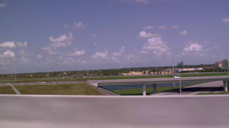
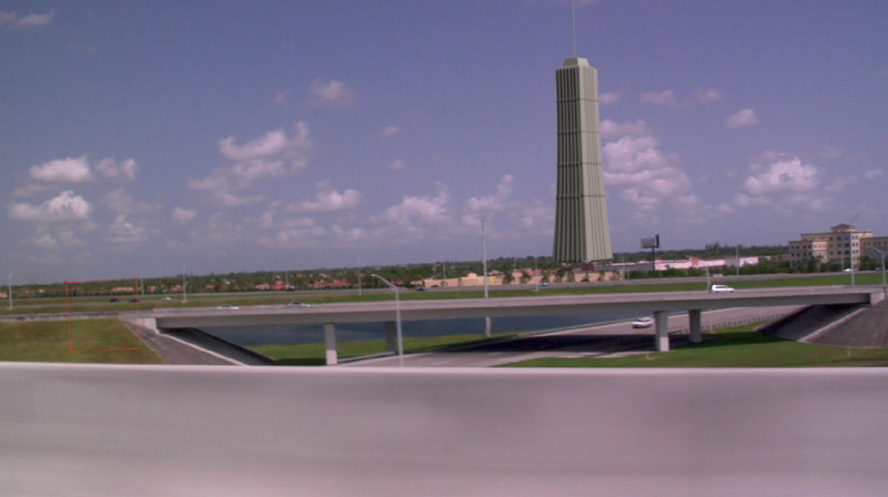
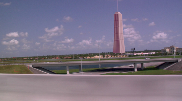
To illustrate this technique in a very bold way, we will 2D track and integrate a large 3D CG building into the background of seemingly common driving footage (shown in Figure 5.9), which was shot overlooking a city, from a moving car on a highway overpass. The footage was shot with a handheld camera and, as a result, is moving around quite a bit.
Figure 5.9. Moving footage shot from overpass
The creation of this type of VFX can be roughly distilled down to five basic steps.
Step 1: Analyze the Shot, Elements, and VFX to Be Created
Your first step—as always, when approaching a new VFX shot—is to carefully analyze the footage and determine what factors you are dealing with, the footage’s attributes, the lighting, and what you will need to do to create the desired effect.
Step 2: Light the Live Action Bluescreen/Greenscreen or 3D CG Element to Be Integrated
Using the methods and techniques for lighting elements covered in the previous section, we will open the building model in a 3D application and kill all the lights in the scene. As you can see from the footage/background plate, the main light source, the sun (using the two-clock description method covered in Chapter 1), is coming from approximately 5 o’clock (behind us) on a horizontal clock (where 12 o’clock is directly in front of us, 6 o’clock is directly behind us, 3 o’clock is 90 degrees to the right, and 9 o’clock is 90 degrees to the left), and about 2 o’clock on a vertical clock (where 12 o’clock is directly up, 6 o’clock is directly down, and so on). In the background image, you can see that it is a fairly bright day, so we want to make sure the intensity of the key light source is set to a match with a similar-in-appearance value (as shown in Figure 5.10).
Figure 5.10. 3D building lit with key light to match color and intensity of sunlight in the scene
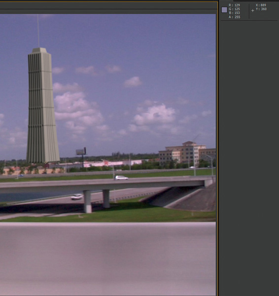
Once the key light is set, you can place and set your fill lights. You can set as few or as many as you’d like, but I highly recommend adopting the methodology of always using the fewest lights possible that get the job done. The fewer variables you have to contend with, the more control you have over the scene and, ultimately, the final results and output. At a bare minimum, in this scene you will need one fill light to emulate the bounce lighting from the sky (which will, of course, be blue-tinted) and one fill light to emulate the color of ground reflection or bounce (which in this case will reflect the colors of gray buildings, roads, green grass, greens and browns from trees, and so on). Using the eyedropper or color picker tool in Photoshop, you can get the exact value of the sky colors to ensure that your light color matches perfectly (see Figure 5.11).
Figure 5.11. Fill lights added to the 3D CG building model to match values in the background plate
Tip
Many artists (including your author) have a hereditary color deficiency. I have red/green color deficiency and know many artists with similar or other color deficiencies, or even just difficulty in color judgment. I rely on—and suggest all artists doublecheck color choices with—the color picker or eyedropper tool. These tools allow for the selection of a specific pixel color in a scene (in this case, the sky in the background plate) and to instantly get the exact values to plug in as a starting point for your light colors.
Though, many artists prefer to use distant or infinite lights to light their 3D scenes, and there is no definitive right or wrong when lighting, I prefer and recommend spotlights and point lights. Spotlights and point lights do require a little more work and tweaking due to their cone angles, radii, and falloffs, but ultimately, they allow the same kind of fine-tuned control that you want to have with real lights on a sound stage or in a studio—the ability to control your lights and prevent spill and contamination.
Step 3: Track the Live Action Background Plate
Because this footage is handheld and contains quite a bit of rocking and rotation, you’ll want to track both position and rotation (meaning a 2-point track will be required). Scrub the footage to get a general idea of the camera’s motion and to see how far the background elements travel from side to side throughout the duration of the clip. Doing so will help determine the best features to track—obviously, ones that don’t drift off screen. As you will remember from the 2D tracking guidelines covered in Chapter 2, you want to select high-contrast features that are on the same approximate Z plane (or approximately the same distance from camera). For this example, you will be integrating the CG building quite far into the distance. Place the first tracking point on a feature in the far distance on one side of the footage and the second tracking point the same approximate Z-depth from camera as far to the other side of the screen as possible. In Figure 5.12 you can see I’ve chosen clumps of trees on the horizon, which contrast nicely against the light sky.
Figure 5.12. Trackers set to track distant trees on either side of the background plate

Note
It is critical that you track areas of the footage in the same Z-depth as the depth of the element that you are going to integrate will appear. Although this is not always 100% possible, the nearer the better. The farther away from the Z-depth you track, the more drift and sliding your element will do, and the more hand adjustment and fixing you will have to do later.
Step 4: Composite and Matchmove Foreground Element over Live Action Background
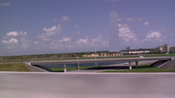
Once you have a solid track, import a still render of the lit 3D building with its alpha into your compositing application and do a simple composite of the foreground over the background, as shown in Figure 5.13. In a layer-based compositor like After Effects, this means simply placing the foreground layer above, or on top of, the background layer; in a nodal-based compositor like Nuke or Fusion, it means creating a simple merge node, piping the foreground into the “A” input and the background into the “B” input and setting the merge node to a simple “A over B.”
Figure 5.13. Simple A over B composite
Next you will apply the tracking data to the foreground image using whatever method your compositing application uses to apply tracking data. Depending on your compositing application, this may be done by using a pickwhip tool to parent the foreground element to the tracking data layer, or null (non-rendering helper object/layer), by copy and pasting the tracking data, or by using expressions (mathematical equations that allow variables, which can be used instead of specific input values). Once you have successfully applied your tracking data to the foreground element, it should be moving along with the footage nicely.
Note
Sometimes, when tracking data is applied, you will find that you might need to do a last-minute placement adjustment of your foreground image or that there are a few places where keyframes may slip and need to be corrected. By creating a new layer or merge and making it the parent of the one with the tracking data, you can, in essence, create an overriding “cheat” control, which you can use to make any fine-tune placement or keyframe animation adjustments.
Step 5: Fine-tune Color Correct (CC) and Finish Composite Adding Grading, Grain, Atmospherics, Artifacts, and More
Finally, once your CG element is locked into place, it’s time for the final integration tweaks. We’ll start with a handy procedural color-matching technique I’ve refined over the years for myself.
Note
Although being color-deficient or colorblind will require you to always doublecheck your color corrections with someone who has good color vision, this method will help you get “most of the way there” to an excellent color correction and match. This method has helped countless artists I’ve taught who previously thought they were incapable of achieving such great results.
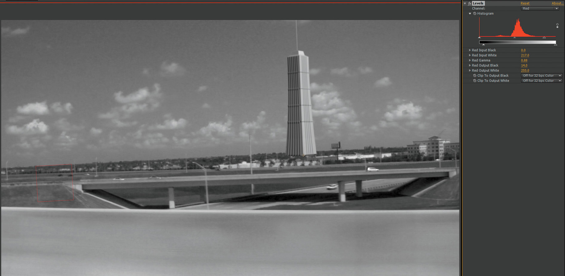
With the composite in the viewer and the foreground element selected, toggle on the color channel view to look only at the first color channel—in this case, the Red channel (see Figure 5.14). You should see a black and white grayscale image of the composite representing the Red channel. Notice that the foreground image doesn’t really look like it belongs in, or is part of, the background image. You will now apply a levels adjustment to the Red channel only and follow this procedure until it looks like it is integrated and actually a part of the background scene.
Figure 5.14. Red channel view of comp
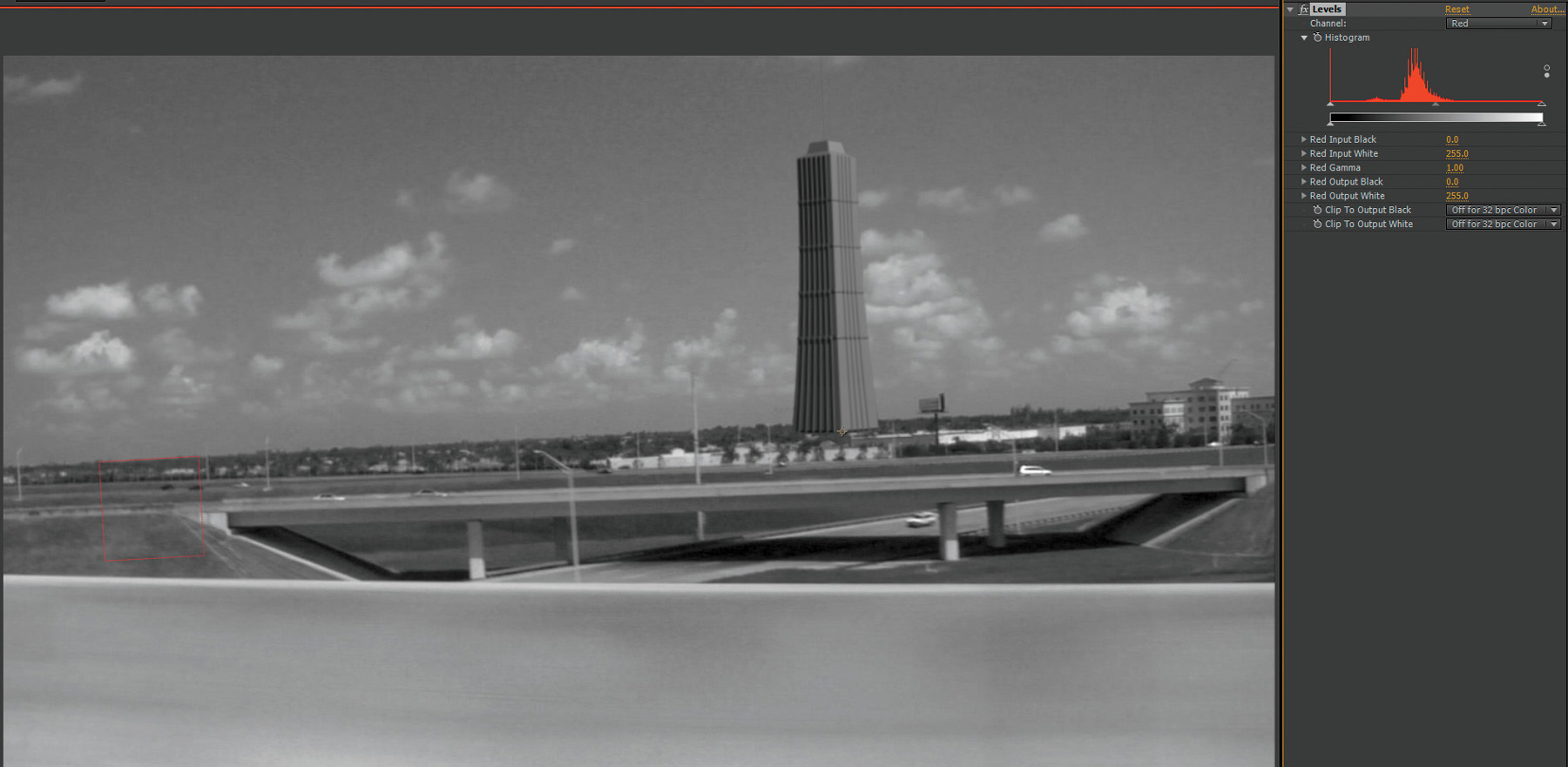
First, you want to match your black levels (or shadow density). Using the black input level control to darken the black levels or the black output level control to lift the black levels, match the darkest darks in your foreground image to the darkest darks in the background image. This might mean darkening them or brightening them (lifting the black levels), as shown in Figure 5.15.
Figure 5.15. Matching black/shadow densities
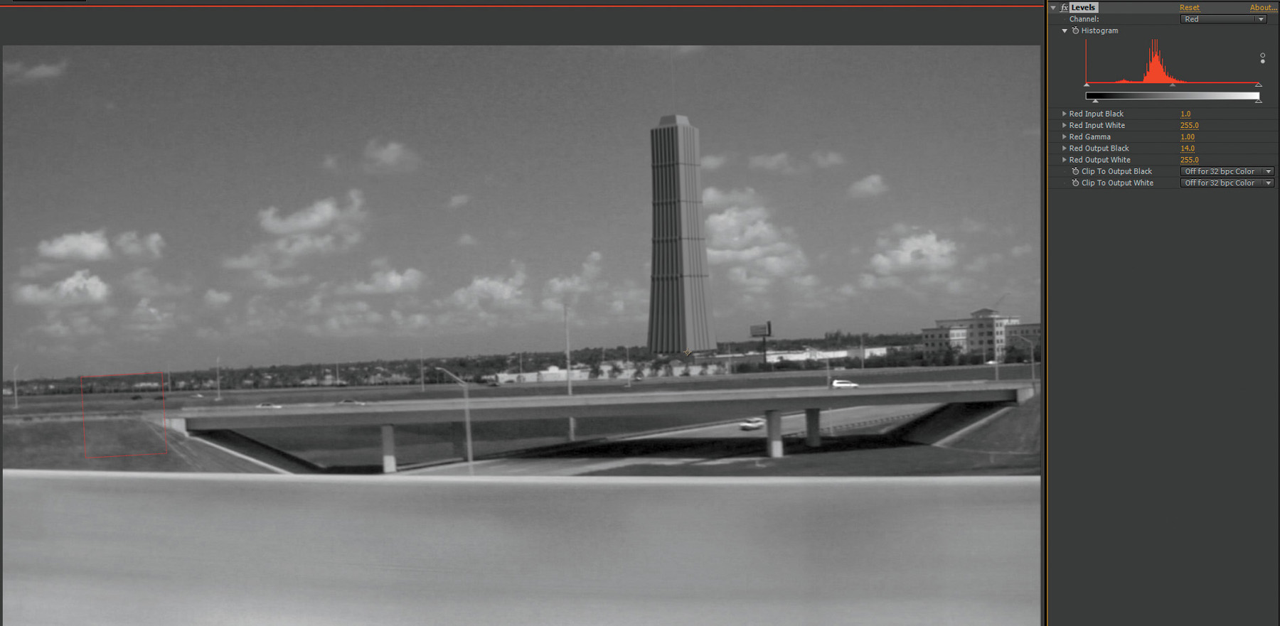
Next, do the same thing for the white levels (or highlights). Starting with the white level input control, brighten the whitest white levels in the foreground image to match the whitest whites in the background image. Or, using the white output control, darken the whitest whites to match the background’s whitest whites, as shown in Figure 5.16.
Figure 5.16. Matching white/highlight densities
After your black levels and white levels match, adjust your mid gray, or gamma, levels, using the middle gamma input control to match the overall mid gray level look of the image. Once the foreground image looks well integrated into the background plate, repeat the process individually with each of the Green and Blue channels, adjusting each with its own single color channel levels adjustment (as shown in Figure 5.17).
Figure 5.17. Matching gamma levels
Note
Be very careful not to accidentally do a 3-channel (overall) levels adjustment to each of the channels, -- that would likely cause a giant mess. Luckily, these adjustments are all non-destructive and will not cause any undoable damage if done incorrectly.
Once the individual channel levels adjustments are completed, an overall RGB levels or curves adjustment can be done to further refine the integration.
Tip
Be very careful with the black and white output controls. You will find that if you are having to push either of these more than about 10–20% (as in Figure 5.18), your color will quickly go way out of whack. If you find that you need to push them more, try resetting these and using the gamma control instead.
Figure 5.18. Black output and white output controls pushed too far will create very bad color issues.
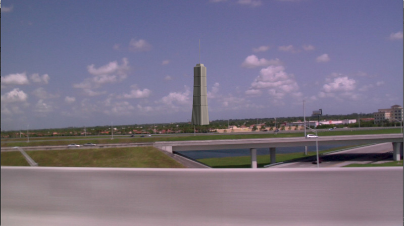
After your colors and densities are all matched (see Figure 5.19), you can add one more level of integration detail by adding in a layer of atmosphere, or aerial perspective. To do this, you can simply use the color picker or eyedropper tool to select a color in the atmosphere at the horizon or closest to where your CG element will be placed in the scene (see Figure 5.20).
Figure 5.19. Matched density/color levels

Figure 5.20. Color picker used to select atmosphere color
Then add a solid layer, or constant, using this color and apply the alpha of the 3D or keyed element to have it affect only this element (see Figure 5.21).
Figure 5.21. Atmosphere color layer using alpha to cut out and apply only to the CG building
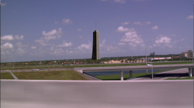
Finally, adjust this layer’s opacity until the underlying CG element appears to take on the correct amount of atmosphere and blend perfectly into the scene (Figure 5.22).
Figure 5.22. Atmosphere/aerial perspective layer’s opacity adjusted to match distance

Congratulations! You have successfully completed your first CG integration VFX.
Roto VFX: Energy Weapons and Effects
In this section, you will tackle two techniques at once: the creation of a roto-based VFX and the creation of an energy weapon VFX. Roto-based VFX are any effect that uses rotosplining or frame-by-frame animating as the main tools to create the effect. This can include anything from light saber effects (similar to what we are doing here) to digital amputations and wire and rig removals. Energy weapon effects include a wide range of effects but are mainly focused on those that appear to be created by high concentrations of energy: electricity, plasma, explosives, lasers, and so on. These types of VFX are very important to VFX artists because, well, creating dangerous-looking effects that will be placed in very close proximity to highly paid actors is a great deal of what we do. These effects are also critical to understand because knowing the structure of such weapons and the principles and techniques used to re-create them gives you the knowledge to tackle almost any energy-based effect (because in the real world they all respond photographically in a similar manner and have similar visual components and structure). We’ll begin by examining the components of an energy weapon.
Components of an Energy Weapon or Effect
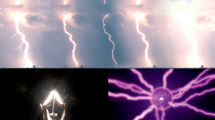
At the heart of every powerful energy weapon or discharge is its core, or source. As discussed in Chapter 1, when you create VFX, you’re not always necessarily creating an exact replica of reality. More often than not, you’re re-creating what a camera would see if it were filming the effect. In the case of a high energy source or weapon, the limitations in latitude of photographic film and video sensors would likely cause the core of that energy source to blow out or clip the upper limits of the recording medium’s ability. This would result in what would look like a pure white, RGB 255, 255, 255 origin that would take on the vague shape of whatever was producing it. In the case of a light saber, it would be a long, straight, sword-like core; on a ball of plasma, a sphere; and in the case of lightning, the familiar treelike branching. Because the energy produced from this type of weapon or discharge is so great and in flux (moving), it will usually appear as a glowing, soft-edged structure and will not be perfectly well defined (unless it is to be contained within some kind of structure).
Emanating outward from the core will be a hot, glowing area of highly charged or heated air. This is the area that begins to take on the energy’s color characteristics, if it has any. And dissipating outward from this area will be the falloff area—the region where the charged particles, or air, taper off and return back to normal. You can see examples of these in Figure 5.23.
Figure 5.23. Examples of high-energy discharges
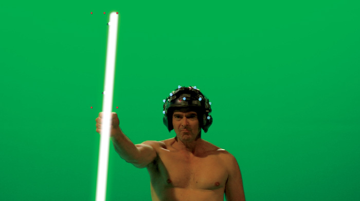
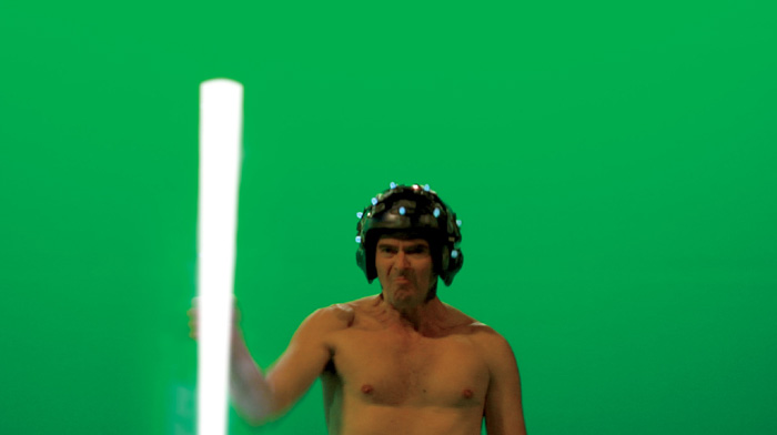
This example uses footage of actor Steve Roth, shown in Figure 5.24, portraying the sun god Ra. The footage was shot with helmet- and staff-tracking markers in front of a greenscreen.
Figure 5.24. Greenscreen footage of actor Steve Roth with tracking-markered helmet and staff
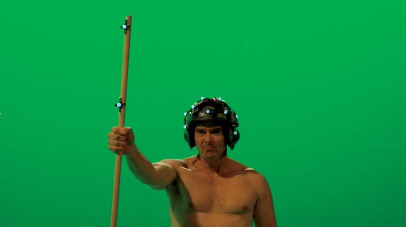
For this example, we will create Ra’s energy staff. Later, in Chapter 7, we’ll add Ra’s headpiece when we cover 3D object tracking and replacement.
Because the staff is a solid object and doesn’t change shape, in this case, we can get away with using only one simple rotoshape for the core. Start by creating a rotoshape for the staff (using the roto guidelines covered in Chapter 3), as shown in Figure 5.25.
Figure 5.25. Rotoshape of staff
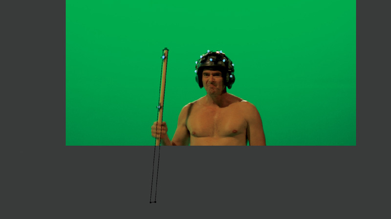
Because you will cover the entire shape with the energy weapon effect, you can save yourself some work by completely encompassing the staff within the rotoshape. Keyframe the shape to animate along with the character’s motion (see Figure 5.26), following the technique and guidelines in Chapter 2.
Figure 5.26. Rotoshape keyframed

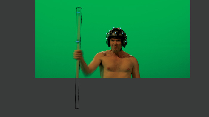
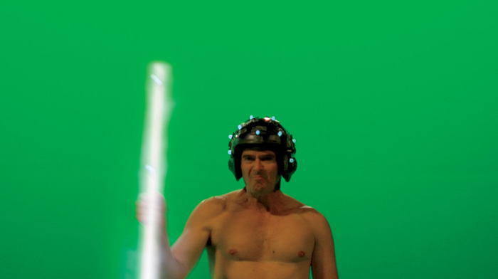
For those few frames where there is significant motion blur, it is okay in this case to animate the entire shape of the rotospline to widen, for those few frames, to encompass the entire blurred shape, as shown in Figure 5.27.
Figure 5.27. Rotoshape widened to cover motion blur
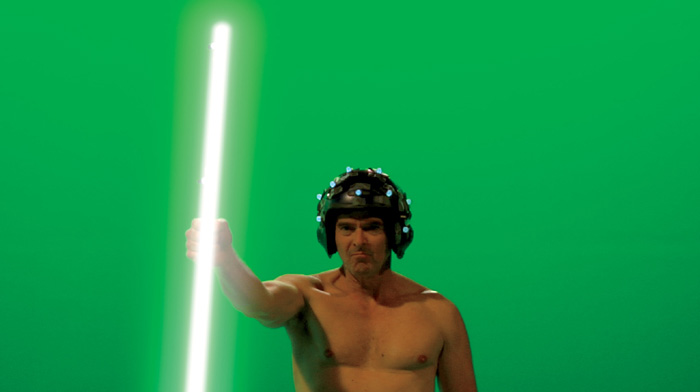
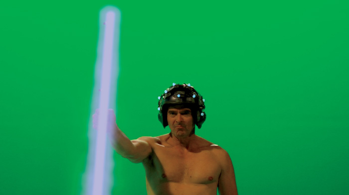
Use this rotoshape on a solid white layer or constant to create an animated core, as shown in Figure 5.28.
Figure 5.28. White solid/constant used to create core

Because this will no doubt be too sharp, feather the edges of the rotoshape outward, as shown in Figure 5.29. You may need to expand or dilate the shape slightly to maintain complete coverage of the stand-in staff.
Figure 5.29. Rotoshape feathered and dilated slightly to soften and widen energy core

It is also perfectly valid to use a blur on the shape instead of using an edge feather. Our guiding rule and principle in VFX applies here: “If it looks right, it’s right.”
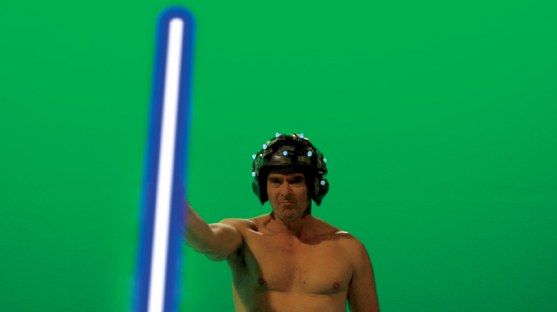
After your core is complete, duplicate this shape (or layer), place it behind (or under) the core layer, expand or dilate it outward slightly, and then lower this layer’s opacity. This layer will be used to create your energy weapon’s glow, as shown in Figure 5.30. (You may need to further feather this layer’s edges as well.)
Figure 5.30. Duplicated layer expanded and made more transparent for glow
Next, duplicate the glow layer (placing it under or behind both previous layers) and repeat the process of expanding, feathering it slightly, and again lowering the opacity. You will use this to create the energy weapon’s glow falloff, as shown in Figure 5.31.
Figure 5.31. Glow falloff added
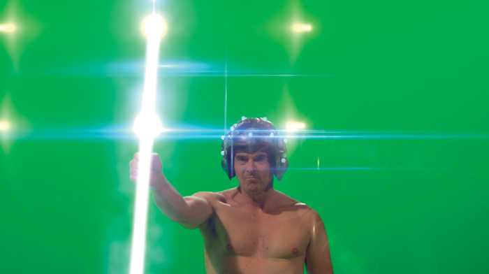
Once you have this base energy weapon set up, you can add slight animated noise or displacements to each of the layers and/or their alphas to create pulsing effects, and slight color corrections to the glow layers to create color variations, as shown in Figure 5.32. You can add other glow, filter, and lens flare effects to this effect framework as well for finishing touches (see Figure 5.33). In Chapter 13 we will also learn to add fake interactive lighting to the character in this type of effect (which we would naturally expect to occur from the light being emitted from such a weapon).
Figure 5.32. Pulse and color effects added
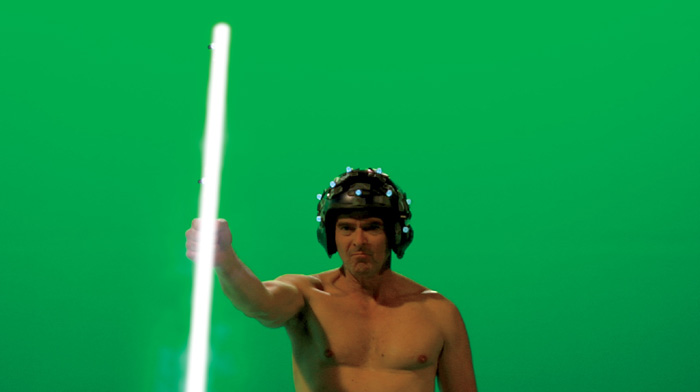
Figure 5.33. Glow and lens flare finishes
And that’s all there is to it. You can create almost any type of imaginable energy effect using this layering (core, glow, falloff) methodology—from suns, lasers, and plasma to photon torpedoes, light sabers, and lightning!
Tips and Tricks for Energy VFX
Here are some tips and tricks to keep in mind and follow when creating energy-based weapons and effects. You want to avoid the common pitfalls that often ruin the results of beginning VFX artists creating these types of effects.
• When creating roto-based energy weapons and trying to follow stand-in objects that move quickly, there are two basic philosophies/methods as to how to approach and address dealing with motion blur. Neither is necessarily right or wrong; it all depends on the effect you are trying to achieve and how much time you have to achieve it.
The first method is to ignore the motion blur and cover the entire area with a solid roto shape. This is the easiest and most painless way to go and gives a look very similar to that of the light sabers in the original Star Wars movies (see Figure 5.34).
Figure 5.34. Solid rotoshape covering motion blur
The second method is, perhaps, more technically accurate but much more difficult to control and get perfect results from In this method you create a roto shape of the original stand-in object and then try to match the motion blur using motion blur control, shutter frame, and bias settings (see Figure 5.35).
Figure 5.35. Motion blur added and adjusted to rotoshape
• The core of an energy weapon is hot and thus emanates brilliant light. Color from falloff areas cannot appear in front of this light (as in Figure 5.36) because it is less brilliant. Core energy should always be the topmost layer or effect, with falloff light or color emanating from behind the source. You will almost always want to use Add or Screen blend modes for these types of effects.
Figure 5.36. Incorrect placement of color falloff on top of hot core effect
• Energy by its nature is moving and, like everything else in nature, not sharp or perfect edged. Energy weapons and effects should always have slightly feathered, natural glowing edges (though not too feathered). Adding slight noise or motion to the shapes of the core and outer layers will also add naturalistic effects.
• High-energy discharges are usually caught by photographic recording mediums as pure white, fading off to a color. When adding color to your energy weapons and effects, keep colors subtle and at the outer glow areas of the effects. Do not use candy-like saturated colors (as in Figure 3.37) and definitely do not color the core (unless you are specifically required to do so).
Figure 5.37. Coloration too saturated
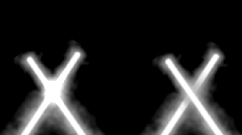
• When two energy sources overlap or collide (in the case of light sabers, crossing electrical branches, or overlapping fire or explosions), they are light sources and additive, meaning they combine to form white. They cannot shadow one another, and the glow of the frontmost source will combine and disappear into the core and glow of the rearmost effect. Correct and incorrect are shown in Figure 5.38.
Figure 5.38. Correct (left) and incorrect (right) energy effect
• When two high-energy sources meet, they tend to arc or flash. Again, in a real photographic situation this would tend to completely overwhelm the photographic response and latitude of the recording medium, resulting in a completely blown out (or clipped to white) frame. You can use this phenomenon to your advantage to create seemingly super-powerful weapons and effects by creating lens flare elements at the point of crossing and then by simply placing a full white frame or two at the frame of impact. The result makes viewers feel that the impact was so intense it blew out the frame and overwhelmed the camera! Clever, huh?
Basic 2.5D VFX
There are times in VFX when creating an entire 3D scene is just too time and resource consuming. There are also those times when a 2D scene or composite just isn’t enough. No discussion of VFX would be complete without exploring one of the VFX world’s best kept and most closely guarded secrets ... that mystical realm known as two and a half D (2.5D)!
Basic 2.5D VFX
2.5D truly captures the essence of VFX’s “do whatever you have to do to get it done” spirit and comes in many forms, configurations, shapes, and flavors. In its most basic definition, 2.5D is any combination of 2D and 3D that isn’t purely one or the other.
This could mean 2D layers stacked and spaced out in 3D space to allow parallax between the flat layers or a 3D scene with 2D cards instead of 3D geometry. Or it could mean 2D planes extruded into 3D to allow just enough parallax to pull off a 3D conversion. More often than not, it’s some combination of any or all of these. 2.5D is the epitome of guerrilla production creativity, ingenuity, and resourcefulness and is a shining example of the filmmaking spirit.
2.5D is covered in many aspects and great detail in Chapters 6, 8, 10, 13, 14, and 15, but let’s take a quick look at a few different, clever ways you can use 2.5D to create fake shadow and reflection effects.
2.5D Fake Shadows & Reflections
When you create VFX such as energy weapons, it’s easy to overlook small details that are needed to make your results look realistic. When you create a light saber, for example, you also need to create the effect of the interactive light that this weapon emits. It’s even easier to overlook the shadows and reflections that this interactive light would create as well.
Chapter 1 discussed the components of a shadow, which are important to VFX artists. The structure of shadows is very similar to the structure of the light of an energy weapon, only somewhat in reverse: contact, core or umbra, and falloff or penumbra. Creating fake shadows and reflections are vital skills you will need as a VFX artist. Let’s take a look at two completely different methods to use 2.5D to create fake shadows and reflections. The first we’ll call the 2.5D Card Method, and the second we’ll call the 2.5D Projection Method.
2.5D Card Method of Creating Fake Shadows and Reflections
The advantage that creating 2.5D fake shadows and reflections has over just plain 2D fake shadows and reflections is that, using 2.5D, you can actually create realistic perspective. Shadows and reflections falling on an actual wall or ground plane and take on the more realistic foreshortening and falloff appearance that a simple 2D distortion cannot easily provide.
To create a simple fake 2.5D shadow or reflection, follow these steps:
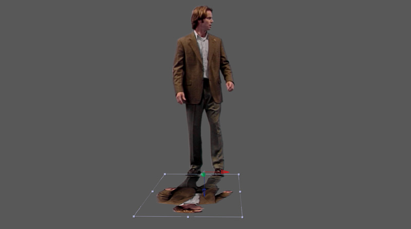
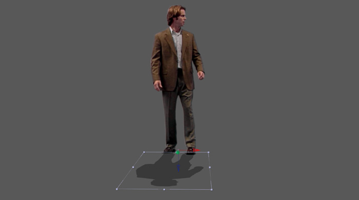
1. Create a 2D plane in 3D space and apply a copy of the shadow or reflection’s source image and alpha. This should give you a duplicate of your subject (in this case, our actor extracted from a bluescreen), as shown in Figure 5.39.

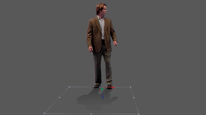
2. Move the pivot point of the 2D plane/card to the very bottom and then rotate the card 90 degrees on the X axis until it is laying down in the desired position, as shown in Figure 5.40.
Figure 5.40. Pivot point moved and card rotated 90 degrees on X axis
Note
For a reflection, you could simply lower the opacity, apply a blend mode, and add masks, displacements, and/or imperfections to add realism, but a shadow requires a few more steps.
3. Apply a hue/saturation to the shadow object and remove all saturation, as shown in Figure 5.41.
Figure 5.41. Image desaturated
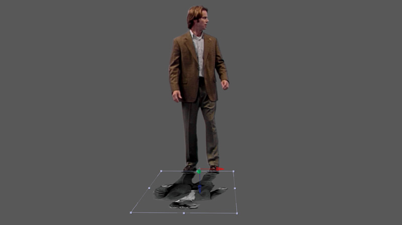
4. Next, lower the brightness all the way to 0 to create a completely black shadow, as shown in Figure 5.42.
Figure 5.42. Brightness lowered to black
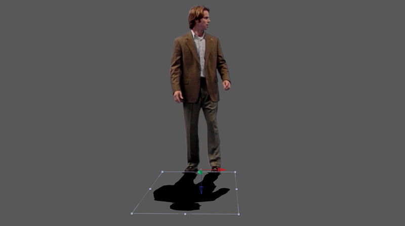
5. Set the blend mode to multiply and lower the opacity until it matches the density of surrounding shadows in the scene, as shown in Figure 5.43.
Figure 5.43. Blend mode set to multiply and opacity lowered
6. Finish the shadow by applying blur (or a gradient mask with blur) to create a fake, but realistic falloff, as shown in Figure 5.44.
Figure 5.44. Blur added to create falloff
2.5D Projection Method of Creating Fake Shadows and Reflections
Whereas the previous method uses a 2D plane to simulate the look of a shadow with the shadow basically pasted on it, the effect falls apart if the shadow has to fall upon any uneven geometry, such as angular walls or stairs. For such a situation, you can use a slightly more sophisticated method and setup to actually project a shadow onto the desired geometry.
To begin, follow these steps:
1. Repeat steps 1-4 of the previous section to create a black silhouette of the shadow to be projected. This will be your shadow caster (shown in Figure 5.45).
Figure 5.45. Silhouetted black shadow caster

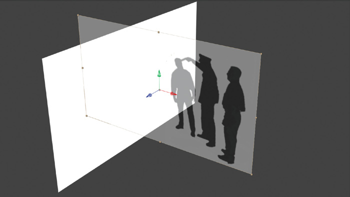
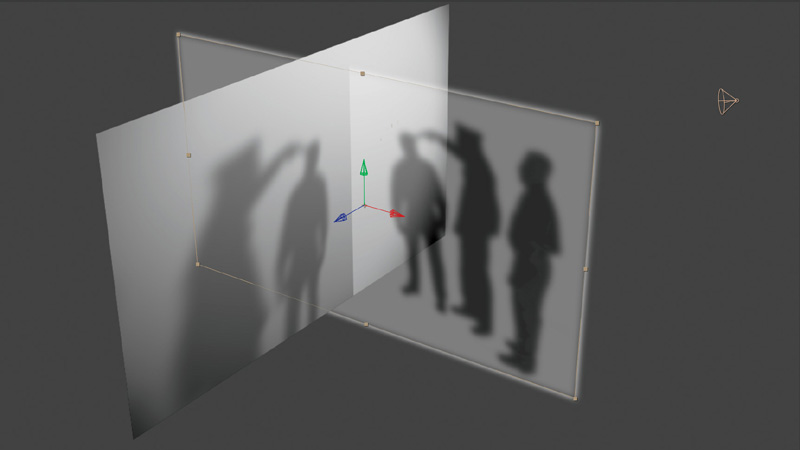
2. Create stand-in geometry using 2D cards or basic 3D geometry for any areas of the background image scene that you’d like shadows to fall upon. Align these with the image and set their material and color to all white. These cards or objects (shown in Figure 5.46) will be our shadow catchers.
Figure 5.46. Shadow catcher objects
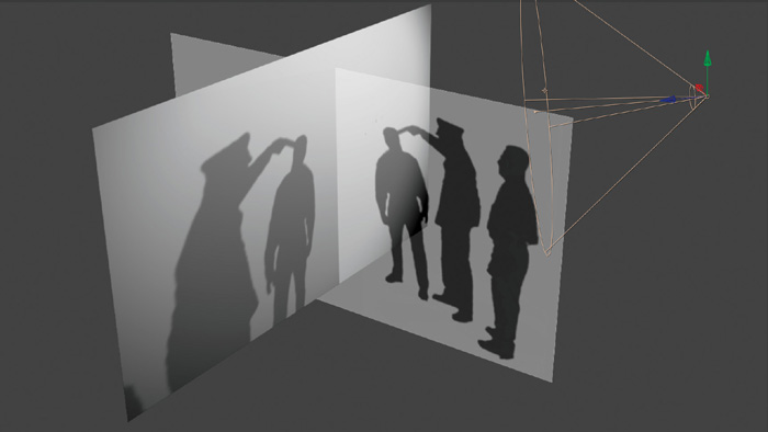
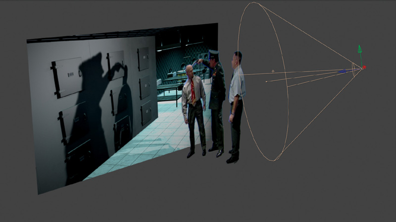
3. Create a spotlight in your scene like the one shown in Figure 5.47 and position it to project its light to cast a shadow from the silhouette card onto the stand-in geometry.
Figure 5.47. Spotlight added and positioned to cast shadow

4. Set the spotlight to raytrace or cast shadows and the stand-in objects and materials to receive shadows (see Figure 5.48).
Figure 5.48. Materials set to receive shadows
5. Set the shadow caster’s object/material properties to cast shadows, seen by rays but set to unseen by camera. This will allow the object to cast shadows, using the alpha of the actual motion footage, onto the shadow catcher objects, yet not be seen itself in the scene, as shown in Figure 5.49).
Figure 5.49. Shadow caster set to cast shadow but to be unseen by camera
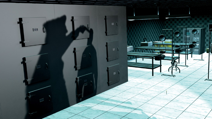
6. As in step 5 of the previous section, setting the shadow catcher planes/objects blend mode to multiply and then lowering the opacity allows the shadows to blend nicely and naturally onto the contours of the underlying geometry and to appear to actually be in the scene, as shown in Figure 5.50.
Figure 5.50. 2.5D shadows appear to be casting onto image properly
7. Also as in the previous section, blurs can be applied to soften the shadows to match the background plate (see Figure 5.51).
Figure 5.51. Fine-tune blur added to soften shadows
Now that you’ve done a simple integration, in Chapter 6, we’ll dive into some more sophisticated VFX and learn some more advanced techniques to further fine-tune your composites and integrations.