
Day 6. IDS/IPS Concepts
CCNA Security 210-260 IINS Exam Topics
![]() 6.1.a Network-based IPS vs. host-based IPS
6.1.a Network-based IPS vs. host-based IPS
![]() 6.1.b Modes of deployment (inline, promiscuous - SPAN, tap)
6.1.b Modes of deployment (inline, promiscuous - SPAN, tap)
![]() 6.1.c Placement (positioning of the IPS within the network)
6.1.c Placement (positioning of the IPS within the network)
![]() 6.1.d False positives, false negatives, true positives, true negatives
6.1.d False positives, false negatives, true positives, true negatives
Key Topics
Today we will review the concepts behind intrusion detection and protection. We will look at the difference between an intrusion detection system (IDS) and an intrusion prevention system (IPS), as well as compare a network-based IPS and a host-based IPS. We will also discuss the different network deployments options available for IPS sensors. Finally, we will define some of the common terminology related to IPS technologies.
IDS vs. IPS
Intrusion detection/prevention sensors are systems that detect activity that can compromise the confidentiality, integrity, and availability of information resources, processing, or systems. Intrusions can come in many forms. Various technologies have been developed to detect intrusions. The first technology that was developed, IDS, had sensing capabilities but little capability to take action upon what it detected. Traditionally, IDSs were implemented to passively monitor the traffic on a network. An IDS-enabled sensor receives copies of the traffic stream and analyzes this traffic rather than the actual forwarded packets. Working offline, it compares the captured traffic stream with known malicious signatures, similar to software that checks for viruses. Although the traffic is monitored and perhaps reported, no action is taken on packets by the IDS. This offline IDS implementation is referred to as promiscuous or passive mode.
An IPS works inline in the data stream to provide protection from malicious attacks in real time. This is called inline mode. Unlike an IDS, an IPS does not allow packets to enter the trusted side of the network if they are anomalous. An IPS has the ability to analyze traffic from the data link layer to the application layer. For example, an IPS can
![]() Analyze the traffic that controls Layer 2 to Layer 3 mappings, such as ARP and DHCP
Analyze the traffic that controls Layer 2 to Layer 3 mappings, such as ARP and DHCP
![]() Verify that the rules of networking protocols such as IP, TCP, UDP, and ICMP are followed
Verify that the rules of networking protocols such as IP, TCP, UDP, and ICMP are followed
![]() Analyze the payload of application traffic to identify things such as network attacks, the presence of malware, and server misconfigurations
Analyze the payload of application traffic to identify things such as network attacks, the presence of malware, and server misconfigurations
Figure 6-1 shows a sensor deployed in IDS mode and a sensor deployed in IPS mode.
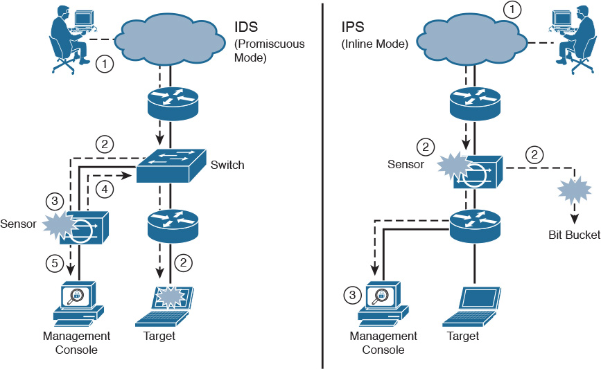
The following are the steps that occur when an attack is launched in an environment monitored by an IDS:
1. An attack is launched on a network that has a sensor deployed in IDS mode.
2. The switch sends copies of all packets to the IDS sensor (configured in promiscuous mode, which is explained later in this section) to analyze the packets. At the same time, the target machine experiences the malicious attack.
3. The IDS sensor, using a signature, matches the malicious traffic to the signature.
4. The IDS sensor sends to the switch a command to deny access to the malicious traffic.
5. The IDS sends an alarm to a management console for logging and other management purposes.
The following are the steps that occur when an attack is launched in an environment monitored by an IPS:
1. An attack is launched on a network that has a sensor deployed in IPS mode (configured in inline mode, which is explained later in this section).
2. The IPS sensor analyzes the packets as soon as they come into the IPS sensor interface. The IPS sensor, using signatures, matches the malicious traffic to the signature and the attack is stopped immediately. Traffic in violation of policy can be dropped by an IPS sensor.
3. The IPS sensor can send an alarm to a management console for logging and other management purposes.
Note
The term management console, as seen in Figure 6-1, refers to a separate workstation equipped with software to configure, monitor, and report on events. We will discuss this type of software on Day 5.
Figure 6-2 shows a common IPS deployment, in which the Cisco ASA controls access between the corporate network and the Internet, based on source and destination IP addresses and ports, while the FirePOWER IPS appliance controls access based on packet payload.

IPS technology is deployed in a sensor, which can be described as one of the following:
![]() An appliance that is specifically designed to provide dedicated IPS services (as seen in Figure 6-2).
An appliance that is specifically designed to provide dedicated IPS services (as seen in Figure 6-2).
![]() A module that is installed in another network device, such as an ASA, a switch, or a router. The ASA 5506-X with FirePOWER is an example of this type of deployment.
A module that is installed in another network device, such as an ASA, a switch, or a router. The ASA 5506-X with FirePOWER is an example of this type of deployment.
When intrusion detection technology was first conceived, two fundamentally different strategies were used:
![]() Anomaly detection: This type of technology generally learns patterns of normal network activity and, over time, produces a baseline profile for a given network. Sensors detect suspicious activity by evaluating patterns of activity that deviate from this baseline.
Anomaly detection: This type of technology generally learns patterns of normal network activity and, over time, produces a baseline profile for a given network. Sensors detect suspicious activity by evaluating patterns of activity that deviate from this baseline.
![]() Rule-based detection: Attackers use various techniques to invade and compromise systems. Many techniques are directed at known weaknesses in operating systems, applications, or protocols. Various remote surveillance techniques are also frequently used. Some surveillance and attack methods have known patterns by which the method can be identified. Malicious activity detectors typically analyze live network traffic using a database of rules to determine whether suspicious activity is occurring.
Rule-based detection: Attackers use various techniques to invade and compromise systems. Many techniques are directed at known weaknesses in operating systems, applications, or protocols. Various remote surveillance techniques are also frequently used. Some surveillance and attack methods have known patterns by which the method can be identified. Malicious activity detectors typically analyze live network traffic using a database of rules to determine whether suspicious activity is occurring.
Modern IPS systems combine anomaly detection and rule-based detection, as well as other newer and sophisticated technologies such as reputation, context awareness, event correlation, and cloud-based services to ensure network protection.
Host-based vs. Network-based IPS
There are two types of IPS: network-based IPS and host-based IPS. Traditionally, a host-based IPS relied on agents that were placed on crucial systems in the enterprise. The agents monitored various aspects of the host operation for signs of suspicious activity. The agents would report detections to a central management console or write event activity to system logs.
A more modern approach is to position the IPS processing in the cloud and place a lightweight connector on the host to access the cloud-based protection. This architecture scales much more effectively, allowing the protection of all systems on the network.
A host-based IPS can detect intrusions that utilize encrypted communications. A network-based IPS does not normally have visibility into encrypted traffic streams, but a host-based IPS can analyze activities within the host operating system after traffic is received and decrypted and before traffic is sent and encrypted. A host-based IPS is well suited for detection of activity that does not generate network traffic. For example, a host-based IPS is likely to detect activity such as policy violations or physical compromise of the system, such as when unauthorized users attempt local access. A host-based IPS can easily detect changes in the integrity of crucial files by comparing file hashes to known-good hash profiles.
A host-based IPS has some disadvantages, however. For example, it requires agents to be installed on every machine that needs to be monitored. As such, remote management of these agents can be a challenge. Also, system administrators might be concerned with placing an additional processing burden on heavily utilized systems or simpler mobile devices. Finally, certain host-based IPS agents can present the user with pop-up messages, forcing the user to actively interact with the client software. This could detract from the overall user experience, resulting in users either disabling the agent (if they have the administrative rights) or calling technical support.
IPS Deployment Options
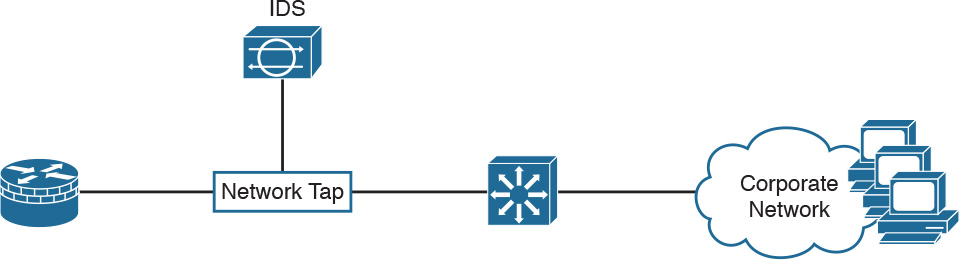
There are several options for deploying a network sensor in promiscuous or passive mode. One of the most common methods is to configure the Switched Port Analyzer (SPAN) feature on a Cisco Catalyst switch and connect the IPS sensor to the SPAN destination port. The IPS sensor will then see copies of all frames that match the SPAN capture configuration, as shown in the IDS scenario in Figure 6-1. One limitation of a SPAN solution is that the SPAN destination port may become oversubscribed. A solution is to use a network tap. A network tap is inserted directly between two devices. It provides full-duplex connectivity between the two devices, and allows the IDS to literally tap into the traffic flow. Figure 6-3 shows where a network tap would be deployed.
There are many different options for deploying sensors inline. If the traffic must traverse the sensor in the data forwarding path, the deployment is considered to be inline. For example, the sensor can be placed between a router and a switch, or between a pair of routers, or between a pair of switches. Traffic that travels between the two devices must traverse the sensor, as depicted in the IPS scenario in Figure 6-1.
The sensor can also be deployed as a software module in an ASA. Although the module is embedded within the ASA, the module is a separate entity with its own operating system and configuration. A policy can be configured to send traffic traversing the ASA to the FirePOWER module for deep IPS services. If the policy is configured with the monitor-only option, traffic is mirrored to the module for IPS services but the module is not in the forwarding path. On the other hand, if the monitor-only option is not specified, the module is in the forwarding path. The ASA forwards packets to the module, where the module may drop malicious traffic itself, preventing it from being forwarded by the ASA.
The policy on the ASA can also be configured to be fail-open or fail-closed. This setting determines what the ASA does with traffic that it is configured to send to the FirePOWER module when the module itself is down. With fail-open, the ASA continues to process the traffic itself and can still forward the traffic toward its destination. With fail-closed, the ASA drops the traffic that it is configured to send to the FirePOWER module. Fail-closed is configured in situations where network security is more important than network availability.
IPS Placement
An argument can be made for the use of IPS at any position in a network, but deploying IPS everywhere in the network is not feasible. Placement decisions must be made, and each scenario will have different requirements that influence the decisions. Figure 6-4 shows a network with three security zones: inside, outside, and DMZ. A sensor could be placed inline between the firewall and any of the zones.

Consider the following information about this scenario to help determine where to place a sensor within your network:
![]() Outside: At first impression, the outside network may seem to be the best location for the sensor. The scariest threats are on the Internet, so it could seem reasonable to use the IPS to protect the network from the Internet. However, the ASA security appliance will provide substantial threat protection from the Internet. Furthermore, with the sensor on the outside network, the number of alarms will be high, and the alarms can be considered false positives if the ASA security appliance would have provided protection anyway.
Outside: At first impression, the outside network may seem to be the best location for the sensor. The scariest threats are on the Internet, so it could seem reasonable to use the IPS to protect the network from the Internet. However, the ASA security appliance will provide substantial threat protection from the Internet. Furthermore, with the sensor on the outside network, the number of alarms will be high, and the alarms can be considered false positives if the ASA security appliance would have provided protection anyway.
![]() DMZ: DMZ servers have services that are exposed directly to the Internet. Any vulnerabilities in the service applications or configurations can be exploited. Certainly, IPS can play a security role on the DMZ. However, the data that is stored on DMZ systems is likely to be much less critical than data stored on internal servers. Because these systems are hardened by and managed by IT professionals, the likelihood of exposed vulnerabilities should be relatively low, and compromised systems should be recognized relatively quickly.
DMZ: DMZ servers have services that are exposed directly to the Internet. Any vulnerabilities in the service applications or configurations can be exploited. Certainly, IPS can play a security role on the DMZ. However, the data that is stored on DMZ systems is likely to be much less critical than data stored on internal servers. Because these systems are hardened by and managed by IT professionals, the likelihood of exposed vulnerabilities should be relatively low, and compromised systems should be recognized relatively quickly.
![]() Inside: The inside systems are best protected by the firewall, but they are typically run by users who lack experience in IT or information security. Users may unintentionally bring malware into the internal network, where the most critical and confidential data is stored. A compromised client PC is likely to have access to confidential information stored on internal servers. If you can place an IPS sensor in only one place, placing the sensor just inside the firewall may be the best option.
Inside: The inside systems are best protected by the firewall, but they are typically run by users who lack experience in IT or information security. Users may unintentionally bring malware into the internal network, where the most critical and confidential data is stored. A compromised client PC is likely to have access to confidential information stored on internal servers. If you can place an IPS sensor in only one place, placing the sensor just inside the firewall may be the best option.
IPS Terminology
When deployed in real environments, security controls such as IPS may produce erroneous decisions, either because of their misconfiguration or because of the environment, in which legitimate activity may resemble malicious activity, and vice versa.
All decisions made by security controls can be classified as one of the following:
![]() True positive: The security control, such as an IPS sensor, acted as a consequence of malicious activity. This represents normal and optimal operation.
True positive: The security control, such as an IPS sensor, acted as a consequence of malicious activity. This represents normal and optimal operation.
![]() True negative: The security control has not acted, because there was no malicious activity. This represents normal and optimal operation.
True negative: The security control has not acted, because there was no malicious activity. This represents normal and optimal operation.
![]() False positive: The security control acted as a consequence of normal traffic or activity.
False positive: The security control acted as a consequence of normal traffic or activity.
![]() False negative: The security control has not acted, even though there was malicious activity.
False negative: The security control has not acted, even though there was malicious activity.
Positive or negative refers to whether the alarm was triggered. Positive designates an alarm has been triggered, and negative designates an alarm has not been triggered. True or false is more complex; this answers the question, “Was the result to trigger (or not trigger) the alarm the right decision?” If the action taken by the sensor was right, then the result is true, and if the sensor took the wrong decision, the result is false.

Refer to the Digital Study Guide to view this video.
 Activity: Match the IDS and IPS Terminology to Its Definition
Refer to the Digital Study Guide to complete this activity.
Study Resources
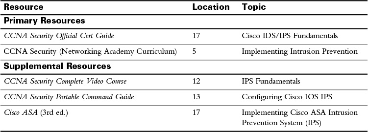
For today’s exam topics, refer to the following resources for more study.
![]() Check Your Understanding
Check Your Understanding
Refer to the Digital Study Guide to take a ten-question quiz covering the content of this day.