Simple machines are devices that change the amount, or magnitude, of force or the direction of a force being exerted on something. The standard list of simple machines (at least as far as school science standards define them) are the pulley, screw, wheel and axle, inclined plane, wedge, and lever. Most of these are very old—the wheel’s origin is lost in antiquity, Archimedes knew about the lever, screw, and pulley about 2,300 years ago, and the rest were used to build the pyramids (but not included in Archimedes’s list of machines).
The physics behind simple machines, though, was not clarified in some cases till the late 1700s. There is a good history of these technologies on the Wikipedia page https://en.wikipedia.org/wiki/Simple_machine. The force-lessening effect that these machines exploit is called mechanical advantage. Often it is manifested by moving an object over a distance more slowly but with less force than one would without the intervention of a machine—for example, pushing something up a ramp (inclined plane) versus lifting it straight up.
Physics Background
Most of the things we normally think of as machines are combinations of these basic simple machines. Using more than one simple machine creates a compound machine. For example, a wheelbarrow is a combination of a lever (the handle) and two wheels on an axle (at least, for the version we show in a later figure).
Typically simple machine discussions focus on unpowered machines—ones that rely on human (or animal) power that is then converted into mechanical energy of some sort, with or without amplification, based on the geometries of the machine.
In this chapter, we have created basic versions of the six simple machines in OpenSCAD with the intent that you can 3D print them individually to use as demonstrations. The OpenSCAD model for each is designed so that you can vary critical dimensions to build intuition about how the effects of each machine changes as a result.
Each machine may have some particular caveats about scaling, which we talk about as we introduce them. You will also want to experiment with combining simple machines into compound ones. We give one example of a combination after we introduce all six machines.
Friction and flexing of the machine lower their efficiency to a greater or lesser degree, and you should bear that in mind if your experiments do not achieve the mechanical advantage that your calculations might indicate.
The Machines
We developed OpenSCAD models for each of the six simple machines, and in the next few sections we go over the process for 3D printing them one at a time. You can also use them as building blocks to create more complex devices. But be sure to look at the notes about combining the machines later in this chapter for some things to think about, particularly if you want to scale them or to print several of them at once in varying orientations.
![]() Note We give some examples of each machine and a bit about its history as we go. If you are interested in the history of basic inventions like these in general, the book Cathedral, Forge and Waterwheel by Frances and Joseph Gies (HarperCollins, 1994) has in-depth discussions of the paths that some machines took. The ancient Greeks in about the third century BC thought about five of the simple machines (which did not include the inclined plane). The Egyptians used the inclined plane and lever (but not the wheel) about 4,600 years ago to create the Great Pyramid of Giza. There are Wikipedia articles about each of the simple machines that list more history as well.
Note We give some examples of each machine and a bit about its history as we go. If you are interested in the history of basic inventions like these in general, the book Cathedral, Forge and Waterwheel by Frances and Joseph Gies (HarperCollins, 1994) has in-depth discussions of the paths that some machines took. The ancient Greeks in about the third century BC thought about five of the simple machines (which did not include the inclined plane). The Egyptians used the inclined plane and lever (but not the wheel) about 4,600 years ago to create the Great Pyramid of Giza. There are Wikipedia articles about each of the simple machines that list more history as well.
Inclined Plane and Wedge
Inclined planes and wedges are pretty similar, and the model we created makes one of each at the same time. We talk about each machine first, and then go over the model and the models it creates.
Inclined Plane
The inclined plane creates mechanical advantage by allowing you to move something upward at an angle so that you can exert a lower force than you would if you had to raise it vertically or more steeply. Alternatively, you can convert gravitational potential energy into kinetic energy, as in downhill skiing. The cost may be that you need to move the object for a longer period of time or over a longer distance, or both. A ramp is an inclined plane, as is a flight of stairs. Think about how much easier it is to walk up a trail with switchbacks versus going straight up a mountain.
The mechanical advantage of an inclined plane is the horizontal distance it spans divided by its maximum height; the longer and shallower the ramp, in other words, the greater the advantage. A ramp that is 10 feet long and rises 2 feet has a mechanical advantage of 5 to 1. The cost is that the user needs to traverse a longer distance to go up the same vertical rise. Wikipedia’s article (https://en.wikipedia.org/wiki/Inclined_plane) has some very lucid explanations.
Wedge
A wedge is closely related to the inclined plane. A wedge either can force apart two objects, or can hold something in place. An axe or a knife are wedges, as is the end of a crowbar (the rest of it being a lever), as are the “headstones” at the top of parking spaces that keep someone from pulling too far forward into a space.
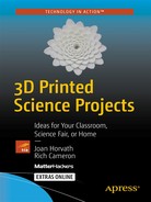
Frictional force is important with a wedge, and although the mechanical advantage here is also length divided by maximum width, how well the wedge stays put or forces in without bending matters a lot. Figure 5-1 shows the two “machines” as they were printed. Both have a 30-degree angle, but the inclined plane is a right triangle, and the wedge is an isoceles triangle to make it easier to push into place between things.
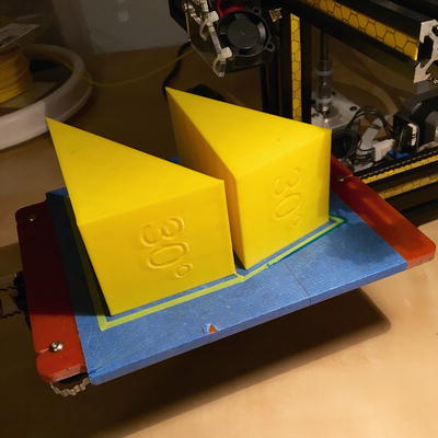
Figure 5-1. Inclined plane (L) and wedge (R), printed on their sides
Wedge and Inclined Plane Models
The model in Listing 5-1 generates both an inclined plane and a wedge (described in the next section) since one is an adaptation of the other. The model has three parameters you can change, listed in Table 5-1. We recommend that you do not make the wedge or plane a lot smaller than about half the default size shown here, since then the numbers may not print well.
Table 5-1. Wedge and Inclined Plane Variables
Variable | Default Value and Units | Meaning |
|---|---|---|
length | 100 mm | Length of longest side |
angle | 30 degrees | Angle of the plane and wedge |
width | 50 mm | Length of one side of the triangle (height of the inclined plane, max width of the wedge) |
![]() Note The model in Listing 5-1 3D prints both a wedge and inclined plane—it is not a choice based on a variable. You always get both.
Note The model in Listing 5-1 3D prints both a wedge and inclined plane—it is not a choice based on a variable. You always get both.
Lever
A lever is one of the most elegant of the simple machines. All you need is a long beam of some sort that can pivot around a supporting point (the fulcrum). Levers are often put into three categories.
Class 1 Levers
A class 1 lever has the fulcrum somewhere toward the center of the beam. Applying force downward on one side results in an upward force on the other. If the beam’s length on either side of the fulcrum is equal, there is no mechanical advantage. However, if one side is longer than the other, the mechanical advantage is the ratio of the lengths of the two sides. In principle there is no limit to how long a lever can be, but it needs to be mechanically strong enough to lift the load without snapping or breaking the fulcrum support. Figure 5-2 shows a class 1 lever on the printer, and Figure 5-3 with a load.
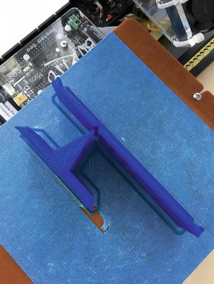
Figure 5-2. Class 1 lever on the printer
In Figure 5-3 the person’s finger is showing where to apply force. Note that the Class 1 lever has two indentations so that you can hang a weight at both ends if you want to. However, since the lever itself has finite (and unequal) mass on either side of the pivot and the pivot swings very freely, it is difficult to use this as a balance. It is best used to get a qualitative feel for the force to move an object attached to one end for a few different configurations.

Figure 5-3. Class 1 lever
You might want to print out several different positions for the fulcrum and feel the difference in force for the same weight applied to the end of each.
Class 2 and 3 Levers
Other relationships apply for the other two classes of lever. Class 2 levers have a fulcrum on one end, and a load is toward the center of the beam. An upward force on the end opposite the fulcrum will pivot the load.
A class 3 lever has the weight to be moved at one end and the fulcrum at the other. Force is applied at the marked spot partway along to pull up the load. Figure 5-4 shows a class 2 lever, and Figure 5-5, a class 3. Class 2 levers always have mechanical advantage greater than 1:1, and class 3 always worse than 1:1. Note that you have to hold the class 3 lever down at the fulcrum, too, in this design.

Figure 5-4. Class 2 lever
Figure 5-5. Class 3 lever
The model in Listing 5-2 creates a lever and fulcrum. Table 5-2 describes the variables you can change to try out different configurations.
![]() Caution The lever STL file is laid out as two pieces—the lever and the fulcrum—oriented as they would be when used with each other. For small-bed 3D printers, you might need to use MatterControl’s separation function in Edit mode to split the pair into two STLs that you can move around. See Appendix A’s section on MatterControl software.
Caution The lever STL file is laid out as two pieces—the lever and the fulcrum—oriented as they would be when used with each other. For small-bed 3D printers, you might need to use MatterControl’s separation function in Edit mode to split the pair into two STLs that you can move around. See Appendix A’s section on MatterControl software.
Table 5-2. Lever Variables
Variable | Default Value and Units | Meaning |
|---|---|---|
lever[a,b] | lever[70,30] (mm) | Length of the lever on either side of fulcrum (class 1) or load/resistance application point (class 2 or 3) |
class | 1, 2, or 3 | Type of lever |
width | 30 (mm) | Width of lever and fulcrum |
Screw
We usually think of a screw as something that holds things together. More generally, though, turning a screw takes rotational motion and changes it into linear motion along the screw’s axis. 3D printers often use a screw to drive one or more of their axes.
Screws used as fasteners (for example, machine screws with nuts) are designed to use mechanical advantage to convert rotational force into tensile and compressive forces to produce friction to hold things in place.
The mechanical advantage of a screw is proportional to how far apart the threads are (the pitch); the closer they are, the higher the advantage. However, screws are usually far off the ideal for most practical purposes because there is so much friction on a screw embedded in a material. Wikipedia has a very good brief explanation at https://en.wikipedia.org/wiki/Screw_%28simple_machine%29.
Our example of this simple machine is a model of a vise (the real thing in Figure 5-6, and our model in Figure 5-7). The model prints in just two parts: the upper crossbar and the rest of the model. The knob to turn the screw is printed in place (captive). This is an example of a model that is not really possible to create any other way than by 3D printing it (if it is being fabricated in one piece, anyway).

Figure 5-6. A vise
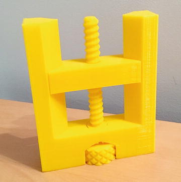
Figure 5-7. Vise (screw) model
The printed vise of course is not strong enough to use for anything that will exert a lot of force, but it will be interesting to play with and get some intuition about the relationships between the things you can vary for this model. The variables you can tweak are listed in Table 5-3; the model for the vise model is in Listing 5-3.
Table 5-3. Vise Model Variables
Variable | Default Value and Units | Meaning |
|---|---|---|
fn | 12 | Sides used to approximate circles (raise for smoother print) |
tolerance | 0.4 mm | Tolerance between moving parts—raise if parts are binding, lower (a tiny bit) if too loose |
pitch | 4 | Screw pitch (see narrative) |
The vise model should be printed in the same orientation shown in Figure 5-7 (vertically), with the crossbar piece flat on the platform next to it. If you screw the crossbar all the way to the bottom, you will discover that there is a slight gap. This is intentional, to orient the layers of the crossbar to allow smoother movement by preventing the layers from catching on one another.
Wheel, Axle, and Pulley
A wheel and axle are very similar to a pulley. As a result, we have a model that will generate both, depending on a parameter. We talk about each machine and then introduce the model that creates one or the other (based on setting a variable to true or false).
Wheel and Axle
The combination of a wheel and axle appears to have been around the longest of all the simple machines. The first known instances were in Mesopotamia between 5,000 and 6,000 years ago. A wheel makes it easier to move things by allowing a large force at the hub to be translated to a smaller motion at the rim, creating mechanical advantage. Wheels also reduce frictional resistance with the ground by having a small contact area with the ground; friction in a wheel occurs at the axle. Wheels also function like a variable-angle inclined plane at their leading and trailing edges as they roll over the ground, smoothing out any bumps in the surface they roll over.
Some ancient civilizations (including the Egyptians) managed engineering feats without the wheel or the pulley. In modernity, wheels are usually seen in combination with other simple machines, like the combination of lever and wheel and axle we see in the humble wheelbarrow (Figure 5-8). The wheel allows the user to move around heavy loads, and the handles (levers) allows hoisting the barrow up onto its wheel. (Otherwise, it rests on its feet.)
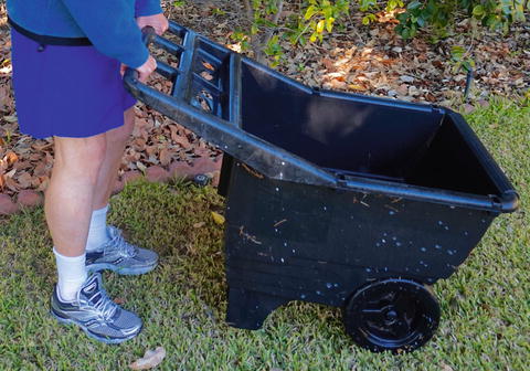
Figure 5-8. Wheel and axle, combined with a lever, in a modern wheelbarrow
Pulley
A pulley is a wheel and axle with a groove around the wheel’s rim. A rope, chain, or belt of some sort goes into the groove and supports a weight. In the simplest form, a pulley just changes the direction of a force, but not its magnitude. The idler pulley in Figure 5-9, for example, changes the direction of the cable running over it, which in turn is pulling around the y-axis of a 3D printer.
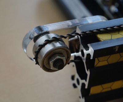
Figure 5-9. Idler pulley on a consumer 3D printer
If more than one pulley is used, then the weight of an object is distributed over several sections of rope. A block and tackle and related, more-complex devices exploit this feature. The mechanical advantage depends on the number of pulleys, their distribution, and how the rope is attached—look up “block and tackle” to see some examples (a good one is this Wikipedia article: https://en.wikipedia.org/wiki/Block_and_tackle). The diameter of a pulley typically does not affect its mechanical advantage. The exception is when a pulley’s axle is attached to something else, such as a pulley with a different diameter, so that the two turn together.
Wheel and Pulley Models
The same OpenSCAD model creates a sample pair of four wheels on two axles, or an arbitrary string of pulleys on one frame. The variables you can adjust are in Table 5-4, and the model is in Listing 5-4.
Table 5-4. Wheel and Pulley Variables
Variable | Default Value and Units | Meaning |
|---|---|---|
wheel | true (wheels) | Select wheels or pulleys |
false (pulleys) | ||
clearance | 0.4 mm | Spacing between wheels or pulleys and hub, must be loose enough to allow free rotation |
pulley_width | 8 mm | Width for pulleys |
wheel_width | 20 mm | Width for wheels, should be greater than min_diameter |
spacing | 3 mm | Between pulleys or wheels |
loop | 8 mm | Diameter of loop and hook at either end |
count | 2 mm | Number of pulleys (wheels are always 2) |
min_diameter | 20 mm | Min size of pulley or wheels |
diameter_step | 5 mm | How much bigger to make each pulley when doing multiples |
csec_d | 5 mm | Cross-sectional diameter of pulley frame |
![]() Note The wheels or pulleys take a while to render in OpenSCAD. Do not close the window while OpenSCAD is calculating and rendering.
Note The wheels or pulleys take a while to render in OpenSCAD. Do not close the window while OpenSCAD is calculating and rendering.
Assembling and Using Wheel and Pulley Models
These models need a bit of assembly. Figure 5-10 is a set of wheels on the printer bed. Figure 5-11 is a one-pulley set and a two-pulley set printed at the same time. Figure 5-12 is the assembled wheel set, and Figure 5-13, the pulleys. The wheels (or pulleys) go on their axles and then are secured with the small C-shaped clips.
Figure 5-10. Wheel pieces, as printed
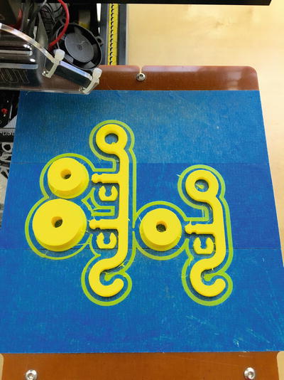
Figure 5-11. One-pulley and two-pulley set, as printed together (two OpenSCAD runs)
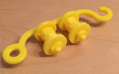
Figure 5-12. The wheels printed in Figure 5-10, assembled
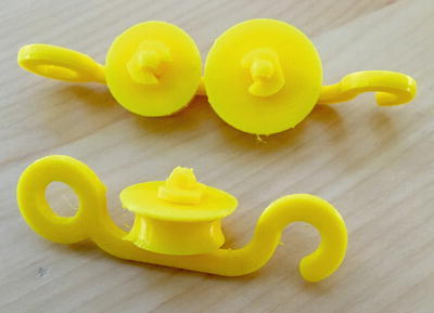
Figure 5-13. The pulleys printed in Figure 5-11, assembled
Obviously, if you want to demonstrate wheels, there are any number of pull-toys you can use. Our entry here is intended to be a base that you can add to or scale for specific demonstrations. You can play with various surfaces and explore how much friction is needed for something to roll (versus sliding), for example.
We talked about pulley mechanical advantage earlier in this section. Figure 5-14 shows a block and tackle (one of many designs) assembled from the pulleys in Figure 5-13 (and only using one of the pulleys on the double set).
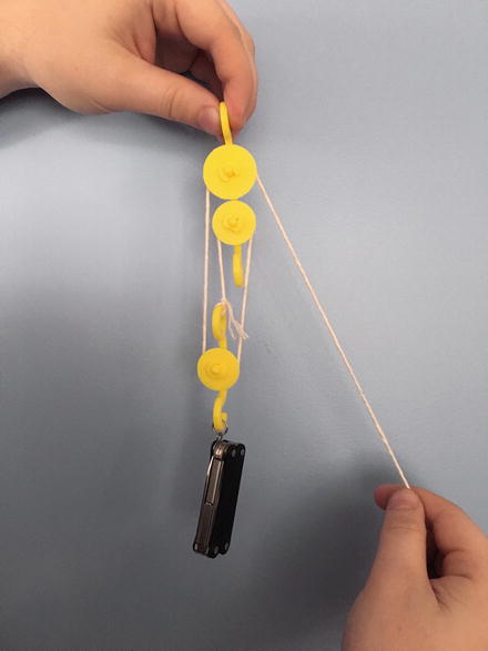
Figure 5-14. Block and tackle
Printing Suggestions
These models can be scaled up (made bigger), but only the wedge and inclined plane can safely be made smaller. The other models may have tolerance issues if they are made too small. The screw model is something of a precision part, and we suggest that you print it only in the orientation that the current OpenSCAD model creates. Generally it will be better to change the scaling variables in OpenSCAD than to use 3D printer software scaling functions.
We have a picture of each of the models as-printed and an additional one of the model in use for the more dynamic models. Depending on your print bed size you may be able to print several at once. Each model also had a list of the parameters you can save easily.
We printed all these models in PLA, without support, typically with about 15% infill.
THINKING ABOUT THESE MODELS: LEARNING LIKE A MAKER
Unlike many of the other models in this book, these did not start with an abstraction. Rather, they are prints of things that are normally 3-dimensional objects. In the course of creating them, we did not struggle to think about how to represent them, since the objects are physical already. Here, the challenge is that these building blocks are normally part of more complex wholes. You will need to spend some time thinking about what you want to learn (or teach) from these models to decide which ones to print out and how to arrange them to do something useful or to demonstrate a principle.
Mechanical advantage can, for the most part, be shown with a string taped to a weight (a few coins, possibly). The previous talks about the issues of matching scale and integrating these into more-complex models. We encourage you to try these out and see what you can construct.
Where to Learn More
Since simple machines are a required topic in many elementary and middle school curricula, there are correspodingly large numbers of online games and student and teacher support materials available online. Try searching for simple machine games. We were particularly charmed by ones from the Museum of Science and Industry in Chicago (www.msichicago.org/play/simplemachines/) and another from the group Edheads (www.edheads.org/activities/simple-machines/). These videos use common items to demonstrate or identify simple machines.
The definition of simple machines is a little arbitrary. Different disciplines have varying opinions about what the simple machines include. Sometimes gears are included as a distinct seventh simple machine; others feel that meshing gears are really a wheel and axle combined with wedges. Either way, there are already a lot of fun gears available to 3D print, so we will not add to the supply. Search gears on www.thingiverse.com, but be careful to check the comments to see if the design has actually been proven out.
If you are feeling like trying something a little harder, you can try Rich’s quick print gear bearing (Figure 5-15) instructions at www.youmagine.com/designs/quick-print-gear-bearing (based on one by Emmett Lalish, at www.thingiverse.com/thing:53451). These gears (a set of planetary gears) print very fast relative to other 3D-printable gears and are fun for demonstrations. They are a little tricky though—you are printing the hollow spaces inside the model, not the model surface itself (Figure 5-16). This can be done with creative use of slicing program settings. The gears come off the printer ready to turn once you wiggle them a little to free them up.

Figure 5-15. Rich’s quick print gear (prints assembled, just as shown)
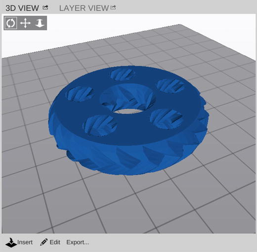
Figure 5-16. What the model looks like in MatterControl—you are printing the empty space, not the modeled surface
Our book 3D Printing with MatterControl uses printing this gear as an advanced slicing exercise (Figures 5-15 through 5-17 are from Chapter 10 of that book). Figure 5-17 gives the MatterControl preset that works with these gears, assuming you are using MatterSlice. Appendix A talks more about MatterControl in general.

Figure 5-17. Rich’s quick print gear settings in MatterControl
Teacher Tips
Since simple machines are so ubiquitous, one simple thing to do is to have students look around at common household or classroom objects and deconstruct them to find the simple machines. Kitchen hand tools are particularly rich sources of machines. These everyday hand tools can be surprisingly complex. Then you can have students design their own combinations of simple machines to solve some theme or problem.
Some schools have given students projects to recreate historic machines, sometimes with a twist. For example, Castilleja School’s Bourne Idea Lab (www.castilleja.org/bournidealab) had students recreate some of Leonardo DaVinci’s machines, with some modern twists.
Generally the topics around simple machines are covered in the NGSS Forces and Interactions standards (MS-PS-2, www.nextgenscience.org/msps2-motion-stability-forces-interactions) and Energy standards (MS-PS-3, www.nextgenscience.org/msps3-energy). University of Colorado, Boulder also has a set of lesson plans, with alignment to various standards, at www.teachengineering.org/view_lesson.php?url=collection/cub_/lessons/cub_simp_machines/cub_simp_machines_lesson01.xml.
Science Fair Project Ideas
When these simple machines meet up with the real world, non-ideal effects like friction come into play. You might characterize some of these real-world effects and find a systematic way to manage them to minimize inefficiency. Analyze what existing products do to be efficient and think about what you might change to do something better.
Getting a little more into product design issues, you might think about how machines meant for humans to use without additional power (hand tools, daily-use objects) might be more or less efficient for people with different size hands or in different environments (for example, wearing gloves or not). You could also look into what kinds of things make these simple machines break or not work very well, and what enhancements are the best shields against that.
Some good books on both good user experience design and the origins of classic mechanisms are Donald Norman’s The Design of Everyday Things (Basic Paperbacks, 2002) and Henry Petroski’s books on how things fail when good design principles are violated. Petroski’s classic work is To Engineer Is Human: The Role of Failure in Successful Design (Vintage, 1992), but he also has entire books focused on a few particular inventions, such as the toothpick.
Summary
In this chapter, we learned about how to 3D print six simple machines: wheel and axle, pulley, inclined plane, wedge, lever, and screw. We covered a bit of the history of these machines, how they generate mechanical advantage, and how to print them. We wound up with some ideas on how to demonstrate the idea of a simple machine with historical recreations, or perhaps some research into good product design.