
CHAPTER 4
Projects Using SketchUp Pro and Extensions
IN CHAPTER 3 WE USED SketchUp’s native tools and made a component. In this chapter we’ll download more tools called extensions. These enable you to perform operations the native ones can’t. We’ll also download and edit models from the Warehouse and another online site called Thingiverse and use SketchUp Pro’s solid tools. This chapter’s projects are a bench, a Halloween fingernail, a chocolate mold tray, an architectural terrain model, a Pac man ghost, and a floor plan.
Components
Access the Warehouse by clicking on Window > Components. A navigation browser will appear (Figure 4-1) showing two folders of component collections. The Sample collection is open by default. Click on the drop-down arrow to see more collections (Figure 4-2). You can drag and drop their components from their thumbnails into the workspace. Click on the House icon to see which components are currently in the model. Be aware that even after you delete a component from the model, it still remains in the file. Having many components contributes to a large file size, and that slows the model down. Get rid of unused components by clicking the House’s fly-out arrow and then clicking Purge Unused (Figure 4-3).
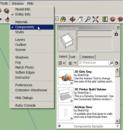
Figure 4-1 The Components browser with the Sample collection open.
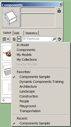
Figure 4-2 Click the drop-down arrow to see more Component collections.
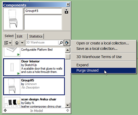
Figure 4-3 Purge unused components with the House icon’s fly-out arrow.
Type what you’re looking for in the Navigation browser’s search field, and scroll through the thumbnail results. Click on one to download the component, and drag and drop it into the workspace. I downloaded the component shown in Figure 4-4.

Figure 4-4 Download a Warehouse component via the Navigation browser’s search field.
This component consists of four chairs and a scale figure, each of which is a separate component. So we’ve got five components nested inside one large shell component.
I only want one chair, so double-click the editing box open and delete everything but one chair. Highlight that chair and explode it. This removes its outer shell, leaving just the component chair (Figures 4-5 and 4-6). Don’t explode that.

Figure 4-5 Open the component editing box, and delete unneeded items.
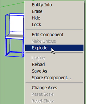
Figure 4-6 Select and explode the outer shell, leaving the remaining chair component intact.
This is an example of a simple edit. Warehouse models usually need some editing to make them suitable for your own purposes. Know that anyone can upload to the Warehouse, and there is no vetting. The SketchUp team uploads models, companies upload models of their products, and casual SketchUp users upload their creations. There are replicas of whole buildings and cities, and rooms filled with brand-name furniture, fixtures, and equipment. Excluding branding and logos, all content is free and can be used for both personal and commercial purposes. SketchUp also has a partnership with the online service bureau i.materialise.com; hence, you can access its large inventory of 3D-printable models through the Warehouse. Most user-uploaded Warehouse components are not 3D-printable as-is, but many can be edited to be made so.
While many models are great, others are bloated (huge file size) or have other problems. When you download a model, you download everything in it—imported images, layers, and possible corrupted elements. Before downloading a Warehouse model into a model that you’ve spent hours working on, download it into a new file first to check it out.
What’s an Extension?
An extension, also called a plug-in, script, or ruby (named after its programming language), is a simple text file with an .rb or .rbz suffix at the end of the file name. It plugs into SketchUp to extend its native capabilities, much like a phone app. Extensions can bend 3D text, perform energy analyses, add light, and more. Most are written by third-party developers. Many are free, and others have a cost. They work with both Make and Pro.
The Extension Warehouse
The best source of extensions is the Extension Warehouse (EW). It contains both free and pay ones. Access it through its toolbar icon (top graphic, Figure 4-7).
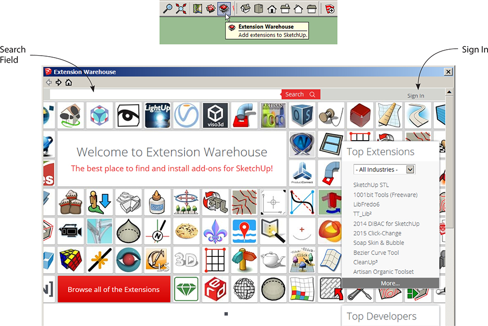
Figure 4-7 The Extension Warehouse icon and homepage.
At the top of the EW homepage is a search bar and login box. You can browse what’s there without logging in, but you need to log in with a Google account to download anything. So log in, and then mouse over the login box to see its options. My Extensions accesses a list of every extension you’ve downloaded (Figure 4-8), which is useful when you want to return to an extension’s page. The EW homepage displays the extensions that are most popular at the moment. You must have the IE or Safari browser installed and set as default to access the EW from within SketchUp.
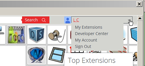
Figure 4-8 Once logged in, you can download extensions and access these options.
We’re going to download seven extensions in this chapter: TT Lib2, Bezier Curves Tool, CLF Shape Bender, Shell, SketchUp Stl, s4u Make Face, and Add Terrain Skirt. The first six are in the EW, and the last one is at sketchucation.com.
Download the Extensions
Download TT Lib2 first (Figure 4-9). Do a search for it, or if it’s visible in the Popular Downloads box, click there to access its page. This extension is a collection of background utilities that some other extensions need to work.
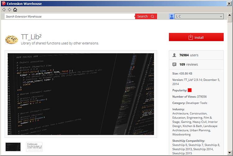
Figure 4-9 The TT Lib2 page.
When logged in, you’ll see a red Install button on the extension page. Click it. You’ll be asked for permission to install and notified when it’s done (Figure 4-10). Because extensions are executable files, be careful about downloading them from other websites. Legit outside sources exist, but everything in the EW has been vetted by the SketchUp team. After you install TT Lib2, the red button will say Uninstall.
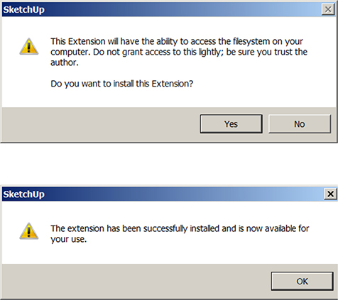
Figure 4-10 Dialog boxes that appear during the download process.
After downloading your first extension, an Extensions entry will appear in the menu at the top of the SketchUp screen. At Windows > Preferences > Extensions the downloaded extension will appear in a list (Figure 4-11). Note that there are some native extensions there, too. An extension’s box must be checked for it to work.
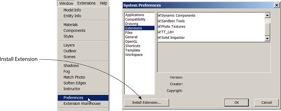
Figure 4-11 At Windows > Preferences > Extensions is a list of all native and downloaded extensions. Extensions that require TT Lib2 to work need to appear listed below it.
Extensions that need TT Lib2 to work will prompt you to download it if they can’t find it on your computer. Some of these extensions don’t work unless TT Lib2 appears above them in the extensions list. So if you’ve already downloaded an extension that requires TT Lib2, but you can’t find that extension’s tool—or it doesn’t work—check its location in the list. If the extension is listed above TT Lib2, uninstall it (but keep TT Lib2). Then reinstall it. It should appear listed below TT Lib2 now, and the tool should work.
You can access the EW directly on the Web at https://extensions.sketchup.com, but downloaded extensions won’t install automatically. In that case, and for extensions downloaded from other websites, click on the Install Extension button. If the Install Extension button doesn’t work, drag the extension file or folder (don’t remove a folder’s contents) manually into the Plug-ins folder on your computer’s program files. SketchUp 2015’s path to this folder is Windows C:UsersYOUR USERNAMEAppDataRoamingSketchUpSketchUp 2015SketchUpPlugins. Mac OS X users, go to User/Library/Application Support/SketchUp 2015/SketchUp/Plugins.
Search for and install Bezier Curves, CLF Shape Bender, Shell, SketchUp Stl, and s4u Make Face (Figure 4-12). The Bezier Curves extension draws French curves, which are noncircular arcs. The Shape Bender bends groups and components along a pre-drawn path. Shell applies thickness to a curved plane. SketchUp Stl imports and exports a model as an .stl, the most popular file format for 3D printing. s4u Make Face creates a face inside a coplanar outline.
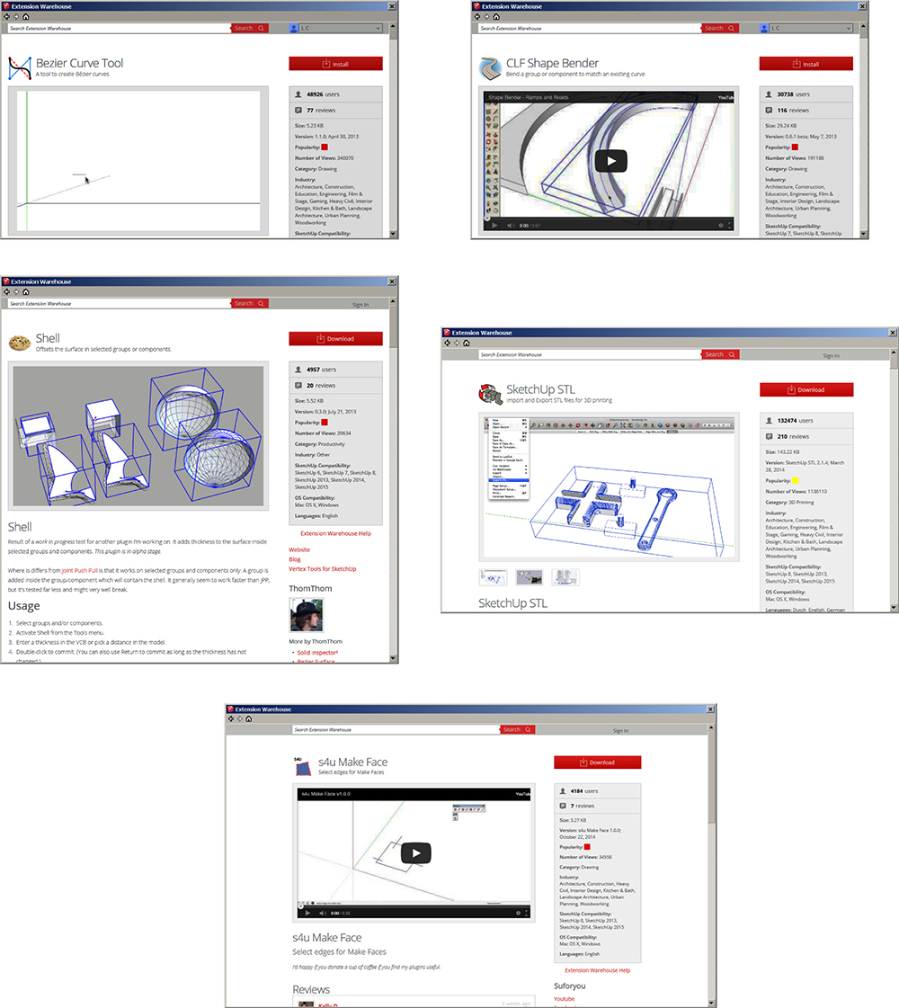
Figure 4-12 The Bezier Curves, CLF Shape Bender, Shell, SketchUp Stl, and s4u Make Face pages.
Each extension’s page has a short video and instructions. They’re written by the developers, and because some instructions are more informative than others, an extension may take some experimentation to figure out.
Where to Find the Extension Tools
Some extension tools are accessed through the Extensions menu at the top of the SketchUp workspace. Others appear as an entry in the Tools or Draw menu or as a submenu under one of them. Some appear in a context menu when the appropriate geometry is right-clicked. If the extension has a toolbar, it might appear in the workspace immediately on installation, You might have to check its box at View > Toolbars first, or check its box in the Preferences > Extensions list. Or you might have to close and reopen the SketchUp file for it to appear. Let’s look at the Bezier Curves extension now.
How to Use the Bezier Curves Tool
Draw and group a rectangle to serve as a drawing plane. Then click on the Draw menu to activate the Bezier Curves tool (Figure 4-13).
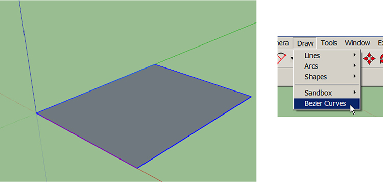
Figure 4-13 Draw and group a rectangle; then activate the Bezier Curves tool.
Drawing a Bezier arc takes four clicks (Figure 4-14). Click the two endpoints. Adjust the arc and click again. Click a fourth time to adjust the arc further and set it, or hold its position and click to set it. Watch for the On Face inference each time you click. To cancel the operation while drawing the arc, click Escape.

Figure 4-14 Drawing a Bezier curve.
After the arc is set, you’ll still be in the Bezier Curves tool. Click the Select tool to get out of it. To edit the curve, right-click on it and choose Edit Bezier Curve (Figure 4-15).

Figure 4-15 Right-click the Bezier curve to edit it.
Bench Project
We’re going to use the Bezier Curves and CLF Shape Bender tools to turn the chair component we downloaded earlier into a long, curved bench that looks like Figure 4-16. The CLF Shape Bender tool only works on groups and components, not loose geometry.

Figure 4-16 A curved bench made with a chair and two extensions.
1. Make a rectangle and group it. Then draw a Bezier curve on top of it (Figure 4-17).

Figure 4-17 Make a rectangle, group it, and draw a Bezier curve.
2. Draw a line that’s the width of the chair and runs along the red axis (Figure 4-18). Running along the red axis is critical, so watch for the red inference line.

Figure 4-18 Draw a line that’s the width of the chair and runs along the red axis.
3. At View > Toolbars, turn on the CTL Shape Bender toolbar (Figure 4-19).
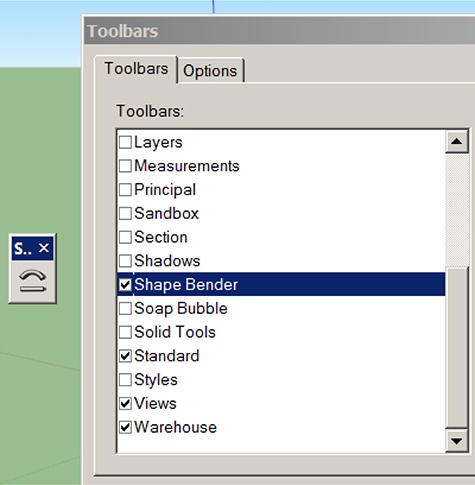
Figure 4-19 Turn on the CTL Shape Bender toolbar.
4. Highlight the chair and then click on the CTL Shape Bender tool. The cursor will turn into an arrow and line (Figure 4-20).

Figure 4-20 Hightlight the chair and then click on the CTL Shape Bender tool.
5. Run the cursor over the red axis line drawn in step 2. When it turns blue, click it. The words “Start” and “End” will appear (Figure 4-21).
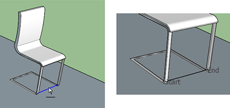
Figure 4-21 Click the tool onto the red axis line to select it. “Start” and “finish” will appear.
6. Run the cursor over the Bezier curve drawn in step 1, and click. The chair will extrude along its length (Figure 4-22). Hit the UP ARROW key on the keyboard to reverse its position if needed. Then hit RETURN to set.

Figure 4-22 Click the Bezier curve to extrude the chair. Hit the UP ARROW key to reverse its position if needed.
7. The bench (Figure 4-23) needs some cleaning up, which is common with this extension. The extra face that formed near the curve can be selected and deleted. The thick line along the back of the seat is actually two double lines that can be selected and deleted. The Bezier curve also should be deleted. You might want to copy the legs, add a few more, and perhaps extrude them around the Bezier curve, too.

Figure 4-23 The extruded bench.
Fake Fingernail Project
How about some fake fingernails for Halloween? Let’s make one (Figure 4-24) with the CTL Shape Bender and Shell. Take a straight-down photo of your index finger to use for tracing. This will make the nail truly custom to your finger.

Figure 4-24 Fake fingernail.
1. Click File > Import, make sure the Use as Image button is checked, and import the photo. Don’t worry about its size because we’ll scale it later. Click the Top view on the Views toolbar. Then activate the Two Point Arc tool, and draw an arc over one cuticle (Figure 4-25). Remember to look for the On Face inference with each click, and to pull the arc straight along the green axis. Just as with a circle, you can change the arc’s default number of segments by typing the number you want immediately after clicking it onto the work plane.

Figure 4-25 Import a photo of a finger and draw an arc on one cuticle.
2. Copy and mirror the arc (Figure 4-26). Use MOVE + CTRL (or CTRL + C and CTRL + V) to copy it. In Chapter 3 we used Flip Along in the context menu for mirroring, but that function doesn’t show up on a non-grouped arc. Instead, click the Scale tool on the arc, push the top-middle grip down a bit, and then type −1. The arc will flip.

Figure 4-26 Copy the arc, and then mirror it with the Scale tool.
3. Draw a straight line down from the first arc, and connect it to an endpoint on second arc (Figure 4-27). If the line is too long, move the arc up the line’s length, and trim excess with the Eraser.
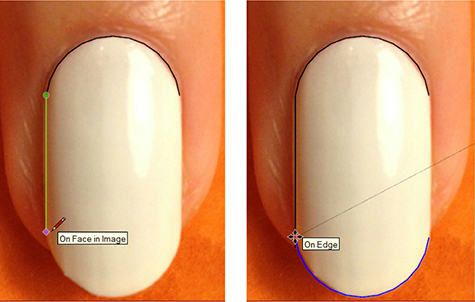
Figure 4-27 Draw a line down from the first arc, and connect the second arc to it.
4. Draw the nail’s other side to finish the shape (Figure 4-28). A face will form. If the blue side is up instead of the white side, select the whole nail, right-click, and choose Reverse Faces.
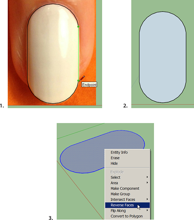
Figure 4-28 Finish the nail’s shape, and reverse faces if needed, so that the white face is on top.
5. OPTIONAL: If you want to extend the nail’s length, select an arc, click the Move tool on it, and stretch it along the green axis (Figure 4-29). If you want to customize the top of the nail with any kind of geometry, now is the time to do it.
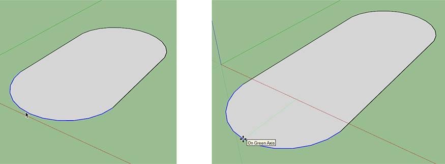
Figure 4-29 To make the nail longer, select an arc, and stretch it with the Move tool.
6. Group the nail. Then make a rectangle to use as a drawing surface and group it. Move the nail onto the rectangle (Figure 4-30). By now you may have noticed the “flashing” that occurs when two planes are adjacent. This happens because SketchUp doesn’t know which plane to display. It doesn’t affect anything, though.

Figure 4-30 Move the grouped nail onto a grouped rectangle.
7. Draw a line and an arc to use with the CTL Shape Bender tool (Figure 4-31). Remember to draw the line on the nail along the red axis. Inference the arc from the edges of the nail to make it the same length as the nail. Draw the arc’s bulge along the blue axis.
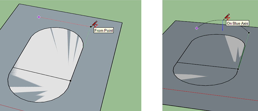
Figure 4-31 Draw a line and arc to use with the CTL Shape Bender tool.
8. Use the CTL Shape Bender extension to curve the nail (Figure 4-32). To recap: select the grouped nail, click on the tool, click on the red axis line, click on the arc, and press RETURN.

Figure 4-32 Curve the nail with the CTL Shape Bender extension.
9. Give thickness to the nail (Figure 4-33). Push/Pull doesn’t work on curved surfaces, so use the Shell extension. It offsets groups and components with a second group or component. First, highlight the grouped nail and then click on Tools > Shell. A second component will appear, and you’ll see its default offset in the Measurements box. Type the offset you want; because we never scaled the nail, eyeball something proportionate. Then hit ENTER.
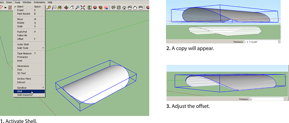
Figure 4-33 Use the Shell extension to give the nail thickness.
10. Scale the nail (Figure 4-34). Measure the width of your fingertip, click the Tape Measure on opposite edges of the model’s width, type the measurement, and press ENTER. The nail will scale to that size, customized to your finger! You might need to click on Zoom Extents to find it.

Figure 4-34 Scale the nail to make it 1" long.
Right now the nail consists of two groups: the original and the one made with Shell. Make a copy of this model. Keep the original as-is. On the copy, explode both groups (Figure 4-35). Then select the whole nail and group it. This may help make the model more 3D-printable.
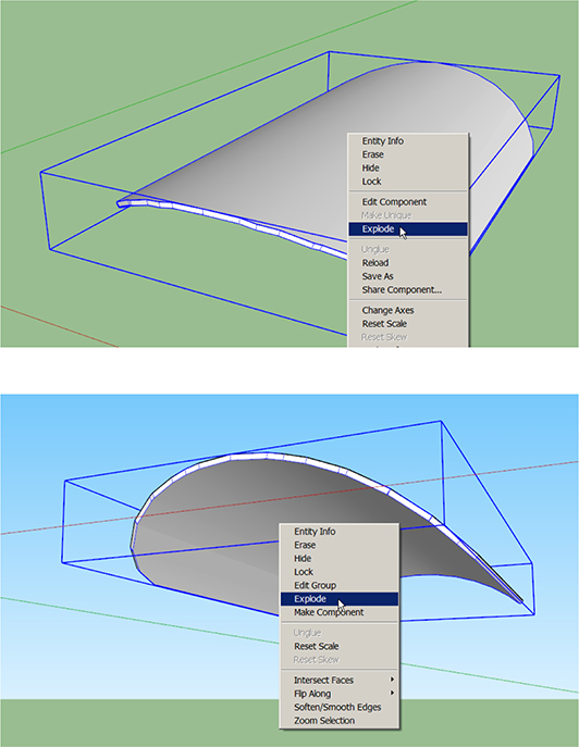
Figure 4-35 Explode the original and offset components, and then make one group that contains both of them.
Done! There’s a company that 3D prints nails like this with precious metals. Figure 4-36 shows some of their offerings.
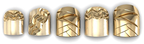
Figure 4-36 3D-printed nails by https://www.facebook.com/CLAWZco?hc_location=ufi.
Before moving on to our next project, let’s talk about two subjects that will be used in it: Thingiverse, solid geometry, and solid tools.
Thingiverse
Thingiverse is a model repository. Like the 3D Warehouse, anyone can upload to it, and you’ll find thousands of models (“Things”) made by professionals and casual users. Unlike the models in the 3D Warehouse, most models in the Thingiverse are covered by a Creative Commons copyright. Thingiverse allows sharing but also maintains owners’ rights.
Most Thingiverse files are in .stl format. Sometimes you find other files as well, such as the original model, which enables you to easily edit it if you have the software program it was made in. Find SketchUp files for Things by using SketchUp as a search term. When you find something you like, click on it and then click the Download This Thing! button. Then download and unzip any zipped files. I searched for Space Invaders and found the files shown in Figure 4-37. Coincidentally, there were even two SketchUp files.

Figure 4-37 This Thing consists of three Space Invaders .stl files and two SketchUp files.
Solid Geometry
Because SketchUp is a mesh modeler, it makes hollow models. They’re just faces and edges, empty inside: think air-filled balloon. Solid modeling programs make models with a continuous volume: think rock. So a SketchUp solid isn’t like a solid made with a solid modeling program such as Autodesk Inventor. “Solid” in SketchUp simply means closed geometry. If the model held water, none would leak out.
When you draw a rectangle, push/pull it up and group it, you’ve made a solid. Loose geometry cannot be a solid; it must be a group or component. Verify whether a group or component is solid by highlighting it, right-clicking, and choosing Entity Info. If it says Solid Group or Solid Component, it’s solid. If it just says Group or Component, it’s not solid; there’s a hole or extra piece of geometry somewhere in it. Figure 4-38 shows examples of solids. Note that the solid’s volume is also shown, which is useful when calculating material costs for 3D printing.
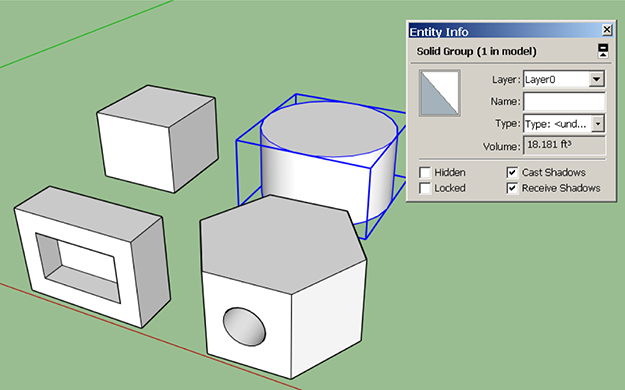
Figure 4-38 SketchUp solids are closed geometry made into a group or component. The Entity Info box verifies if a model is solid.
Know that it can be tricky to make a solid that’s more complicated than a pushed/pulled rectangle. Because a tiny face or edge embedded inside will prevent it from being solid, a solid group often becomes unsolid very quickly. We’ll discuss troubleshooting tools in Chapter 5.
Solid Tools
Solid tools let you do things that would be impossible or take a lot of steps with native tools. SketchUp has six; activate them at Views > Toolbar > Solid Tools. The first one on the toolbar, Outer Shell, is available with Make. The rest are Pro features. Solid tools only work on solid geometry, and they work differently than native tools. Basically, you push solids together and then choose what operation you want to perform by picking a specific Solid tool. Once a Solid tool operation has been performed, a model’s parts can’t be individually edited anymore. So it’s good practice to save a copy of the model first.
In the following project we’ll use the Subtract tool to subtract one solid from another.
Chocolate Mold Tray Project
Let’s make a tray with custom molds to fill with chocolate, Jello, or ice cubes (Figure 4-39).

Figure 4-39 A chocolate mold tray made with a downloaded .stl file and Solid tool.
Install the SketchUp Stl extension. This enables the import of .stl files, which are basically shells around mesh models. Then go to File > Import and scroll through the Files of Type field to Stereo Lithography Files (Figure 4-40). Navigate to the one you want and click Open (or hit ENTER). The .stl files display the icon of a program that can open them, in this case 123D Meshmixer. Click the Options button, check Merge Coplanar Faces, set the units to the receiving file’s units, and click Preserve Drawing Origin. The file will import at SketchUp’s origin and may be very small; click Zoom Extents to find it (Figure 4-41).

Figure 4-40 Once the SketchUp Stl extension is installed, you can import an .stl file.
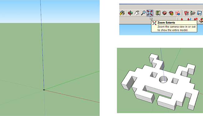
Figure 4-41 The .stl file will import at the origin. You may need to click Zoom Extents to find it.
I imported the three Space Invaders .stl files downloaded from Thingiverse. Here are steps to make the tray:
1. Group each model separately; then rotate and copy them (Figure 4-42).

Figure 4-42 Group the models, rotate for better positioning, and copy.
2. Draw and group a rectangle, and move it under the models (Figure 4-43). Adjust the rectangle’s size as needed by highlighting and stretching its edges with the Move tool. Then give it some thickness with Push/Pull (remember to open the group editing box) to make it a base.
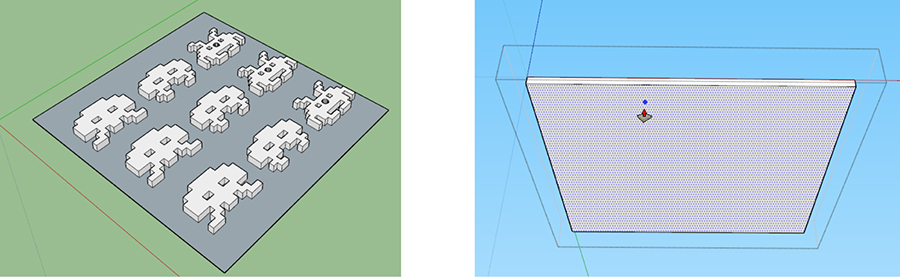
Figure 4-43 Place a grouped rectangle under the models and give it thickness.
3. Move the models part way into the base (Figure 4-44). Not all the way, just part way. The amount they’re pushed inside the base determines the mold’s depth. Pushing the models almost all the way down will make deep molds, and pushing them in just a little will make shallow molds. Press and hold the UP ARROW key to inference lock them along the blue axis, which makes moving them straight down easier. If they won’t move down at all, right-click on them and choose Unglue.
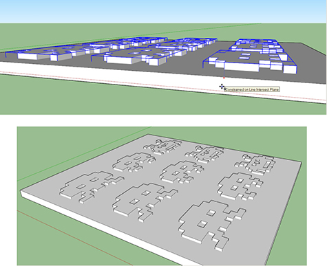
Figure 4-44 Move the models partway into the base.
Note that there is no edge line between the Space Invaders and the base (Figure 4-45). We’ve used the Intersect Faces with Model function before to create one, but now we’re going to use the Solid Subtract tool.

Figure 4-45 Edges did not form when the models were moved into the base.
4. On the Solid Modeling toolbar, activate the Subtract tool. Click a Space Invaders figure first and the base second (Figure 4-46). The Space Invaders model will get subtracted from the base. Note the exposed cylinder; select and delete it (Figure 4-47).
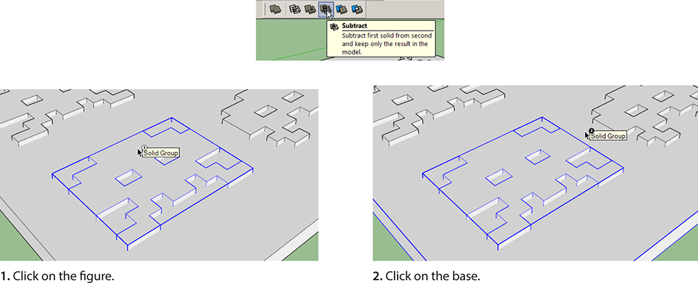
Figure 4-46 Subtract the Space Invaders model from the base with the Subtract tool.
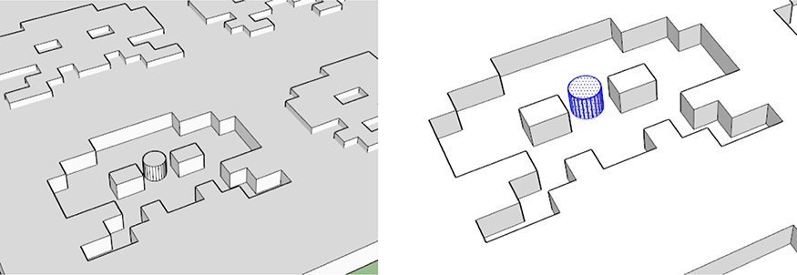
Figure 4-47 After this figure is subtracted from the base, the exposed cylinder can be selected and deleted.
The order in which you click makes a difference because the first item gets subtracted from the second. When finished, scale the whole model by clicking the Tape Measure on opposite corners and typing the dimension wanted. Done!
Architectural Terrain Model Project
Terrain models show a patch of ground’s topography: slope of the earth, vegetation, and built features. They’re used to study a site and building placement. Ours uses an extension that isn’t in the EW. Point your browser to http://sketchucation.com/. Make an account, log in, and click on the Plug-in Store tab (Figure 4-48). Then search for Add Terrain Skirt. Download the file, and install it by clicking on Window > Preferences > Extensions and on the Install Extension button.
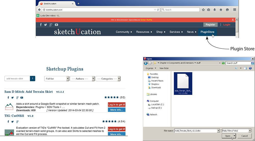
Figure 4-48 Download the Add Terrain Skirt extension from sketchucation.com and install it at Window > Preferences > Extensions.
1. Find the general area (Figure 4-49). Click on File > Geo-location > Add Location. This accesses a world map. Type what you’re looking for in the search field—an exact address, name of city, state, even landmark. The slider on the left lets you zoom in and out.

Figure 4-49 Search with the Geo-location feature.
2. Find the exact area (Figure 4-50). Once you’ve zoomed in to the general area, click on Select Region. Four pins will appear. Move them to select the exact patch wanted for the model. Include a feature whose size you know or can reasonably guess. Then click Grab.

Figure 4-50 Select the exact area for the model by adjusting the pins.
3. Unlock the patch (Figure 4-51). The patch of Google Earth terrain will load into the model. It’s a grouped photo. Click on it to select. Note that the group border is red, meaning that it’s locked. Right-click and choose Unlock. It should enter to scale, but if it doesn’t, click the Tape Measure on opposite ends of a feature whose size you know, and type the correct size. The whole model will scale proportionately.

Figure 4-51 Google Earth layers.
4. Access the patch’s slope (Figure 4-52). Google Earth terrain comes with a turned-off layer or sheet containing slope information. Click on Window > Layers and check the box next to Google Earth Snapshot. This makes that layer visible. Then uncheck the Google Earth terrain patch because we don’t need it anymore.
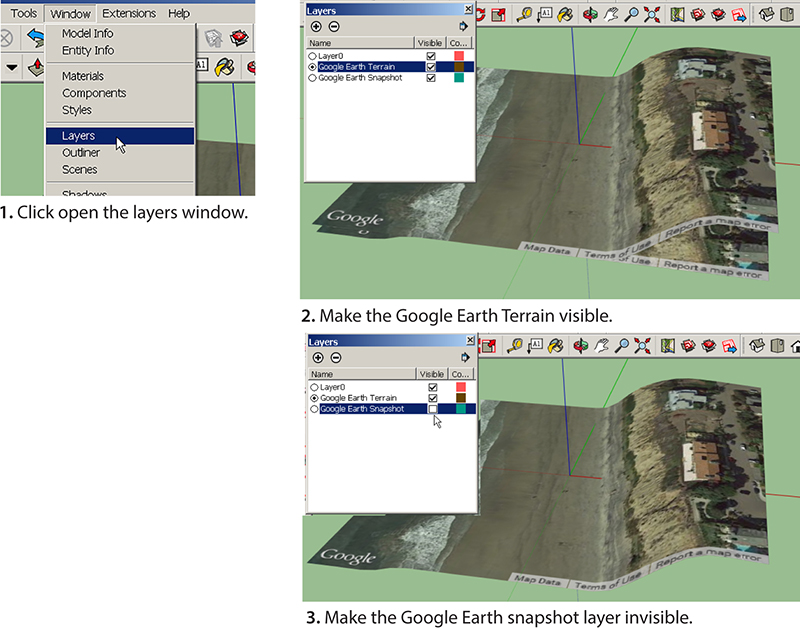
Figure 4-52 Google Earth layers.
5. Add volume to the model. Clicking on the slope, you’ll see that it’s another locked group. You can right-click to unlock it if you want, but it’s not necessary. Select it, then click on Extensions > Add Terrain Skirt (remember, we installed it earlier). Volume will automatically be added to the selected group (Figure 4-53), and you can push/pull it thinner or thicker. Done!
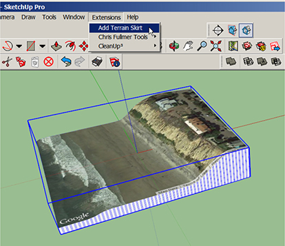
Figure 4-53 The Add Terrain Skirt extension adds thickness to the terrain model.
If you want to crop the watermark on the Google Earth Terrain picture or trim overlapping mesh from multiple patches, use the Clip or Trim Terrain Mesh extension from sketchucation.com. Install this extension by downloading and dragging it manually into the plug-ins folder in your computer’s program files (the path was described earlier in this chapter). Figure 4-54 shows the plug-ins folder on a PC. All extensions live here. If an extension becomes corrupted, delete it from this folder and reinstall it. To completely remove it, delete it here.
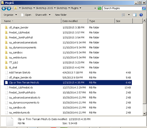
Figure 4-54 The Plug-ins folder on a PC, located in the program files, shows all installed extensions.
Pacman Ghost Ornament Project
This project uses the Outer Shell and Intersection solid tools and the s4u Face Maker extension to make the Pacman ghost ornament in Figure 4-55. We’ll draw it large and scale it down when finished.

Figure 4-55 A Pacman ghost ornament.
1. Model and group a block to draw on (Figure 4-56). Click the Rectangle tool on the workspace, type 8’,8’, and then push/pull it up 16’. Group it and click the Front View icon.
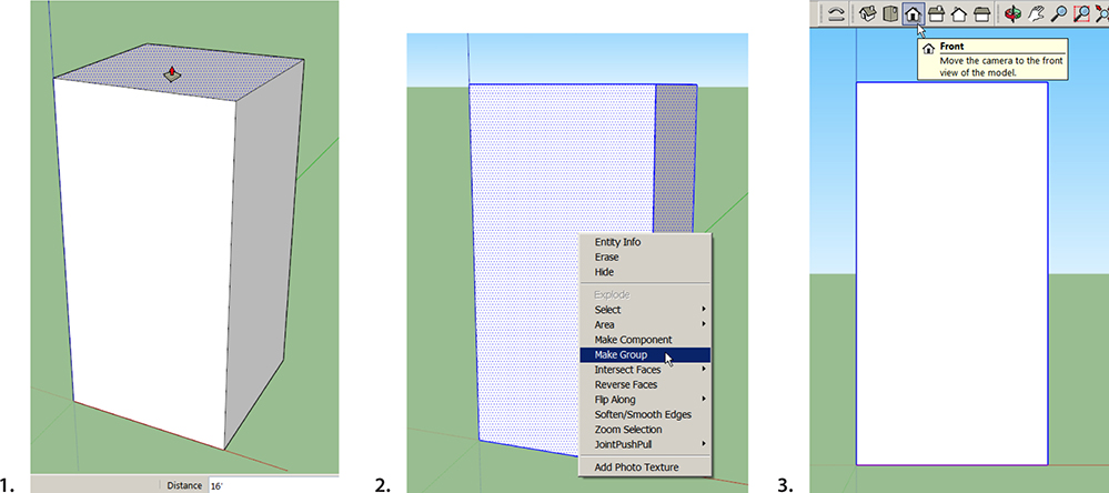
Figure 4-56 Model and group a block.
2. Draw the ruffle (Figures 4-57 and 4-58). Click on the Two Point Arc tool, click the endpoints 1’ apart, and then pull the bulge down until the Half Circle inference appears. Click to place. Make a second arc the same size in the opposite direction. Group them together.
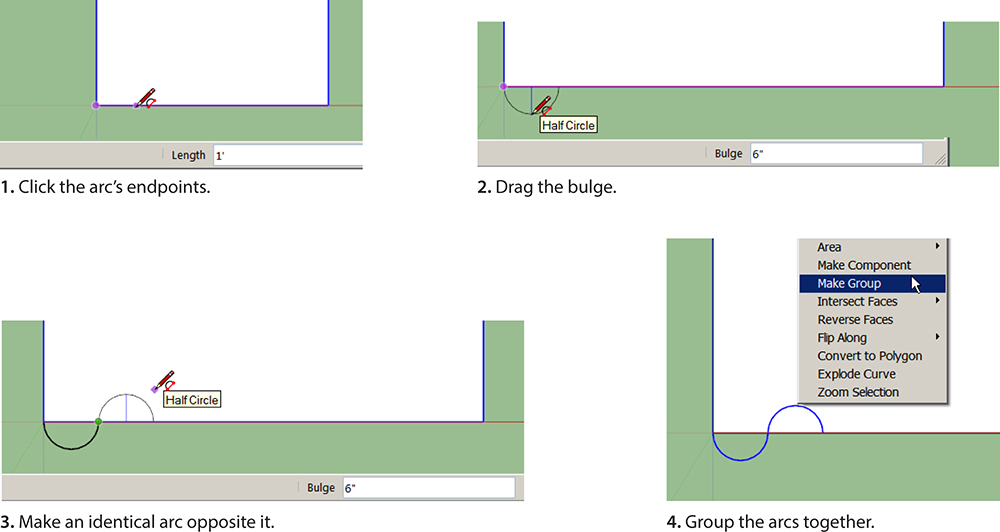
Figure 4-57 Draw the first two arcs of the ruffle, and group them together.

Figure 4-58 Make multiple, equally spaced copies of the grouped arcs.
Click on Move and then press the CTRL key to signify multiple copies (plus and minus signs will appear near the cursor). Drag a copy to the opposite end, and click. Then immediately type /3. Two more copies will appear, equally spaced between the first and last.
3. Make the ghost’s sides (Figure 4-59). First make the ruffle symmetrical by deleting the extra arc on the right (open its group editing box to do this). Then draw vertical lines from the arcs’ endpoints to the top of the block.
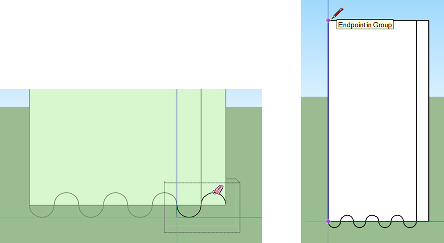
Figure 4-59 Delete the extra arc and draw the ghost’s sides.
4. Draw the ghost’s head (Figure 4-60). Use the Two Point Arc to draw a half-circle, and then trim the sides as needed. You can use the Eraser, but SketchUp 2015 lets you trim it with the Two Point Arc, too. Doubleclick on the extra part of the line as soon as you finish drawing the arc, right-click, and choose Erase. Then erase the block behind it, and explode the ruffle groups at the bottom (Figure 4-61). You’ll be left with an outline. If there are some lines and planes inside it, erase them, too.

Figure 4-60 Draw the ghost’s head.

Figure 4-61 Explode the ruffle groups.
5. Fill the outline with a face (Figure 4-62). Turn on the s4u Make Face tool by clicking on it at Views > Toolbars. Then select the outline, and click the tool. If the outline is coplanar (as it should be because you drew it all on the block and watched for On Face extensions, right?), a face will form.

Figure 4-62 Fill the outline with the s4u Make Face extension.
6. Give the face volume (Figure 4-63). Push/pull it forward 4’. Click the Offset tool on the perimeter, and drag a 3’ border. Push/pull the border 2’ forward. Then group it. Make sure that its Entity Info box lists it as a Solid Group.
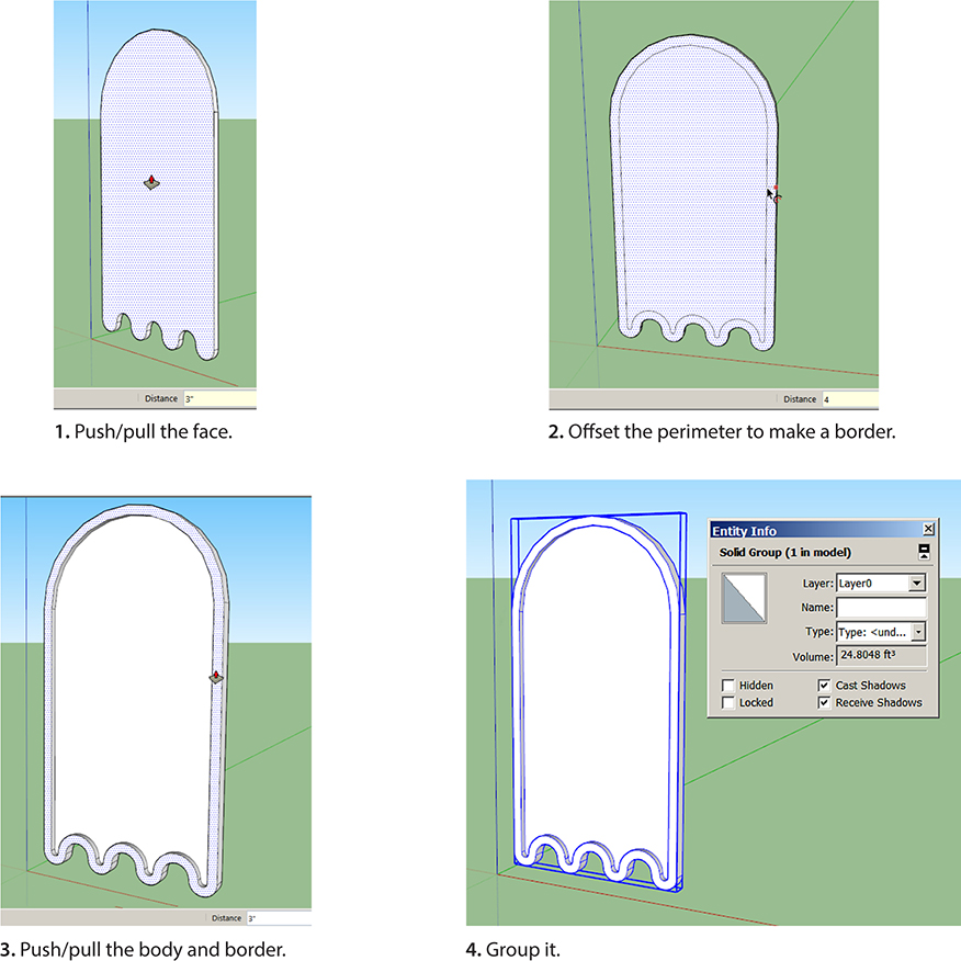
Figure 4-63 Create a ghost from the outline.
7. Model the eyes (Figure 4-64). Draw a circle, push/pull it forward, and group it (verify that it’s a solid group through the Entity Info box). Cut a moon shape into it as shown in Figure 4-64. Again, verify that it’s a solid group. Then copy it with Move and Ctrl (Figure 4-65).
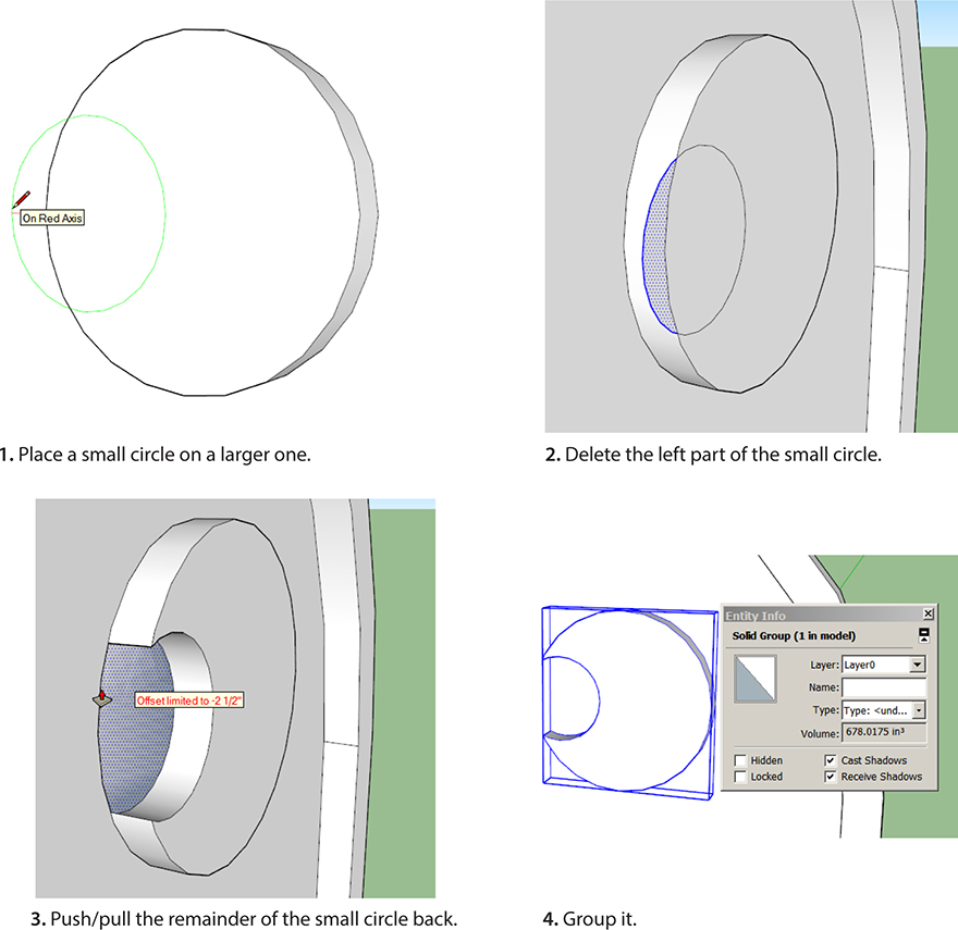
Figure 4-64 Model an eye.
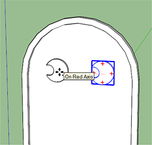
Figure 4-65 Copy the eye.
8. Weld the body and eyes together (Figure 4-66). Right now they’re three separate groups and have to be selected together to move together. We’ll use the Outer Shell tool to weld them together. Click on it, and then click on the body and one eye. Then click on the body and the other eye. All three should now highlight when you click any one of them and can be moved together. Welding them together is essential to making the ornament 3D-printable.

Figure 4-66 Use the Outer Shell tool to weld the three groups together.
9. Model a top ring (Figure 4-67). Draw two concentric circles, delete the center, move them to the ornament’s front edge, and push/pull them. Click the Push/Pull tool onto the ornament’s back edge to make the ring precisely the ornament’s width. Group it and verify that it’s a solid group. Then push the ring down into the body. Hold the keyboard’s DOWN ARROW to lock the ring along the blue axis if you’re having trouble moving it straight down.
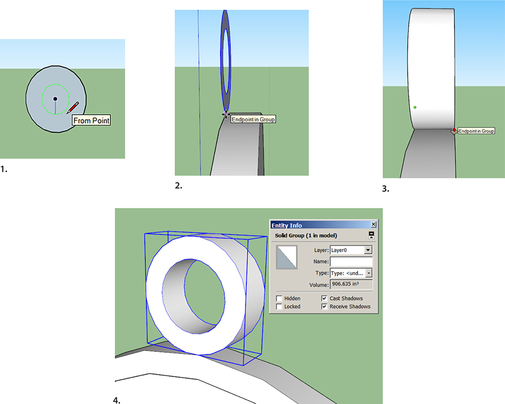
Figure 4-67 Model a top ring.
10. Delete the overlap inside the ring (Figure 4-68). Click on the Trim tool, click on the ring, and then click on the body. Next, click open the body’s group editing box and delete the overlap inside the ring.
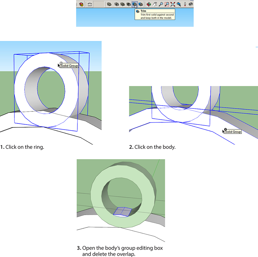
Figure 4-68 Trim the overlap inside the ring with the Trim solid tool.
11. Weld the ring and the body together (Figure 4-69). Click on Outer Shell, click on the ring and then click on the body. When finished, the ornament should highlight as one solid piece when you click anywhere on it.

Figure 4-69 Weld the ring and body together with the Outer Shell tool.
Finally, scale the ornament by clicking the Tape Measure onto opposite ends and typing whatever size you want.
AutoCAD Floor Plan Project
This is for you AutoCAD users! Pro can import a .dwg file. It imports as SketchUp geometry. In this project we’ll import and model the floor plan in Figure 4-70.
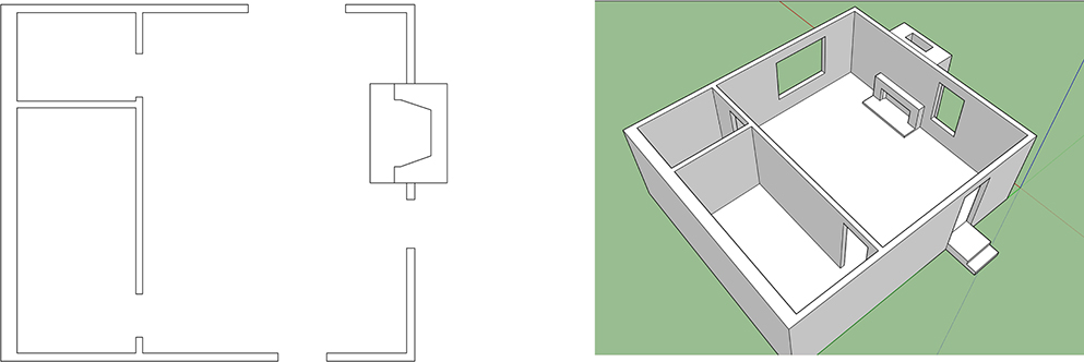
Figure 4-70 An AutoCAD floor plan and the SketchUp model made from it.
1. Import the AutoCAD file (Figure 4-71). Click File > Import, and locate it. Make sure that AutoCAD Files is visible in the Files of Type field at the bottom. Then click Options, and check the two upper boxes. The top two boxes tell SketchUp to treat the AutoCAD file like a SketchUp file. Set the Units field to the AutoCAD plan’s units. For example, if the plan’s units are feet, set it to feet. This is important! If the AutoCAD plan’s scale and this box’s scale are different, scaling the plan after import will be difficult. If you uncheck the Preserve Drawing Origin box, SketchUp can place the imported AutoCAD plan at the origin. If it imports far from the origin, clipping may occur, a glitch that causes part of the plan to disappear.
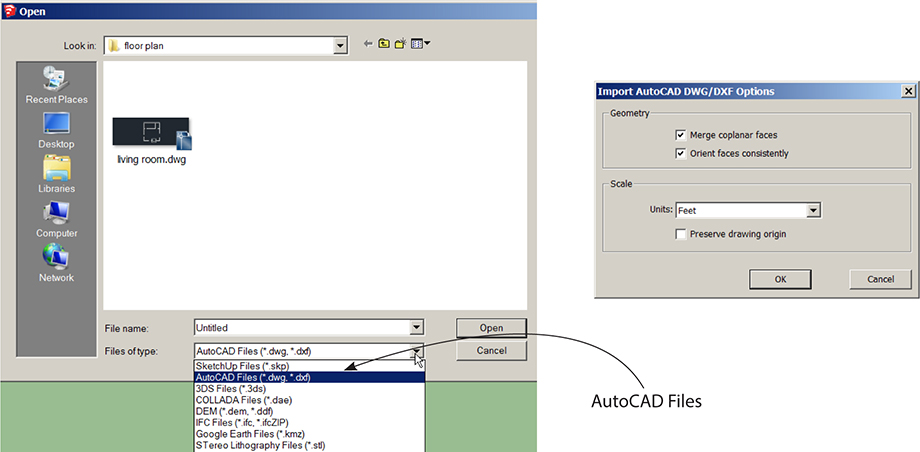
Figure 4-71 Navigate to the AutoCAD file and check the appropriate boxes.
AutoCAD software doesn’t need to be installed on your computer, but a .dwg file needs some preparation before import to make it easy to model. This is optimally done within AutoCAD. When importing your own files you may want to:
■ Copy and paste the plan into a new AutoCAD file to prevent stale metadata importing into SketchUp. Then move the plan to the origin.
■ Run the Purge and Audit commands to clean up any old data that did enter the new file.
■ Ensure that lines that are supposed to be connected at endpoints are indeed connected.
■ Run the Units command so that you know what the units are. Scale the file to 1:1 if it isn’t already scaled.
■ Delete unused layers. SketchUp automatically discards anything in the imported .dwg file that has no 3D relevance, such as text, dimensions, hatch lines, and title blocks. However, it doesn’t discard the layers they’re on.
■ Explode all polylines, arcs, and filleted lines.
■ Erase any construction entities, such as points created where lines were divided. They import as random bits of geometry.
■ Remove all textures, x-referenced and imported files, colors, and dynamic blocks.
■ Ensure that the file is smaller than 15 MB because larger ones might not import.
Click Open to import the .dwg file. A box will briefly appear that lists the specific data imported, and then the AutoCAD file will appear. It’s now SketchUp geometry.
If your plan imports as a group, explode it (select, right-click, choose Explode). One explosion shouldn’t affect imported blocks, which enter SketchUp as components. However, you might find that some blocks (now components) behave oddly when panning and orbiting. Fix by exploding and remaking them as components again.
2. Make faces (Figure 4-72). The plan imports as lines, with no faces between them. Drag the Rectangle tool over it (click on opposite corners) to cover the whole plan with a face. The existing lines will break it into multiple faces.
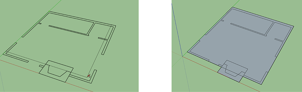
Figure 4-72 Drag a rectangle over the plan to make faces.
3. Scale the plan (Figure 4-73). Click the Tape Measure on opposite ends of an item with a known dimension. Here I’ve clicked on a door opening. After clicking on the second endpoint, immediately type the desired length. A note will appear asking if you want to rescale the model. Click Yes, and the model will scale proportionately to the size of the item you scaled. Note that the plan here has the front (white) side down, so select, right-click, and choose Reverse Faces to face it up.

Figure 4-73 Scale the model by scaling an item with a known dimension. Reverse faces, if needed, so that the front (white) side shows up.
4. Model the walls and floors (Figure 4-74). Push/pull one of the wall sections up, type 9’, and press ENTER. Then inference match the rest of the walls to that section by pushing/pulling them up, hovering the cursor over the first section, and releasing it. Push/pull up the floor in one room 6" and inference-match the other floors to it.

Figure 4-74 Model the walls by pushing/pulling the first section up and inference matching the rest to it. Then do the same to the floors.
5. Finish the window and door openings. When you pull up walls with windows marked in them, they’ll be unfinished at the top (Figure 4-75). Draw lines across the top, mark the head height with the Tape Measure, and trace over the guideline created (Figure 4-76). Do this on both sides of the wall.
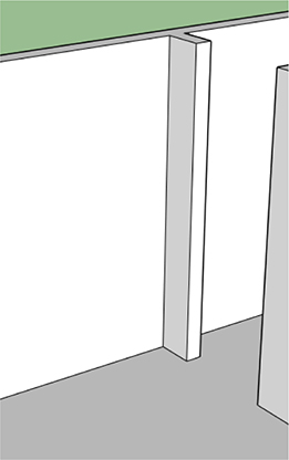
Figure 4-75 After the walls are push/pulled up, openings will be unfinished at their tops.

Figure 4-76 Draw the top of openings with the Tape Measure and Pencil tools. Do this on both sides of the wall.
Faces will form when you draw new lines; just delete them (Figure 4-77). Eventually the openings should look like the ones in Figure 4-78. Note that there must be faces on the sides, too. If a face got deleted, undo and trace your steps to see what went wrong, and try another workflow (sequence of steps). Inside the house, delete all unnecessary lines (Figure 4-79).
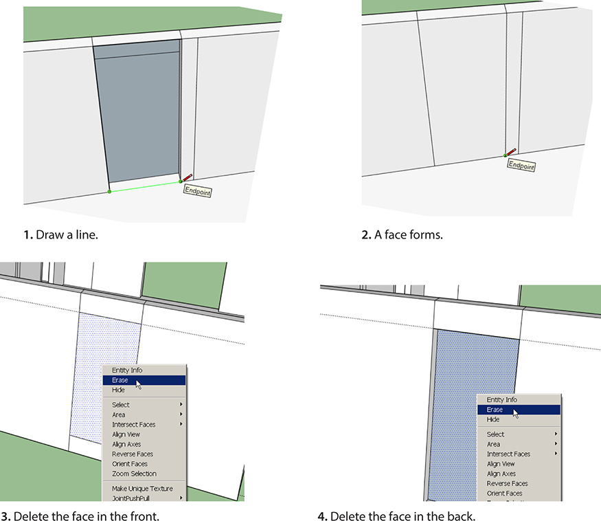
Figure 4-77 Delete the faces on both sides of the wall.

Figure 4-78 A finished opening, front and back.
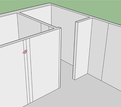
Figure 4-79 Delete all unnecessary lines inside the house.
6. Draw stairs. Because we push/pulled the floor up, the inside isn’t level with the outside. Fix that with stairs as shown in Figure 4-80.
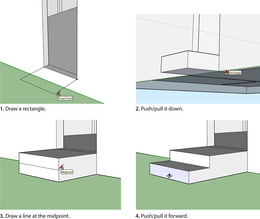
Figure 4-80 Model some stairs in front of the door.
7. Model the fireplace (Figure 4-81). Do this by pushing/pulling its outline up. Or import and scale one from the Warehouse.

Figure 4-81 Model the fireplace. Here one side is being inference matched to the other.
Layers
Layers are sheets attached to a model. You can move groups and components onto these sheets. All models start with Layer 0, but you can add as many as you want. Go to Window > Layers, and click the plus sign (Figure 4-82) to create and name a new layer. Then select geometry, make it a group or component (Figure 4-83), right-click it to access the Entity Info box, and click on the box’s drop-down arrow to select a specific layer. This puts the selected group or component on that layer. You can turn layers off, which is useful when working on parts obscured by other parts. To delete a layer, right-click and choose Delete. Layer 0 cannot be deleted.

Figure 4-82 At Window > Layers, click the plus sign to make and name new layers.
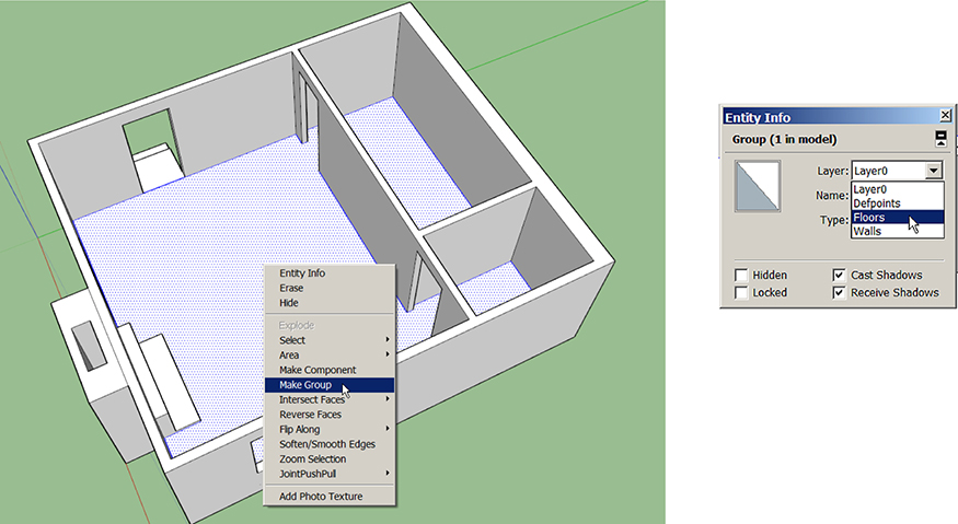
Figure 4-83 Group geometry and move it to different layers via its Entity Info box.
All loose geometry should be on Layer 0. Don’t put loose geometry on any other layer because it will be easy to lose. Make a layer current, meaning that all new construction will go on it, by clicking its radio button.
Summary
In this chapter we installed and used extensions, which are tools that perform actions the native ones can’t. We included content from the Thingiverse in our modeling, discussed solid geometry, used solid tools, and imported an AutoCAD file. In Chapter 5 we’ll make some of our models 3D-printable.
Resources
■ Creative Commons:
http://creativecommons.org/
Information on public copyright licenses.
■ Extension Warehouse:
https://extensions.sketchup.com/
Direct Web URL
■ Terrain Model Video:
https://youtu.be/y22kYRnsuus
Repositories of Free and Pay Models
■ Thingiverse: http://www.thingiverse.com/
■ YouMagine: https://www.youmagine.com/
■ GrabCad: https://grabcad.com/
■ Formfonts: http://www.formfonts.com/
■ Pinshape: https://pinshape.com/
Student Pro Licenses
■ http://www.creationengine.com/html/m.lasso?m=GG&gclid=CJ7h9eOO98MCFYQ8aQodcZcAag