
CHAPTER 7
CNC Fabrication with Pro, 123D Make, and Cut2D
IN THIS CHAPTER we’ll turn SketchUp models into scaled 2D files that can be fabricated on a computer numerical control (CNC) router. This manufacturing method is common for making crafts, terrain models, and furniture. It’s a more mature technology than 3D printing, and the post-processing work is often easier than cleaning a print. CNC machines operate with computer-aided manufacturing (CAM) software.
Specifically, we’ll slice up the terrain model from Chapter 4 with a CAM program called Autodesk 123D Make and export it into a CAM-appropriate format. We’ll use SketchUp Pro to export the Chapter 3 nameplate into scaled .pdf and .dxf formats and then import the .pdf file into a CAM program called Vetric Cut2D. In the process, we’ll learn about CAM software, the files it needs, how to generate them, and a bit about the machines themselves.
What’s a Router?
A router is a machine that cuts or carves sheets of wood, plastic, glass, nonferrous metal, foam, and wax (Figure 7-1). Routers that are larger and can cut harder metals are mills. Both routers and mills consist of a metal frame that holds a gantry, rotary cutter (Figure 7-2), and cutting bed. A “sacrificial sheet” is placed under the cutting sheet to protect the bed.

Figure 7-1 A “Joe’s CNC” kit machine attached to a PC. (Hammerspace, Kansas City, MO)

Figure 7-2 End and ball mills come in thousands of shapes and sizes.
Routers use end mills and ball mills (Figure 7-2). These cut side to side and move along the x, y, and z axes as opposed to drills, which just cut up and down. Hence, they can carve as well as cut (Figure 7-3). A CNC router holds and cuts the material via inputted computer code as opposed to an operator manually holding and manipulating the material against a cutter.

Figure 7-3 CNC machines cut the ornaments (left) and carved the Mayan calendar (right).
Nonferrous metals are the “softer” metals such as brass and aluminum. Foam, wax, and medium-density fiberboard (MDF) are materials used to make patterns and test designs before committing to more expensive materials.
CNC fabrication is a subtractive process, meaning that material is removed to make an object. This process generates a lot of chips. Another CNC cutting tool is a laser, a hot beam of light that cuts a material cleanly (Figure 7-4). Depending on the project, you may want to use a router or a laser.

Figure 7-4 Lasers cut a material cleanly. The lower-right corner was lasered and sand blasted to remove the burn color.
Computer-Aided Manufacturing Software
Computer-aided manufacturing (CAM) software creates the files that run a CNC machine. Expensive commercial machines like those made by Haas have built-in computers that use proprietary software. Kit and lower-cost machines attach to a PC through a USB port and run either software specifically written for them or generic cross-platform software.
CAM programs vary greatly in features, cost, and complexity. Some have rudimentary modeling, drawing, and editing capabilities; create cutting patterns; and generate G-code, which is the language machines understand (Figure 7-5). Some have one or two of those functions, and some just read G-code. Some CAM programs read 3D .stl files, but most require scaled 2D vector files in a .pdf, .dxf, or .eps format. Popular CAM programs include Fusion 360 and 123D Make (Autodesk), V-Carve Pro and Cut 2D (Vetric), Mastercam (CNC Software), Mach 3 (Artsoft), and Cambam. Good, free CAM software is not plentiful like 3D printing software.
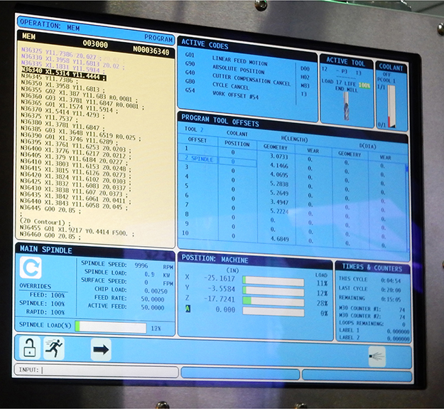
Figure 7-5 G-code displayed on the built-in computer of a Haas CNC mill.
The Process for CNCing with SketchUp
Here’s an overview of the process for CNCing with SketchUp:
1. Model the project. Run Solid Inspector2, CleanUp3, SU Solid, and/or any other tool you learned about in Chapter 5 to remove extra geometry and optimize the model as much as possible. A SketchUp model doesn’t have to be a solid group or component to import into a CAM program, but if it has a lot of defects, such as nonmanifold edges or holes, it may import with errors or be difficult to work with (Figure 7-6).

Figure 7-6 The dog tag (left) was fixed with Solid Inspector2 and imported successfully into 123D Make. The unfixed tag (right) imported with parts missing.
2. Export the SketchUp model as an .stl, .pdf, or .dxf file depending on the requirements of the CNC program you plan to use it with. The .stl extension in the Extension Warehouse works with both Make and Pro. However, only Pro exports a file as a .pdf or .dxf file. Figure 7-7 shows Pro’s export choices.

Figure 7-7 Exporting a model as a .pdf file in SketchUp Pro.
SketchUp Make users can obtain .pdf and .dxf files with a bit more work. Free and low-cost .pdf writers exist; two popular ones are at cutepdf.com and pdf995.com. Once one is installed, click on File > Print, and print to the .pdf writer instead of to the paper printer. It will generate a .pdf file with a default name that’s the same as the model name. Be aware that all .pdf programs do not export vector files. Pdf files can also be raster (pixel) files, and these are not compatible with CAM software. A way to tell a vector from a raster file is by opening it with Adobe Reader and clicking on it. Raster images will highlight as when clicked on, and their lines will look jagged when enlarged greater than 400 percent.
A way to get a .dxf file from SketchUp Make is to export the model as a .dae file, import it into Blender (a free modeling program at blender.org), and export it from Blender as a .dxf file. A .dxf format is always a vector file.
3. Import the .stl, .pdf, or .dxf file into a CAM program that does what you need, such as generate pattern pieces on sheets and/or generate G-code files.
4. Import the G-code files into a CNC machine that reads and cuts them out, or upload them to a service bureau such as ponoko.com or shapeways.com.
Architectural Terrain Model Project

Let’s turn the Chapter 5 terrain model into pattern pieces. First, export it from SketchUp as a .stl file (Figure 7-8). Then download Autodesk 123D Make at 123dapp.com/make, and launch it. Figure 7-9 shows the 123D Make interface.

Figure 7-8 Export the SketchUp terrain model as an .stl file.

Figure 7-9 The 123D Make interface.
There’s a workspace, Menu bar at the top, and vertical panel on the left. The Menu bar has a drop-down arrow that accesses a submenu (Figure 7-10), and next to it are Undo and Redo arrows.

Figure 7-10 Click the drop-down arrow in the Menu bar to see this submenu.
The submenu includes these functions:
■ New. This closes the current file and makes the Import button appear.
■ Open Example Shapes. This brings up choices of premade files with which to experiment.
■ Open. This brings up a navigation browser window from which you can open an existing 123D Make project.
■ Export Mesh. This turns the 123D Make file into an .stl or .obj file.
Click the Import button to bring up a navigation browser. Then navigate to and import the terrain model .stl file (Figure 7-11). Some new items now appear: a terrain .stl button (click it to close the file and open a navigation browser), manufacturing settings, a View Cube, and a navigation panel.

Figure 7-11 Import the terrain model .stl file.
Navigating the 123D Make Interface
You can move around the interface three ways: with the View Cube, the mouse, and the Navigation bar.
■ View Cube. This shows the model’s orientation on the workspace. Click the mouse on it and drag to rotate. The model will rotate with it. Click on the View Cube’s sides to see the model as a top, front, or side view. Hover the mouse over the View Cube to make a house icon appear. Clicking on that house returns the model to the default position and perspective view.
■ Mouse. Right-click anywhere on the screen, and drag the cursor to tumble the model (move it at any angle around the workspace). Press the scroll wheel down to drag the cursor, which pans, or slides, the model around the workspace. Roll the scroll wheel up and down to zoom in and out.
■ Navigation panel. Click on the first four icons to tumble, pan, zoom, and fit (fit fills the screen with the model). Click on the last icon to toggle between perspective and paraline views.
Choose the Manufacturing Settings and Object Size
We need to select the sheet size from which the project will be cut. In the Manufacturing Settings box, click the drop-down menu, and scroll through the choices (Figure 7-12).

Figure 7-12 Click the pencil to access the Manufacturing Settings options.
Click on the pencil for a screen that shows all settings choices (Figure 7-13). It has graphics at the bottom for adding your own presets, which is handy for non-standard materials. Click the plus sign to add a new preset. To make a variation of a preset, click that preset to highlight it, and then click the double plus sign to make a duplicate. Enter the new settings. To delete a preset, highlight it, and click the minus sign.

Figure 7-13 Add your own presets in the settings choices window.
Now select the physical size in the Object Size panel (Figure 7-14). Choose its units, and adjust the height, width, and length, if needed. Clicking the Uniform Scale button scales the file in all directions. When it’s unclicked, you can scale the model differently along the three axes. Clicking the Original Size button reverts the file back to its size at import. The larger the file, the more slices will be generated, and the more sheets you’ll need.

Figure 7-14 Click the drop-down arrow to select a construction technique.
Construction Techniques
At the bottom of the panel is the Construction Technique box. Click the drop-down arrow to select how to fabricate the model.
There are six techniques: Stacked Slices, Interlocked Slices, Curve, Radial Slices, Folded Panels, and 3D Slices. The model will update to reflect each technique you choose, with accompanying 2D graphics of slices laid out on sheets. All construction techniques have options with which you can finesse the model. Most overlap, but each has at least one option that is unique to it. As you finesse the options, the slices automatically update. Know that slices and parts are not synonymous. A slice can consist of multiple parts.
The 123D Make Process Using Stacked Slices
We’ll go through the whole 123D Make process on the terrain model now, from choosing the technique to printing a .pdf file.
1. Click on the Stacked Slices technique. This makes cross-sectional slices for gluing and stacking on top of each other (Figure 7-15), which is how physical terrain models are made. Note the graphics under the Cut Layout tab.

Figure 7-15 The Stacked Slices option turns the model into cross-sectional slices.
The Dowels option (Figure 7-16) creates pegs that help to align and hold the slices together. You can choose their size, location, and shape. Move a dowel by highlighting and dragging it; remove it by highlighting and hitting the DELETE key. Click on the Slice Direction icon to make a blue handle appear that you can drag to change the slice direction (Figure 7-17). Blue parts are unconnected to others. Red parts are too large for the cutting sheet (Figure 7-18). Click on the Model Issues tab (Figure 7-19) for a list of problems. Note that when selecting options, you need to click on the icon; nothing happens if you simply click the larger button the icon is on.

Figure 7-16 Adjust dowel locations by dragging them. Adjust their size and shape via the menu.

Figure 7-17 Change the slice direction by dragging the blue handle.

Figure 7-18 Red parts are too large for the cutting sheet.

Figure 7-19 Click the Model Issues tab to see any problems. None are shown here.
Even if everything looks fine, problems may appear when you export the model to a file. If this happens, click on the Modify Form icon to bring up three buttons at the bottom of the screen: Hollow, Thicken, and Shrinkwrap (Figure 7-20). Hollow shells out the model, reducing the amount of material needed to build it. Thicken widens cutouts that are too thin to print. Shrinkwrap approximates and smoothes details that are too fine to cut out and closes holes. Select one, adjust its slider, and click Done.

Figure 7-20 The Modify Form icon accesses Hollow, Thicken, and Shrinkwrap options at the bottom of the screen.
Be aware that Shrinkwrap affects the whole model, not just a problem slice. So the end product may change the model’s appearance. Additionally, know a machine cutter’s limitations; for example, a router can’t make square corners. Appropriate clearances, which are spaces for parts to connect, are also needed.
2. Click on the Assembly Steps icon and choose the material (Figure 7-21). Drag the mouse along the slider at the bottom of the screen to watch an animation that puts the parts together (Figure 7-22). To view an assembly sheet, click on it in the Assembly Reference panel (Figure 7-23). Move the sheet by clicking and dragging; scroll the mouse wheel to zoom in on a part; click the X in the upper-right corner to return to the model.

Figure 7-21 Click on Assembly Steps to choose the material.

Figure 7-22 Move the slider to view an animation.

Figure 7-23 View an assembly sheet by clicking on its graphic.
Study the graphics in the Cut Layout tab (Figure 7-24) because they show how many sheets of material are needed, how many slices and parts, and where problems are. Hyphenated labels, such as Z-3-2, describe the part’s axis (Z), the slice number (3), and the part number (2). Blue outlines are the model’s outside edge, green outlines are cuts inside the model for hollows, yellow outlines are scored guides for placing parts during assembly, and red parts have too many errors to be built.
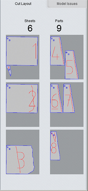
Figure 7-24 The graphics in the Cut Layout tab show the material sheets.
The parts are arranged to use as much of each sheet as possible, and all are oriented in the same direction. Currently, there is no other way to arrange them. If you want to change the arrangement—perhaps a wood grain faces the wrong direction—import the file into another vector program such as Inkscape (free at inkscape.org) or Adobe Illustrator, and change it there.
3. Export the file. Click on the Get Plans icon, choose the format (.eps, .pdf, or .dxf) and units, and click Export (Figure 7-25). The file will be exported into a format that is ready for postprocessing (G-code generation) in any CNC machine. The .eps option creates a zip folder with separate files for each sheet. It and .dxf files put text on one layer and profiles on another, which is useful when importing into another CAM program for CNC cutting.
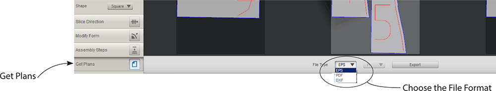
Figure 7-25 Click on the Get Plans icon, choose an .eps, .pdf., or .dxf file format, and export it.
The .pdf option creates one file that puts all the slices on separate pages (Figure 7-26).

Figure 7-26 The .pdf export screen and the resulting file.
Other 123D Make Construction Techniques
You probably noticed that the Construction Technique field has multiple options. Click the head in the Open Example Shapes submenu (Figure 7-27), and let’s apply the other techniques to it (Figure 7-28).

Figure 7-27 Click the head in the Open Example Shapes submenu.

Figure 7-28 Construction Technique options applied to the example head.
■ Interlocked Slices. This slices the model into two stacks of slotted parts that lock together in a grid. It uses less material than the Stacked Slices technique.
■ Curve. This cuts slices perpendicular to a curve.
■ Radial Slices. This creates radiating slices from a central point. It works best on round, symmetrical models.
■ Folded Panels. This turns the model into 2D segments, or panels, of triangular meshes that are folded multiple times and held together with tabs (Figure 7-29).

Figure 7-29 A folded panels art piece by dtworkshop.com.
■ 3D. This slices the model and follows its form as opposed to merely stepping them to create a form, as with the Stacked Slices technique.
Figure 7-30 shows the fingernail from Chapter 5 with the Radial Slices and Interlocked Slices techniques. Both show red and blue parts. You may be able to fix them by finessing the technique’s options. However, every technique won’t work on every model.

Figure 7-30 The Radial Slices (left) and Interlocked Slices (right) techniques on the fingernail from Chapter 5.
Exporting a .pdf File from SketchUp
We can get scaled orthographic (2D) views directly from SketchUp, and here’s how. First, change the default view from perspective to paraline by clicking on Camera > Parallel Projection. Then open the Views toolbar. Combine the Parallel Projection setting with a standard view (Figure 7-31) to generate a 2D drawing. Because standard views are aligned along the red, green, and blue axes, the model must be aligned with those axes, too.

Figure 7-31 Combine Parallel Projection with the Views icons to generate orthographic views.
Change the workspace so that the background will print solid white (Figure 7-32). Go to Window > Styles to bring up the Default Styles dialog box. Under the Select tab, the Default collection folder should be visible in the text field; if it isn’t, scroll to it. Click on the Construction Documentation style. The background will turn completely white. Then click on the View menu and uncheck Axes to remove the axes from the display (Figure 7-33).

Figure 7-32 Change the style to Construction Documentation.

Figure 7-33 Turn off the axes display.
Name Plate Project
Let’s export the name plate from Chapter 3 as a scaled, orthographic .pdf file using the .pdf writer that comes with SketchUp Pro. As mentioned earlier in this chapter, you can download and install a free .pdf writer to work with SketchUp Make. Just be aware that it may not have the same features as SketchUp Pro’s .pdf writer and that you have to ensure that it exports vector files.
Group and Arrange the Parts
We’re going to cut the letters and base separately. So group them separately to make them easier to lay out (Figure 7-34). Ideally, each will be a solid group; if not, run tools on them to make them so, or to clean them up as much as possible.

Figure 7-34 Group the name and base separately.
Lay the two groups flat and click on the Top View icon (Figure 7-35). We only need this view because depth information is entered manually into a CAM program.

Figure 7-35 Lay the two groups flat, and generate a top view with Camera > Parallel Projection and the Top View icon.
Print Preview
Click Print Preview, and scroll to Adobe PDF in the first text screen to see what you’re about to print (Figure 7-36). Here are the most relevant options:
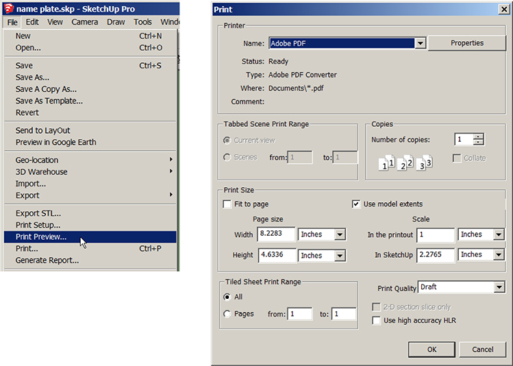
Figure 7-36 Click Print Preview, and scroll to Adobe PDF in the Name field to see what you’re about to print.
■ Fit to Page. Deselect this. It forces the print output to fit in a single page with no regard to scale. It also disables the Page Size fields and the Tiled Sheet Print Range options.
■ Use Model Extents. Check this box to reduce the empty space around the model, thus reducing the number of tiled pages when printing large models. It doesn’t affect the print’s scale, just the overall size. This may help you to fit a scaled print onto a single page or reduce the number of pages the print requires. Figure 7-37 shows a .pdf made with Model Extents off, not a result we want.

Figure 7-37 With Model Extents off, the model tiled across two pages. This is not a result we want.
You can print any size model. Small ones can be printed full scale and take up one page; larger ones need to be scaled down and will span multiple pages, as what 123D Make generated. However, printing small models may result in a print that spans more pages than is necessary. Resolve this by manually resizing the SketchUp window to minimize the empty space around the model. Deselect Model Extents, click the Zoom Extents icon (Figure 7-38) to confirm the model is centered, and then drag a corner of the SketchUp window to resize it, cropping as much empty space around the model as possible (Figure 7-39). You also can orient the page in portrait or landscape style to suit the dimensions of the model (discussed later in this chapter). Note how the Page Size and Tiled Sheet Print Range fields change as you toggle Use Model Extents on and off.
Figure 7-38 The Zoom Extents icon fills the screen with the model and centers it.

Figure 7-39 Drag a corner of the SketchUp window to crop unnecessary space.
■ Scale. This is the ratio of printed size to actual size. Look at the Scale fields (Figure 7-40). To make the print full size, type the following: In the Printout, type 1, and select any unit from the adjacent field’s drop-down menu. In SketchUp, type 1, and select the same unit from the adjacent field’s dropdown menu. To scale the print at 1/4″ = 1’0″, type the following: In the Printout, type 1/4 or .25, and choose Inches. In SketchUp, type 1 and choose Feet.

Figure 7-40 Type as shown in the text fields to print the model full scale (left) or ¼″ = 1′0″ (right).
In both cases, make sure that Fit to Print is deselected, that Camera > Parallel Projection has been clicked, and that one of the Standard Views icons has been clicked. Otherwise, the scale fields will be gray.
■ Page Size. These fields display the overall size of the printing, not the size of the paper. When you type numbers into the Scale fields, SketchUp calculates the overall dimensions of the print and displays the resulting width and height in the Page Size fields. Don’t type numbers into the Page Size fields when printing to scale. Look at the width and height dimensions displayed, and judge whether the printing will fit within the paper’s printable area. Be aware that the Page Size width and height fields don’t update automatically when you type numbers in the Scale fields. Toggle the Use Model Extents option to refresh the Page Size fields. Note the effect Use Model Extents has on the print’s overall width and height.
■ Tiled Sheet Print Range. When the overall size of the printing is larger than the printable area of a single page, SketchUp spans, or tiles, the printing across multiple pages. You can print all the pages, a single page, or a range of pages. The default print range is All, and the From/To fields show the total number of pages. The Tiled Sheet Print Range fields don’t update automatically when you type numbers in the Scale fields. Refresh them by toggling the Use Model Extents option.
■ Use High Accuracy HLR. Check this box to create a vector file. Otherwise, SketchUp prints a raster file. Vector files only show colors, not textures. Textures and other images appear as shades. If you want the textures as part of the .pdf file, deselect this box.
Now click the Properties button to bring up another window (Figure 7-41). At the Adobe Pdf Settings tab, you can change the .pdf paper size, and at the Layout tab, you can orient the print as portrait or landscape (Figure 7-42). The Layout and Paper/Quality tabs both have advanced settings that you might want to explore for your particular project.

Figure 7-41 The Properties button brings up this window.

Figure 7-42 From the Layout tab, orient the print as portrait or landscape style.
Print the .pdf File
If you don’t like the Print Preview image, click Close. Adjust the settings, and view it again. If you like it, click Print. The Print dialog box will open. Click OK. Figure 7-43 shows a .pdf file of the model’s top view. It is a scaled orthographic drawing.

Figure 7-43 The .pdf file shows the model’s top view.
Exporting a .dxf File

At File > Export > 2D Graphic, SketchUp Pro has a .dxf option (Figure 7-44). This creates a vector file that can be imported into many CAM and Autodesk programs as well. As an aside, if you plan to give the file to a third party to fabricate, the .dxf format is often preferred because the machine operator knows it’s a vector file instead of a possible raster file.

Figure 7-44 The model can be exported as a .dxf file. Click on the Options button for settings.
Make sure that Camera > Parallel Projection and one of the Standard Views icons are checked. Then click on the Options button. Most of these settings apply only if you want to export your SketchUp model to an Autodesk program for further development. At the end of this chapter is a link that explains them. Following are the ones relevant for CNC work:
■ Drawing Scale and Size. This contains scaling options:
■ Full Scale (1:1) makes the drawing true-life size.
■ In Drawing/In Model scales the drawing. For example, to scale the drawing at 1/4″ = 1″, type the following: In Model, type 1″. In Drawing, type 4′.
■ Width/Height. Enter a custom page size for your file.
■ Profile Lines. Check this to export any profile lines.
■ Section Lines. This has options for exporting section lines.
Figure 7-45 shows the .dxf file open in AutoCAD. If you don’t have an Autodesk program on your computer with which to see it, you can download a free .dwg viewer. A link is given at the end of this chapter.

Figure 7-45 The exported .dxf file open in AutoCAD.
G-Code
After creating a .pdf or .dxf vector file, the next step is to import it into a CAM program that generates G-code. G-code, also called post-processing, tells the router the tool path, or how to move to make the part. It also tells the router how fast to move, what kind of stock it’s cutting, the stock’s thickness, and the finish type (such as rough or smooth). All CNC machines are built and configured differently, so their G-code is slightly different.
Generating G-code requires a working knowledge of speeds, feed rates, tool paths, cutter types, stepovers, the work-plane coordinate system, origin location, collision checks, tabs, 2 1/2D versus 3D, and properties of stock materials. This is beyond the scope of this book. There are busy online forums devoted to CNCing and CAM programs, and some are listed at the end of this chapter. However, we’ll take a look at what a .pdf file looks like in one program and discuss issues that may arise.
Prepare the SketchUp-Exported .pdf Inside Vetric Cut2D

Once you generate a .pdf or .dxf file, the next step is to import it into a CAM program that converts it to G-code. Let’s import the name plate .pdf into a popular program called Cut2D. We’re not going to go through this program’s steps. Rather, I want to point out issues to watch for that will apply to any program you import it into.
First, import the file, and enter the sheet material’s dimensions and location on the router bed (Figure 7-46).

Figure 7-46 Import the .pdf file.
A SketchUp-exported file almost always needs editing inside CAM software. Because of the nature of a 3D model and SketchUp, the imported file will almost never be machine-ready. For example, all shapes in a CNC file need to be closed polygons, but here we see that the base plate has a double line. In Chapter 3 we beveled it (Figure 7-47), and those double lines represent the bevel. But double lines make no sense to a router; the base must have just one line so that the router can tell which is outside and which is inside. So we need to delete the interior line, and can do so with Cut2D’s editing tools (Figure 7-48).

Figure 7-47 The base plate’s beveled edge.

Figure 7-48 The interior edges must be deleted.
Now look at the letters. Clicking on each one shows that they’re not closed polygons; rather, they’re made of multiple individual lines (Figure 7-49). This must be fixed, too. Additionally, SketchUp files often import with multiple lines stacked on top of each other. This will cause the router to repeat a cut in that location as many times as there are lines. So each line needs to be clicked on and deleted to ensure that there isn’t an identical line beneath it. Removing stacked lines can be done in the Cut2D software, but on a complex model it will take awhile to do. The i needed its top two pieces removed because Cut2D only has editing, not drawing, tools, and it would be difficult or impossible to turn all three into one closed polygon. Because of these kinds of issues, many Makers prefer to create their CNC designs in 2D drawing software instead of 3D software. Illustrator (Adobe), AutoCAD (Autodesk), Solidworks (Dassault), and Draw (Corel) are popular programs.

Figure 7-49 Each letter is composed of multiple lines. They must be edited to be closed polygons inside the CAM software.
Once all work on the file is completed, G-code is generated. The file is saved and then transferred to the computer on the CNC machine, where it is read and cut. Figure 7-50 shows Mach 3 software, a popular G-code reader, and a close-up of the name plate file. The stock material is clamped down to the bed, and cutting begins. Figure 7-51 shows the name plate being cut out of a piece of foam. Note the tab holding the cut-out piece to the stock piece. This is one of the features you program into G-code. Figure 7-52 shows all the cut-out pieces, including the tabs that held the letters to the foam.

Figure 7-50 The Cut2D file opened in Mach 3.

Figure 7-51 The CNC router reads the G-code and cuts the project.

Figure 7-52 The cut-out pieces.
The Right Tool for the Right Job
Figure 7-53 shows the CNC router cutting the project out of wood. However, it takes about four times as long to cut the name plate base on a CNC router than on a table saw (Figure 7-54). And while a decorative edge could be carved on the CNC router, a table router will do that job quicker, too (Figure 7-55). However, the letters are easiest and safest to cut out with the CNC router. Knowing which tools to use for a job is a large part of the job, too.

Figure 7-53 A CNC router cutting the base plate out of wood.

Figure 7-54 A table saw will do the job faster than a CNC router.

Figure 7-55 An ogee curve is cut on the name plate’s edges with a table router. A vacuum is hooked up to the router to remove wood chips. (Hammerspace, Kansas City, MO)
SketchUp LayOut

One more thing! If you want scaled, 2D, annotated construction documents of your model, SketchUp Pro’s LayOut feature will do the job. It downloads as a separate program when you install SketchUp. Export the SketchUp model directly to LayOut via the LayOut icon (Figure 7-56) and create viewports, each of which can display and scale a different view of the model (Figure 7-57). You can also dimension and annotate the views (Figure 7-58). The document can be exported as a .pdf, .dwg., or dxf file. A video showing how to use LayOut is at https://youtu.be/izk5eWuubFs.

Figure 7-56 Import the SketchUp model directly into LayOut with the LayOut icon.

Figure 7-57 Create viewports, choose views, and scale the views.

Figure 7-58 The final LayOut document.
Summary
In this chapter we learned how to turn a SketchUp model into a file for fabrication on a CNC router. We sliced a 3D .stl file into multiple 2D pattern pieces with Autodesk 123D Make. We generated scaled, orthographic .pdf and .dxf files with SketchUp Pro. We opened a SketchUp-exported .pdf file in Vetric Cut2D to work on the model further, then opened the G-code generated there in Mach 3 CAM software. We cut the pattern out in foam on a CNC router and looked at some manual tools that could be part of the workflow.
Resources
■ Video of the Terrain Model project:
https://www.youtube.com/watch?v=y22kYRnsuus
■ Video of the Nameplate under construction:
https://www.youtube.com/watch?v=XTxZsQFSzWs
■ Forum for CNC hobbyists and professionals:
http://cnczone.com
■ Forum for Vetric software users:
http://forum.vectric.com/
■ Autodesk CAM site:
http://cam.autodesk.com/
■ Service bureau for CNC projects:
http://ponoko.com
■ Interesting CNC projects: http://blog.ponoko.com/2012/01/11/ten-excellent-examples-of-cnc-routing/
■ Find CNC-related extensions in the Extension Warehouse: https://extensions.sketchup.com/
■ Explanation of .dxf export options:
http://help.sketchup.com/en/article/114293
■ Download a free .dwg viewer:
http://www.autodesk.com/products/dwg/viewers#