Chapter Two
The Visual Variables
Orthographic Stereo
Seeing stereoscopic 3D pictures or movies is not really like seeing in real life. But, if you were going to create a stereoscopic 3D picture that comes closest to duplicating human vision you would arrange an orthostereoscopic situation and take an orthographic stereoscopic photo. “Orthographic” comes from the Greek words “ortho” meaning correct and “graphic” meaning visual presentation. An orthographic photo is created when all of the viewing conditions of real-life vision are duplicated in a 3D photograph.

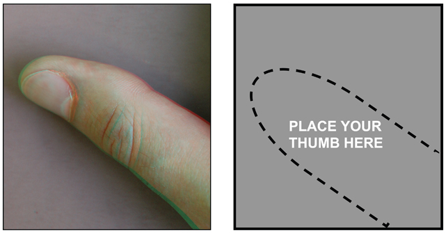
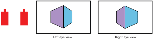
Put on your 3D glasses, set this book 18 inches (46 cm) from your face, and place your thumb in the empty box. Look at the general size and three-dimensional characteristics of your thumb. Now, look at the orthographic 3D photo of the thumb in the box. That orthographic photo was taken with all of the characteristics needed to duplicate a real-life view of a real thumb. The orthographic photo of the thumb will appear as three-dimensional and lifelike as your real thumb (color, style, age, gender, manicure, and hairiness of thumb may vary!). If photographed and viewed under precise conditions, an orthographic photo can duplicate the human viewing situation.
Orthographic 3D photography has an extremely specific set of technical parameters. In order to take an orthographic photo, the stereoscopic 3D camera must duplicate four important aspects of the real-life view. These include:
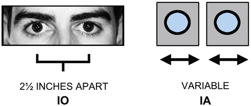
1. IO and IA. The human eyes’ interoccular and the 3D camera lenses’ interaxial distances must match.
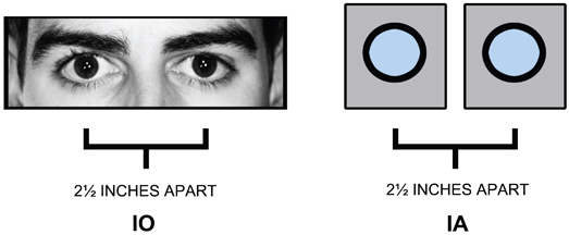
The IO (interoccular) distance between human eyes is 2.5 inches so the camera lenses must be set at a 2.5 inch IA (interaxial) distance.
2. FIELD OF VIEW. The human eyes’ field-of-view and the 3D camera system’s field-of-view must match.
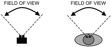
The exact camera image sensor and lens focal length needed to match the human field-of-view will vary depending on the camera system.
3. CAMERA DISTANCE. The distance between the viewer and the real object must be duplicated by the 3D camera and the real object being photographed.
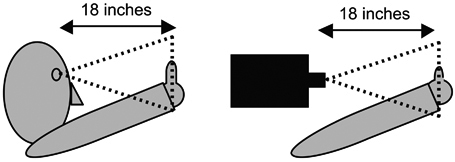
The viewer is 18 inches away from the real thumb so the 3D camera must be placed 18 inches away from the real thumb.
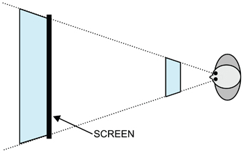
4. VIEWING DISTANCE. The viewer must be the same distance from the real object and the displayed orthographic image.
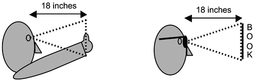
The viewer was 18 inches away from the real thumb so the viewer must be 18 inches away from the orthographic photograph of the thumb printed in the book.
If the orthographic photo and the viewing situation are correct, you will have the identical visual experience as if you were actually 18 inches away from the real thumb. The thumb looks its normal size, normal shape, and has the same three-dimensional quality that it has in real life when viewed from the same distance. A 3D orthographic photograph comes as close as possible to duplicating a real-life viewing situation.
Using the same technique, an orthographic movie can duplicate the three-dimensional experience of watching a live stage show.
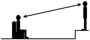
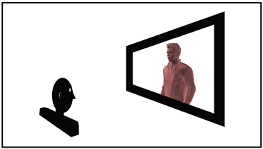
This orthographic movie will replicate the visual experience of one audience member sitting in the first row center watching a live performance.
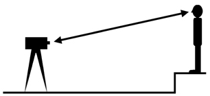
A 3D camera is placed in the first row center, exactly replacing the audience member. The 3D camera is equipped with lenses and image sensors that duplicate the human field-of-view. The entire performance is photographed. There is no camera movement, no lens change, and no editing.

Then, that 3D movie is projected onto a screen so that the on-screen performers are exactly the same size as they were in real life. A single audience member sitting in the same first row center seat can watch the projected image and every spatial aspect of the real theatre performance will be duplicated by the 3D orthographic movie. The orthographic experience is typical for giant screen presentations and high profile thrill-rides in theme parks.
If all 3D pictures and movies were orthographic, there would be no need to discuss any additional aspects of 3D photography. The “3D police” would universally enforce the strict ortho-graphic rules and 3D photography and display would be predictable and simple.
However, the vast majority of 3D movies and television shows are non-orthographic because filmmakers don’t duplicate the shooting and viewing conditions necessary to create the ortho-graphic condition. Filmmakers like to use different lenses, vary the image size, change the 3D settings, edit the shots together, and watch the results on any size screen. Orthographic movies are unique, fun, and extremely immersive for an audience, but non-orthographic 3D movies allow filmmakers to explore additional visual opportunities and variations.
To take advantage of these creative opportunities and visual variations, filmmakers need to understand the technical and aesthetic components of stereoscopic 3D. These components are called the 3D visual variables.
The 3D Visual Variables
Stereoscopic 3D photography offers some important new variables that are used to control 3D pictures.
- Camera Convergence
- Interaxial Distance
- Stereoscopic Window
Visual Variable 1 – Camera Convergence
In traditional 2D photography, one camera with one lens is used to photograph a subject.
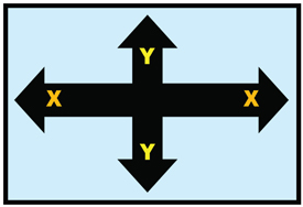
2D pictures are composed in two dimensions on the X-axis (horizontal) or the Y-axis (vertical).
In 2D pictures, the subject can be composed anywhere within the frame’s two-dimensions of width and height: high, middle, and low, on the left, the center, or the right. Even when the subject appears in the distance, it’s still on the flat two-dimensional surface of the screen.
In 3D photography, two cameras, each with its own lens, are used to photograph a subject.
Stereoscopic 3D photography adds the Z-axis to the compositional choices. Now, a subject can be composed on the X-axis, the Y-axis, and the Z-axis.
Put on your 3D glasses and look at these pictures. In 3D, the subject can be placed almost anywhere along the Z-axis, in the foreground, midground, or background. The subject’s position along the Z-axis is controlled by the 3D camera lenses’ convergence.
In 3D, the camera lenses’ convergence point or plane is always the same as the screen plane.
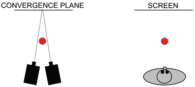
The camera lenses converge behind the subject. When viewed, that subject will appear in front of the screen plane.
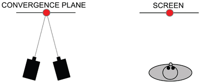
The convergence plane is placed on the subject so the subject will appear at the screen plane.
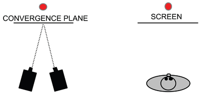
The lenses converge in front of the subject. When viewed, that subject will appear behind the screen plane.
Convergence can be used to place an entire scene anywhere in depth on the Z-axis.
Converging behind the scene places the scene in front of the screen plane.
Converging in the middle of the scene places it half way in front of the screen plane.
Converging in front of the scene will place it entirely behind the screen plane.
The convergence plane does not dictate where the audience will look. Where the audience looks is controlled through composition, lens choice, lighting, staging, and action in the same way filmmakers control where the audience looks in a 2D movie.
Visual Variable 2 – Interaxial Distance
Many 3D camera lenses can mimic the IO of human vision with an IA of 2.5 inches. But most 3D camera systems have an adjustable IA that can be varied depending on the needs of the shot. Most 3D photography does not use a 2.5-inch IA.
The IA distance controls:
- VOLUME – The three-dimensionality of objects in the shot.
- SCALE – The apparent size of objects in the shot.
- DEPTH – The total depth in the shot.
A. IA Controls Volume
Volume refers to the three-dimensionality of objects in a 3D scene. Changing the IA will affect the volume of objects. A small IA reduces volume and a large IA increases volume.
2D Shot
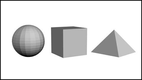
This conventional 2D photo of a ball, a cube, and a pyramid has no volume. The objects are round, square, and triangular but flat, like cardboard cutouts.
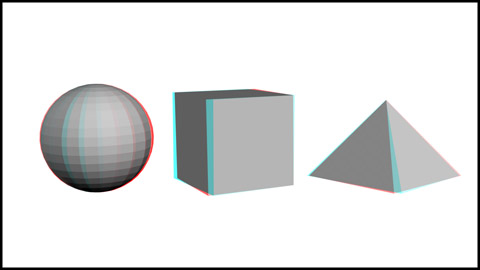
3D Shot
Put on your 3D glasses and look at this 3D photo of the same objects. The ball is not just round, it’s also spherical because it has volume. The cube and pyramid now have volume along their sides.
Many factors can influence the volume of objects in a 3D movie. The lens focal length, the distance between the camera and subject, the screen size, and the audience’s distance from the screen can all contribute to the perceived volume. But the most important way to control volume is by adjusting the IA.
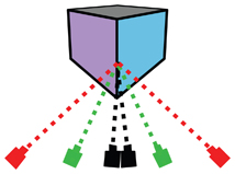
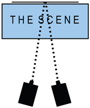
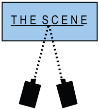
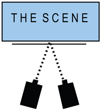
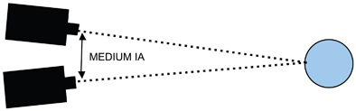
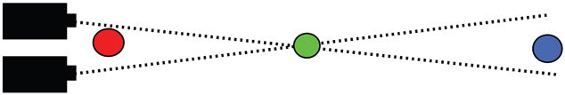
IA creates volume. In this diagram, there are three pairs of cameras looking at a cube. Each pair of cameras (a black, green, and red pair) illustrates a different IA setting. These diagrams are exaggerated to illustrate how IA and volume are linked together.
The two black cameras have a very small IA so they see nearly identical views of the cube. The cube has no volume.
The two green cameras have a medium IA so each camera’s view is different and the cube will have volume.
The two red cameras have a large IA and their views of the cube are extremely different. This gives the cube even more volume.
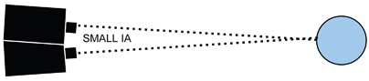
With a small IA, the two camera lenses are closer together and their views of an object are more similar.
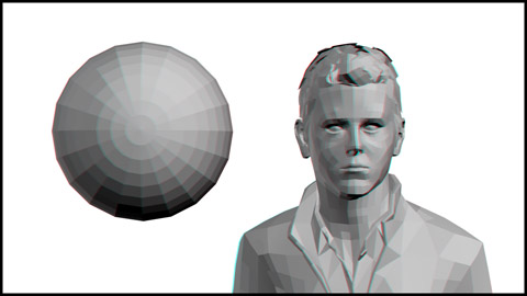
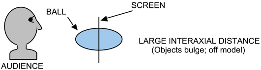
Put on your 3D glasses. With a tiny IA the ball and head have very little three-dimensional volume. They look flat. This is usually called a shape or volume ratio of less than 1. In animation this is often called less than 100 percent or off-model. If there appears to be no volume at all, the volume factor is “zero.”
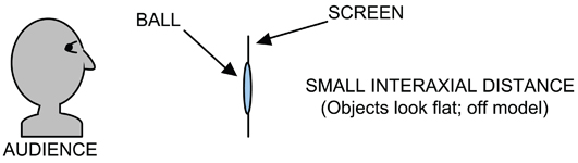
To the audience, an object photographed with a less than ideal IA looks like a flat cardboard cutout.
The IA has been increased and the camera lenses are now farther apart.

Due to the increased IA, the ball and head now appear more round and three-dimensional. The correct shape or volume ratio is 1:1. In animation it’s called 100 percent or on-model volume.
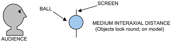
The audience sees the ball with “normal” three-dimensionality or volume.
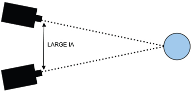
Increasing the IA further adds more volume to the objects in the shot.
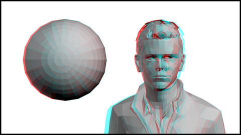
The ball and head now have an exaggerated volume. They appear distorted or stretched in depth. This is called a shape or volume ratio greater than 1. In animation it’s called more than 100 percent or off-model volume.
An overly large IA can increase the volume of objects too much and they appear elongated. The amount of IA needed to create good-looking volume also depends on the focal length of the lens.
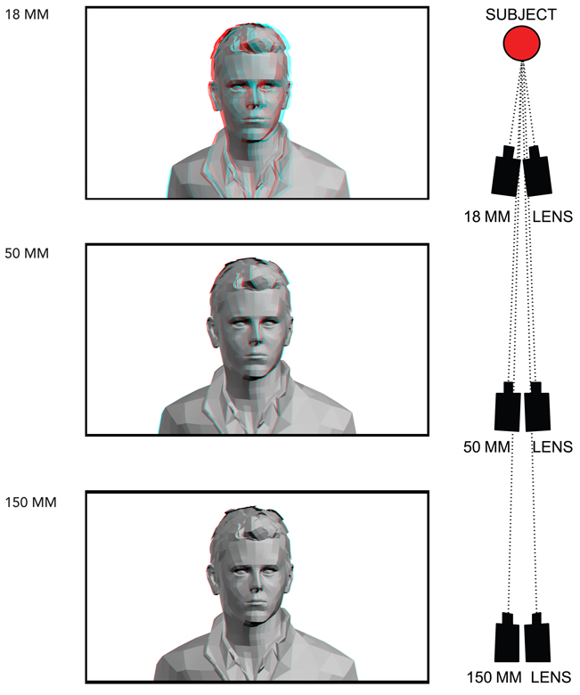
Put on your 3D glasses. All three pictures were taken with the same IA, but different focal length lenses. As the lens gets longer, the volume diminishes. The 18 mm wide-angle lens picture has good volume but the 50 mm lens has less volume and the 150 mm telephoto lens has no volume at all.
The same visual experience occurs with binoculars. Binoculars are a pair of telephoto lenses with an IA of approximately 2.5 inches. When viewed through binoculars, distant objects don’t have any volume because the IA is too small. Binoculars must fit a human’s IO so their IA is too small to compensate for the telephoto lenses.
To retain volume, the IA must be adjusted to the focal length of the lens.
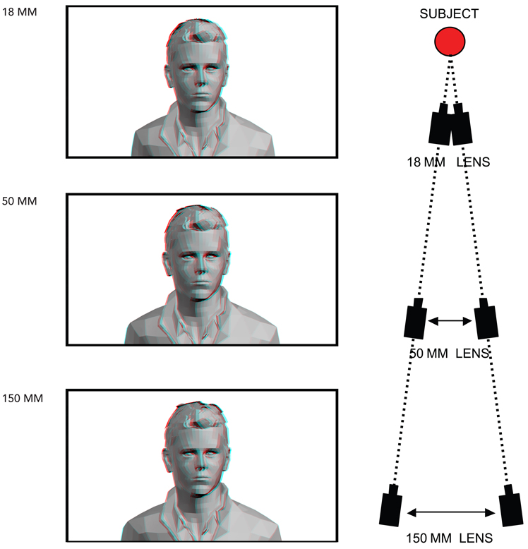
Wide-angle lenses require less IA and telephoto lenses require more IA to create volume.
In these three photos, the IA is increased as the lens focal length gets longer. Adjusting the IA will maintain good-looking volume with any focal length lens. But increasing the IA for telephoto lenses can cause problems with backgrounds.
B. IA Controls Scale
The second visual aspect that is controlled by IA is the size or scale of the entire 3D scene. A small IA may make a scene appear gigantic and a large IA may make a scene appear miniaturized.
Humans are accustomed to seeing the world with a constant IO of 2.5 inches. We can’t change our anatomical IO but 3D cameras can change their mechanical IA. As the IA changes, the scale of the scene may also change. Think about smaller and larger animals that can see in 3D. A mouse has an IO of only a 0.5 inch and a grizzly bear has an IO of 12 inches. If humans are shown pictures taken with an IA smaller than 2.5 inches, like that of a mouse, the scale of the picture may feel too big. This is often called gigantism because the picture appears as if viewed by a tiny creature, not a human being.
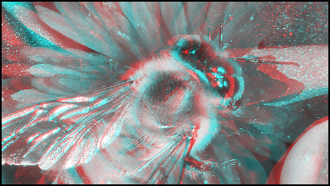
Photo by David W. Kuntz
Put on your 3D glasses. This honeybee, photographed with a tiny IA, may appear gigantic. Regardless of the IA, it is already much larger than in real life so it automatically appears oversized. A big screen makes the bee even larger, but a small IA may add to the feeling that it’s gigantic. In general, gigantism is a subtle effect because audiences are culturally accustomed to oversized images on big screens in 2D and 3D. Close-ups of actors don’t make them look like giants.
The opposite scale illusion occurs if the IA is too large. If humans are shown pictures taken with an IA larger than 2.5 inches, the scene may look miniaturized as if it’s being viewed by something much larger than a human. As the IA distance increases, the scale of the picture may appear more miniature.
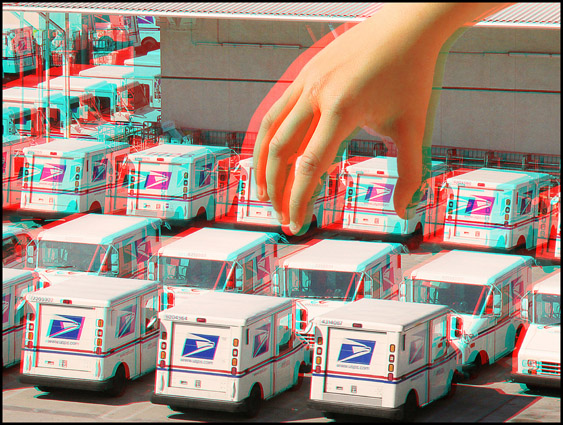
Photo by David W. Kuntz
Look at this photo with your 3D glasses. These full size trucks appear miniaturized because they’re photographed with an overly large IA.
But gigantism and miniaturization don’t always occur. In fact, 3D photography often uses an IA less than 2½ inches. A 3D scene might appear suspiciously giant or tiny because of the IA, but our brain’s knowledge of the actual size of objects tends to ignore the 3D scale problems. The actual subject, the distance between the subject and camera, the lens focal length, and the size of the screen are all factors that determine how a large or small IA affects a scene’s scale.
This book’s small photos cannot duplicate the IA scale issues that may occur with large screens. These photos can only illustrate the general effect.
A scene’s size or scale can also be affected when convergence is combined with the IA.
If a 3D scene (in blue) is positioned, using convergence, close to the audience, the scene may appear miniaturized. The same scene placed at a great distance from the audience, behind the screen, may appear oversized or gigantic.
C. IA Controls Depth
Adjusting the IA changes the total depth of a 3D scene. As the IA increases, the total depth of the scene also increases. As the IA decreases, the total depth of the scene decreases.
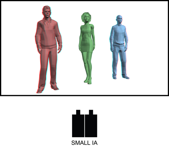
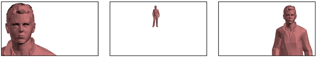
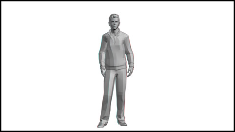
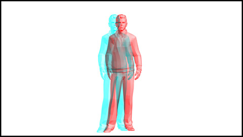
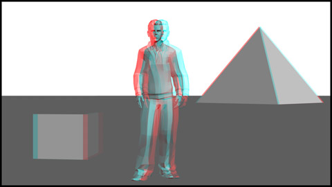
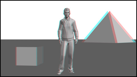
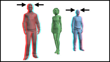
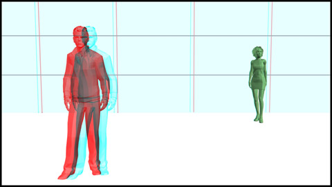
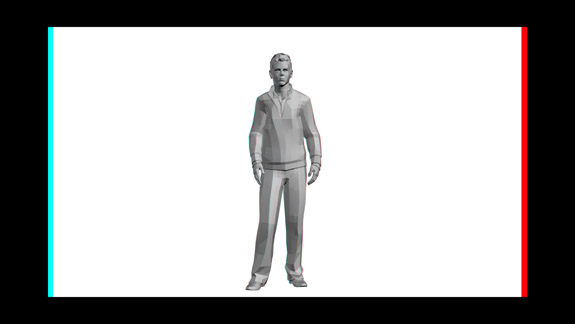
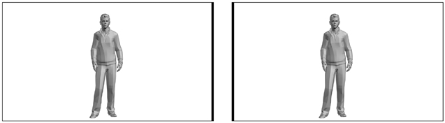
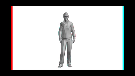
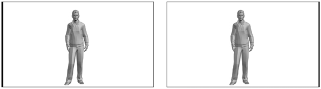
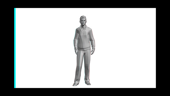
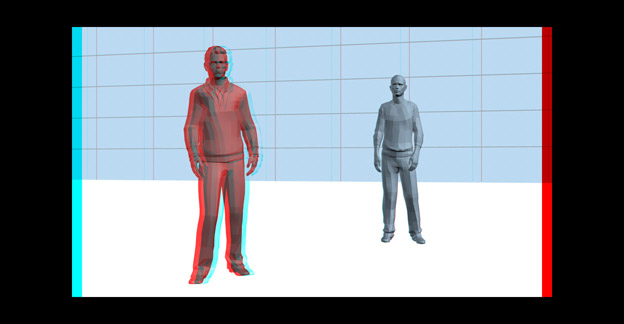
Put on your 3D glasses and look at this shot of the three actors. This picture was taken with a very small IA so there is very little 3D depth along the Z-axis. In fact, the picture looks about the same with or without your 3D glasses.
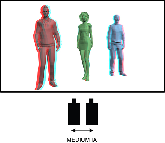
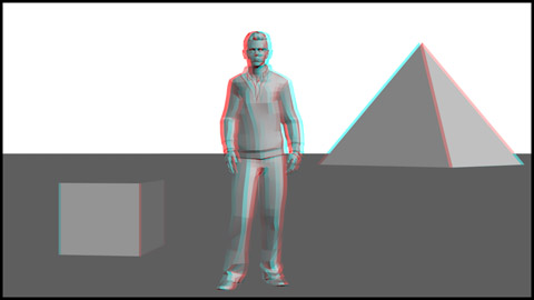
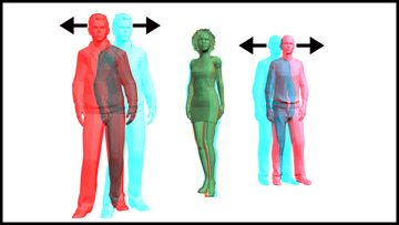
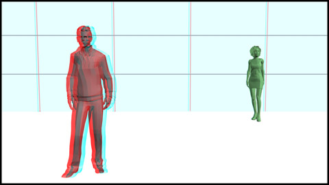
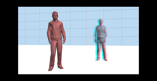
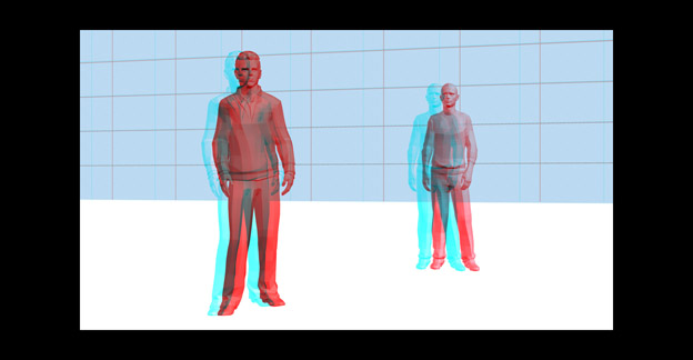
Now the IA has been increased and the shot has more 3D depth. The red actor appears more in the foreground and the blue actor appears more in background.
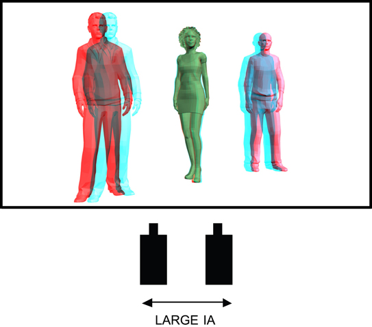
Now the shot has even more 3D depth because the IA was increased again. The red actor is even more in the foreground and the blue actor is farther away in the background.
Parallax
Parallax is the difference between two camera views.
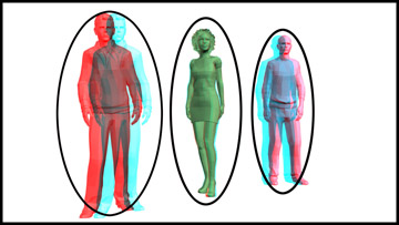
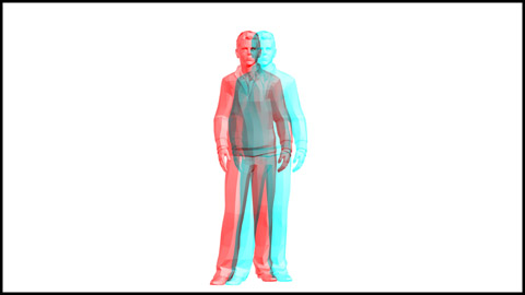
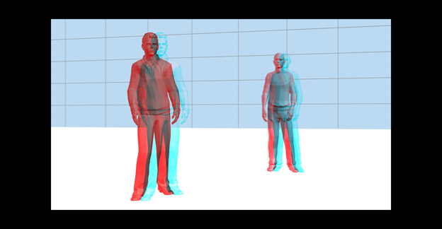
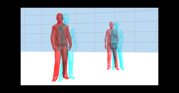
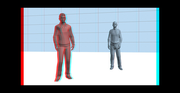
Look at this photo with and without your 3D glasses. Stereoscopic cameras photographed these actors. Because there were two cameras, there are two different views of each actor called an image pair. The difference between the image pair is parallax. The parallax in the red actor’s image pair is easy to see. The blue actor also has an obvious parallax. The green actor has an image pair, too, although it’s difficult to see.
The cameras were converged on the green actor, so the image pair is superimposed over each other. The green actor has zero parallax.
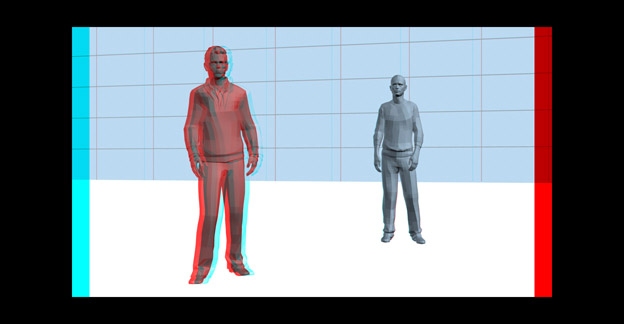
Picture A More parallax
Picture B Less parallax
In Picture A, the red and blue actors’ parallax has been increased. As the parallax increases, the depth increases. In Picture A the red actor is more in the foreground and the blue actor farther in the background. In Picture B the parallax has been reduced and the 3D depth decreases. In both pictures the green actor, with zero parallax, remains in the same place at the screen plane.
Objects in front of the screen have negative parallax and objects behind the screen have positive parallax. For an explanation of why this happens, see Appendix D.
The amount of parallax in an image pair is an important factor in determining where an object will appear along the Z-axis. There are two methods of measuring the amount of parallax in an image pair.
Parallax Measurement Using Screen Percentage
This method is primarily used in live action 3D photography. Special 3D imaging software and display monitors can reveal image pairs as a visual offset.
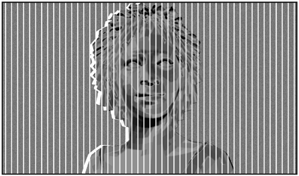
A vertical line pattern divides the image into 50 equal parts. Each line represents 2 percent of the screen’s width. A visual comparison of an image pair to the vertical lines allows the film-maker to estimate the parallax.
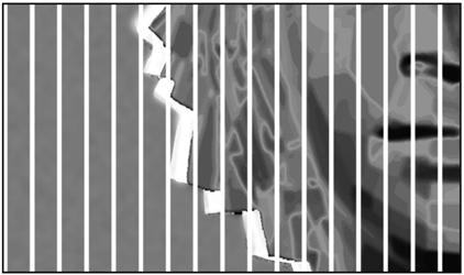
In this enlargement, the image pair offset is almost one line or about 1.5 percent parallax.
Measuring parallax using a vertical line comparison is not precise but it does quickly reveal the approximate parallax for any object in a shot. The advantage to calculating parallax in percentages is that it does not require mathematical conversion as the resolution or screen size changes.
Parallax Measurement in Pixels
The second method for measuring parallax uses screen pixels. Almost all modern 3D motion-picture projection and television transmission is digital. A digital picture is made up of pixels that offer a precise way to measure parallax. This measuring method is used in CG animation, visual effects, postproduction, and 2D to 3D conversion.
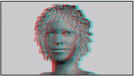
This 3D image pair has a parallax separation of 18 pixels.
This enlargement reveals the 18 pixels of separation.
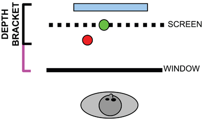
Depth Bracket
The total depth of the scene, from the nearest to the farthest object, is defined by the Depth Bracket. The Depth Bracket is sometimes called the Depth Budget.
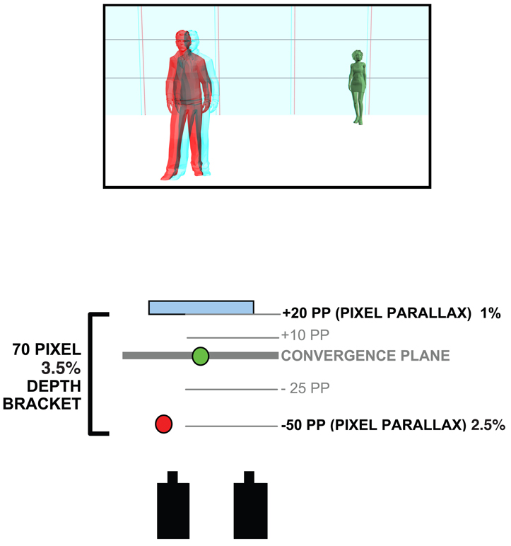
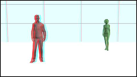
Look at this photo with your 3D glasses. The red actor appears in the foreground, the green actor appears at the screen plane and the blue wall appears in the background.
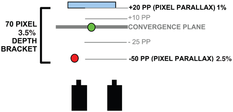
This is a diagram of the photo. The red and green dots are the actors and the blue bar is the background wall. The Depth Bracket indicates the total depth of the scene and can be calibrated in pixels or percentage of screen width. The pixel parallax of the closest object (the red actor) is –50 or about 2.5 percent of the screen width. The pixel parallax of the farthest object (the blue wall) is +20 or about 1 percent of the screen width.
The total depth is calculated by adding together the parallax of the most foreground object and the most distant background object. So, the Depth Bracket is 70 pixels (50 + 20) or about 3.5 percent of the screen’s width.
The Depth Bracket’s size can be adjusted by changing the IA (interaxial distance). As the IA is reduced, the Depth Bracket will shrink and the 3D depth will diminish.
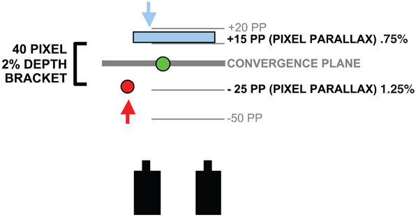
The actors remain in the same physical positions but the reduced IA has decreased the amount of depth. The red actor is now at –25 pixels or about 1.25 percent and the blue wall is +15 pixels or about 0.75 percent.
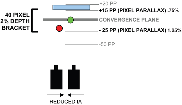
With a reduced IA, the Depth Bracket is now 40 pixels or 2 percent of the screen width.
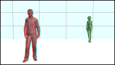
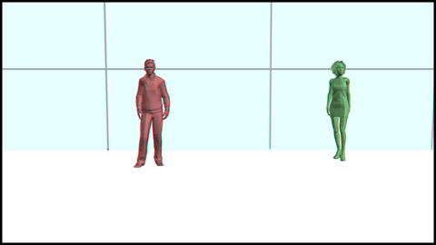
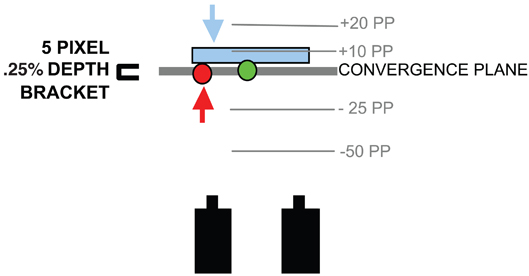
The actors have not moved but a further reduction of the IA has almost eliminated all of the depth.
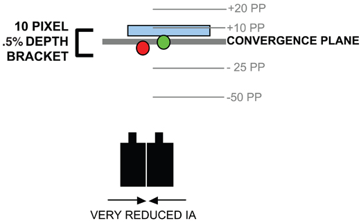
The Depth Bracket is only 10 pixels or 0.5 percent (5 pixels or 0.25 percent for the red actor and 5 pixels or 0.25 percent for the blue wall).
As the IA decreases, the volume is also reduced. Depth Bracket and volume are both affected by IA changes and cannot be separated or controlled independently during photography.
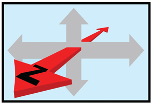
Changing the IA is not the only way to control the Depth Bracket’s size. Restaging the objects and leaving the IA unchanged also alters the Depth Bracket. This will change the composition but maintain object volume.
The original picture and staging has a 70-pixel Depth Bracket or about 3.5 percent. Instead of reducing the IA, the actors and the wall can be physically moved closer to the convergence plane.
The scene has been restaged. The red actor and the blue wall have been moved closer to the convergence plane.
The camera’s IA has not changed. The red actor and the wall have been moved (as indicated by the arrows) so the total Depth Bracket is now only 40 pixels (–25 for the red actor and +15 for the blue wall) or about 2 percent.
The scene has been restaged again. The red actor and the blue wall have been moved even closer to the convergence plane.
The IA has not changed. The total Depth Bracket is only 5 pixels or 0.25 percent. The shot won’t have much Z-axis depth but the volume is maintained.
In the real world, your visual Depth Bracket extends from objects only inches from your face to distant stars in the night sky. Our real-life Depth Bracket is equivalent to about 2,000 pixels.
In a 3D photograph the Depth Bracket also extends from the closest to the farthest objects, but the allowable size of the Depth Bracket is much smaller than in real life due to viewing comfort issues, which are discussed in Chapter 3. The maximum viewable size of the Depth Bracket in a 3D photograph is subjective, but the largest Depth Bracket that most viewers can tolerate is approximately 120 pixels or about 6.25 percent. See Appendix B for more information on Depth Bracket size limitations.
Visual Variable 3 – Stereoscopic Window
There is a frame that surrounds every screen.
In a movie theatre it’s a frame of black curtains and on a television or computer it’s the plastic case that surrounds the screen. On traditional 2D movie and television screens, the frame and the screen share the same flat surface.
But in 3D, that frame becomes a window through which the audience views the world of the movie. You can create excellent 3D movies using the existing stationary frame or you can create a 3D window that floats in space.
In 3D movies this new window is called the Dynamic Stereoscopic Window. This window is not a black curtain but an optical mask that is part of the projected 3D image. The Stereoscopic 3D Window does not have to share the screen surface like a traditional 2D frame. It can move forwards, backwards, or tilt at a variety of angles in relation to the 3D picture. The stereoscopic window is created and controlled in postproduction.
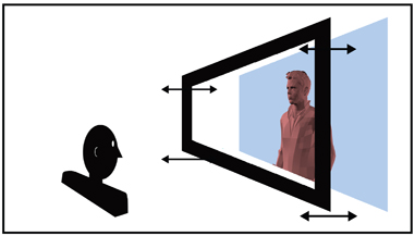
The Stereoscopic Window (not the screen surface) becomes the threshold between two separate visual spaces.
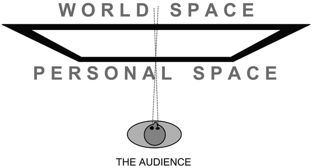
The area in front of the window becomes the Personal Space (or Theatre Space or Audience Space). The area behind the window is called the World Space (or Screen Space).
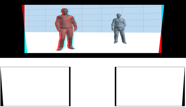
Examine these shots with and without your 3D glasses. Note that the subject’s depth position never changes, but the window moves forward or back.
The Dynamic Stereoscopic Window is created by adding vertical masking to the sides of the picture during postproduction. The left-right position of the vertical masking determines if the window will appear closer or farther from the audience. The width of the vertical masking controls the distance the window moves.

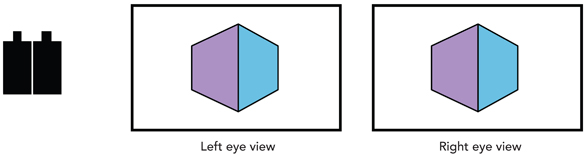
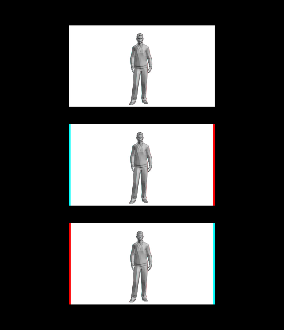
This stereoscopic image pair has been separated to reveal how the window is constructed. In this example, vertical masking is added to the left side of the left eye and the right side of the right eye.
Put on your 3D glasses and look at the combined image pair. The additional vertical masking places the window forward from the screen (or page) surface. As the width of the additional masking increases, the window moves closer to the viewer.
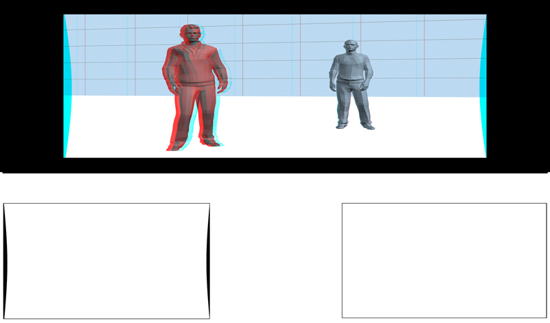
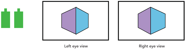
Vertical masking added to the right side of the left eye and the left side of the right eye moves the stereoscopic window farther away. View the results below with your 3D glasses.
The stereoscopic pair’s added masking places the window behind the screen surface. As the width of the additional masking increases, the window will move farther from the audience.
Adding masking on the left side of the left image creates an angled window. The right eye image remains unmasked. The angle of the window can be made more extreme by widening the masking.
Here’s the stereoscopic window angled outward with its left side in front of the screen. The right side of the window remains at the screen surface. This angled window is often used in over-the-shoulder shots to place the window in front of the foreground actor. The window can be angled out on the right side by adding masking to the right edge of the right eye image.
The brightness and color of the window masking must match the viewing environment. Since movie screens are surrounded with black fabric, stereoscopic windows designed for movie theatres are always black. Television and computer screens present a problem because their frame (or bezel) can be a color, metallic gray, or white, which prevents the dynamic stereoscopic window from working. Any vertical edge cropping on theatre or television screens removes the stereoscopic window.
The Depth Bracket and the Stereoscopic Window
Using the Depth Bracket in combination with the Dynamic Stereoscopic Window expands the 3D creative possibilities.
The placement of the Depth Bracket and the Stereoscopic Window determines where along the Z-axis the audience experiences the 3D space. The Depth Bracket and the window can move independently or together.
Positioning the Depth Bracket in Relation to the Window
In these first examples, the Dynamic Stereoscopic Window remains stationary at the screen plane. Only the Depth Bracket position along the Z-axis changes, due to lens convergence adjustments.
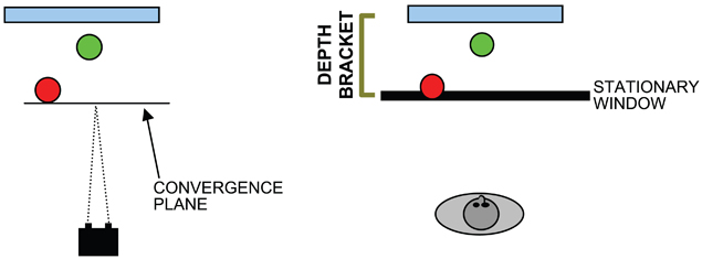
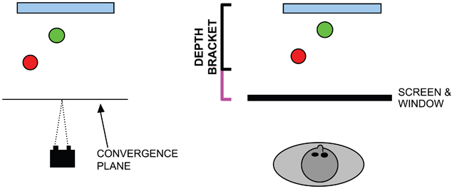
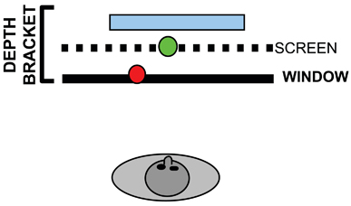
A. The convergence plane is set at the foreground red actor. When viewed, this places the entire Depth Bracket behind the window in the World Space. Picture A on page 51 illustrates this in 3D.
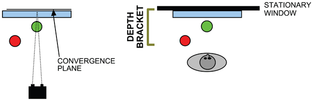
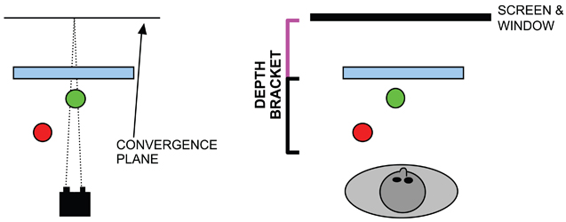
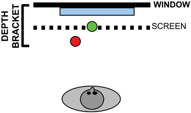
B. The convergence plane is set at the blue wall. The entire Depth Bracket will appear in front of the window in the Personal Space as show in Picture B on page 51. In these two examples, the Depth Bracket position changes due to convergence adjustments. The Stereoscopic Window remains stationary.
A. The entire scene appears behind the window.
B. The entire scene appears in front of the window.
In these two examples, the Stereoscopic Window is set outside the existing Depth Bracket.
C. The convergence plane is set way in front of the red actor. When viewed, the Depth Bracket is far behind the window in the World Space. The Depth Bracket must expand (shown in violet) to include not only the scene but also the window. Picture C on page 53 illustrates this arrangement.
D. A similar situation occurs when the convergence is set far behind the scene. The entire Depth Bracket will appear in front of the window in the Personal Space as illustrated in Picture D on page 53. Again, the Depth Bracket expands (shown in violet) to include the Stereoscopic Window.
C. The actors and wall appear far behind the window in the World Space.
D. The actors and wall appear entirely in front of the window, well into the Personal Space.
Positioning the Stereoscopic Window in Relation to the Depth Bracket
It’s also possible to move the Dynamic Stereoscopic Window and leave the Depth Bracket unchanged. This gives the filmmaker tremendous control in using the effects of the Stereoscopic Window without changing convergence or the position of the Depth Bracket.
E. The entire 3D scene, indicated by the Depth Bracket, exists behind the window. See Picture E on page 55.
F. The Depth Bracket remains fixed. The window has moved to the rear of the Depth Bracket, placing the entire scene in front of the window. See Picture F on page 55.
E. The 3D scene exists behind the window. Only the window has been moved. The convergence and Depth Bracket size and position have not changed.
F. The window has been moved to the back of the Depth Bracket, which places the entire 3D scene in front of the window in the Personal Space.
Moving the window beyond the limits of the scene’s original Depth Bracket automatically expands the Depth Bracket to include the window.
The new Depth Bracket must expand (shown in violet) to include the 3D scene and the Stereoscopic Window.
A Stereoscopic Window far in front of the 3D scene’s Depth Bracket will visually expand the area in the World Space behind the window. The scene feels “deeper” because of the distance between the window and the Depth Bracket.
The side masking can be oriented in a variety of angles and proportions to reposition the entire window or parts of it. Here are two unusual Stereoscopic Windows and how they were created.