CHAPTER 13
Lighting Strategies
NOW LET’S LOOK AT SOME practical application of the theories discussed thus far. This chapter will discuss lighting methods that will make your visualizations come to life and the strategies introduced here are designed to give you the tools to use mental ray efficiently in production. To simplify our discussions, we’ll concentrate on two lighting categories; exterior and interior solutions. Due to the scope of this book, I will intentionally skip studio lighting as this is not a practical application for lighting in architectural visualization. Studio lighting is geared more for things like electronics, cars, and other retail product displays. The strategies discussed here come with specific goals in mind, but as we discovered from the last chapter, global illumination techniques are not entirely discreet from one another, and in fact can be used in conjunction with each other to allow for greater control over scene lighting. Take your time working through the following exercises and continue to revisit them until you fully understand why every step was taken. Be patient and try to extend what you learn here to your own scenes, and when needed, review the theory from the previous two chapters to help remediate any problems that may arise with your scenes.
Using High Dynamic Range Images (HDRI)
We’ll start by a simple comparison between low dynamic range (LDR) and high dynamic range (HDR) images. LDR images come in a variety of flavors such as .jpg, .tif, .gif, etc. These image formats all have red, green, and blue channels to define their color information. Some have more channels to include extra information such as an alpha channel. The truth of the matter is that LDR images can only store a finite amount of information for each channel. Typically, most LDR images are 8-bit. This means that we can only store 256 values, or shades of gray, for each channel. So pure red would be Red=255, Green=0, and Blue=0. Notice that I said there were 256 values yet pure red only uses 255 for a maximum value. This is because the range starts at 0 so the maximum is 255 not 256. Without going into a lesson in color theory, pure yellow would be Red=0, Green=255, and Blue=255.
As we can see, there is a finite range of values we can use per channel in LDR. HDR images are the opposite and allow us to use real values to store color information. This means that we can have a wider range, or high dynamic range of values to define an image, and thus, we can have color intensities that are unobtainable in LDR images. For example, the brightest part of a mid-day sun would be displayed as a pure white pixel in an LDR image that corresponds to a color value of R=255, G=255, and B=255. In an HDR image, this can be defined by real numbers such as R=20,483.058, G=23,945.4286, and B=22,563.4. Although we may not see a difference between these images on a monitor, the difference is there. Because of this, we can use High Dynamic Range Images to illuminate a scene with the real-world lighting.
Typically, HDRIs are created so that the illumination they provide matches the illumination shown in the visible image itself. Typically this is called “in situ”, which means placing your subject in a situation much like placing a CG building in a photo of an existing street corner. Many users believe that all you need is to apply an HDRI within your scene (as we will do shortly) and render the result. This is only half of the story because HDR images only generate the ambient lighting and 3D lighting still needs to be applied to finish the image. Some production houses have proprietary software that scans the HDRI and places lights according to the image’s brightest spots and even sets the light intensity and color based on the HDR image. We won’t be as elaborate as this, and instead will just use our eyes to match the light’s color, location, and intensity.
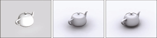
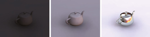
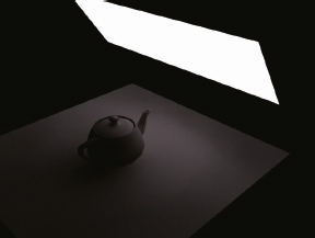
1. Open Ch13-01.max. This is a simple scene consisting of a teapot and plane. Final gather is enabled with a Draft preset.
2. Render the camera view. The result should look like the left image in the following illustration. At this point, the scene is only illuminated by default lighting. Let’s begin the exercise by adding skylight to the scene.
3. Place a standard Skylight anywhere in Top view and render the camera view. The result should look like the middle image of the following illustration. Notice that soft shadows are now present, although because of the draft final gather settings, the quality is quite low. The Skylight feature creates an equal amount of illumination from all directions above the horizon.
4. Change the final gather preset to High and render again. The result should look like the right image.
5. Return the final gather preset to draft so that test renders for the remainder of this exercise take minimal time.
6. Open the Environment and Effects dialog box.
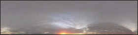
The HDR image we will be using in this exercise is shown in the following illustration. Notice that half of the image is black. This is because skylight should not emanate from anywhere below the horizon, which it would if this half of the image were not pure black. Incidentally, you can download free HDRIs from numerous different vendors such as Dosch Design, Evermotion, and Hyperfocal Design.
7. Click on the Environment Map channel, select Bitmap from the Material/Map Browser, and select the HDR image sunset.hdr. The HDRI Load Settings dialog box appears.
The HDRI Load Settings dialog box is an important feature because it allows us to use an HDRI as is or to use just part of the luminance range. At the top of the HDRI Load Settings dialog box is the image histogram, which is a graphical representation of the luminance range of the image. The farthest left side represents the darkest pixel in the image and the farthest right represents the brightest. When the two red vertical lines are placed at the far extremes of the histogram, as shown in the left image of the following illustration, the entire luminance range is used. When the Black Point and White Point values are adjusted so the two vertical lines are much closer together, such as the right image, a small portion of the luminance range is used. Notice in the right image that everything greater than the white point value is scaled to white and everything less than the black point is scaled to black. This is why so much of the preview image is displayed as pure black and pure white. An easy and suitable way to use this histogram is to either set the white and black point values to the extreme ends of the luminance range, as shown in the left image, or set them to match the Measured Min/Max values, which we will do in this exercise.

8. In the HDRI Load Settings dialog box, set the White Point Linear value to 16.0 and the Black Point Linear value to 0.125.
9. In the Internal Storage section, enable the Real Pixels option (if not enabled), which will allow for the proper storage of the HDR image. Click OK to complete the loading of the HDRI into the environment channel.
If you render right now, nothing will have changed because all you have done is loaded the HDRI as the background image. From the camera’s view, the background is not visible. We need to tell 3ds Max to use the HDRI as the skylight rather than the color swatch found in the skylight we just added.
10. Select the skylight you created and within the Modifier panel set the skylight to Use Scene Environment for its sky color. This will allow the skylight to use the HDRI we placed in the environment channel as the lighting source. In most advanced render engines, using an HDRI within a skylight is the best way to implement image-based lighting.
Once again, if you render right now, nothing will have changed, and you will still see a black rendered image. This is because we haven’t mapped the HDRI properly and we don’t have enough illumination coming from it.
11. Open the Material Editor and drag an instance of the environment bitmap into an empty material slot within the Material Editor. This allows us to adjust additional settings regarding the orientation of the HDRI, as well as intensity values controlled through the Output rollout.
12. Ensure that the HDRI bitmap is set to Environ and change the Mapping to Spherical Environment, as shown in the following illustration. This ensures the spherical HDRI is mapped completely around the scene in a spherical fashion.
13. Render the Camera view. Notice that the image is still too dark right now. We could change the white point in the HDRI so it moves to the left in the histogram, thereby making parts of the HDRI that were previously not giving off much illumination, suddenly give off a tremendous amount. Instead of doing this, which would reduce the dynamic range of the HDRI, we simply need to increase the intensity multiplier of the skylight or increase the Output Amount of the HDRI within the Output rollout of the Material Editor. Changing both of these will have the exact same effect on the rendered image; however, I suggest adjusting the Output value so you can see the effect of the change within the sample slot.
14. Change the Output Amount to 100 and render the camera view. The result should look like the left image in the following illustration.
15. Increase the Output Amount to 300 and render again. The result should look like the middle image in the following illustration. This provides an adequate level of skylight in the scene. Notice how the ground appears to be painted in a blue-purple color. The more you increase the output amount of the HDRI, the whiter the skylight will become until the only thing that prevents it from looking like a mid-day sun image is the lack of strong shadows.
16. Increase the Output Amount to 500 and render again. The result should look like the right image. At this point we need to add direct illumination to the scene.
The HDRI we are using has a definitive light source within it; the sun. So when we add a light to the scene, we need to position it so it matches the location of the sun in the HDRI. Because of an HDRI’s soft shadows, it is often impossible to tell where the sun is in the HDRI based on the HDRI shadows. To locate the sun, we could add a fully reflective sphere to our scene and see where the reflection of the sun in the HDRI is located. Since we already have a teapot, we can just make the teapot fully reflective instead.
17. Apply a fully reflective material to the teapot. If you are using 3ds Max 2012, the easiest way to do this is to apply the Autodesk: Mirror material. If you are using 3ds Max 2009, you should use ProMaterials: Mirror material.
18. Render the Camera view and make note of where the sun is located on the teapot, as shown in the left image of the following illustration.
19. Create a standard direct light anywhere in your scene.
20. Use the Place Highlight tool to move the new light so its specular highlight occurs in the same location as the reflection of the HDRI’s sun. When this is done, the new light will be positioned to match the sun in the HDRI.
21. Enable RayTraced Shadows for the new light and render the camera view. The result should look similar to the middle image of the following illustration. Notice how the areas in direct illumination are completely white and that the shadow of the teapot is actually the same color as the skylight we saw everywhere before the new light was added.
22. Change the direct light Multiplier value to 0.5 to reduce the intensity of the direct illumination.
23. Change the Output Amount for the HDRI to 400 to help reduce the total illumination in the scene.
24. Render the camera view. The result should look like the right image of the following illustration.
25. Adjust the intensity of the direct light and the skylight to achieve an aesthetic balance. If you want to see the final scene as shown in the following illustration, open the file ch13-02.max.
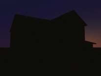
Without the direct light source, your rendering is at the mercy of the overshadowing color derived by the HDRI. HDRIs provide a nice way to illuminate a scene. However, their effect becomes diminished as the strength of direct illumination increases. Therefore, they are really most practical and beneficial in scenes with low amounts of illumination, such as dusk or nighttime scenes. The darker a scene, the more difficult it is to set up lighting with regular lights, and since low illumination is less accurate than strong illumination, you often have to use very high render settings to prevent noise from developing. HDRIs provide a nice solution to this problem.

It is worth mentioning that the previous illustration does not use any tone mapping via exposure control. Exposure control will help minimize hotspots and dark areas in an image, but will also reduce the color contribution of the HDRI.
mr Daylight System (part 1 – Exteriors)
The mr Daylight System is similar to HDRI but offers much more power through an extensive set of tools. The mental ray Daylight System is comprised of a mr Sun and mr Physical Sky shader.
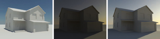
1. Open Ch13-03.max. You’ll notice that it contains a simple white building and a ground plane.
2. Switch to Top view and from the Create panel select the Systems icon.
3. Click the Daylight icon. If you are using 3ds Max 2008 or later, you will be asked if you want to use the mr Photographic Exposure Control.
4. Select Yes, and create a Daylight System centered on the house with default time, location, and North direction. You may get a message saying you are placing a mr Sky and “do you want to place a mr Physical Sky map into the environment channel?”, say yes if you get this message, and skip to step 8.
5. If you didn’t get that message you must select the Modify panel. Notice that both the Sunlight and Skylight sections have fly-out menus that will allow you to choose different types of sunlight and skylight.
6. From the Sunlight drop-down list, select mr Sun and from the Skylight drop-down list, select mr Sky. As soon as you select the mr Sky, you will be asked if you want to place a mr Physical Sky map into the environment channel.
7. Select Yes.
8. Open the Environment and Effects dialog box, and from the mr Photographic Exposure Control rollout, click on the preset drop-down list and select Physically Based Lighting, Outdoor Daylight, Clear Sky. Press Render Preview. Now you can adjust the EV value spinner while watching the preview thumbnail. If you’re familiar with photographic settings, you will probably find it more beneficial to not use a preset and to adjust your exposure control through the three critical components found both in this rollout and the real world. They are shutter speed, film speed, and f-stop. For the sake of simplicity, we will use a preset.
9. On the Render Setup dialog, under Indirect Illumination, make sure Final Gather is set to Draft.
10. Switch to the Camera view and render the scene. The result should look like the left image of the following illustration.
11. Use the Motion panel to change the time of day to 6AM and render the Camera view again. The result should look like the middle image of the following illustration. Although the preset we used for exposure control provided a suitable image in the previous rendering with the sun positioned high in the sky, this last rendering appears much too dark with the sun being as far above the horizon as it is; approximately 15 degrees. Rather than correcting this with the more complicated Photographic Exposure settings, which requires knowledge of the photography settings just mentioned, we can instead provide a quick fix to the exposure problem by reducing the Exposure Value.
12. Change the Exposure Value from the default value of 15 to 14 and render again. Notice that the image is twice as bright. This is because when you reduce the Exposure Value by 1, the shutter speed is reduced in half. This means that the shutter of the camera stays open twice as long allowing twice as much light to exposure the image. You can even see the actual Shutter Speed value changing as you change the Exposure Value. Cameras in the real world use these same shutter speeds and when you want to change shutter speed on a real camera, you either double the speed or reduce the speed to half. At this point, the image is still too dark right now so one more change is in order.
13. Reduce the Exposure Value from 13 and render again. The result should look like the right image of the following illustration. This image appears to be properly exposed and the amount of illumination in the scene appears to be what we could expect to see with the sun just above the horizon early in the morning.
14. Save your scene using a new name for use in the next exercise. If you want to see the final scene as shown in the following illustration, open the file ch13-04.max.
Note how in the previous illustration the skylight color and intensity is driven by the azimuth and altitude of the Daylight Assembly head. This is typically driven by the time of day entered in the Motion panel; however, this can be overridden by simply selecting Manual Override and positioning the assembly head at any location you like.
The daylight system also provides a sun disc that can be visible within the render. The location is driven by the extrapolated location of the sun’s direction vector not the physical location of the daylight assembly head. To understand where the sun disc will appear when rendered, it is best to set the daylight’s Orbital Scale to an exorbitant value.
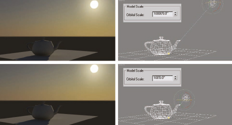
Figure 13-1. The rendered sun disc location matches the assembly head only when a high orbital scale is used.
mr Daylight System Parameters
The Daylight System provides a great way to implement real-world exterior lighting. Although you can use standard or photometric lights with this system, the mental ray Daylight System found in 3ds Max 2009 and later makes the mr Sun, mr Sky, and mr Physical Sky an amazing combination. When used in the way these features were designed, all three are linked together and both the mr Sun and mr Physical Sky include an Inherit from mr Sky option, which should be left enabled unless you have a specific reason for them to be disabled. Incidentally, the mr Physical Sky parameters are only accessible by creating an instance of the environment channel within the Material Editor. Fortunately, most of the parameters for these three features are self-explanatory, so here we’ll focus on some that are not.
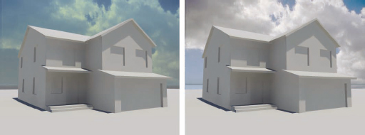
In the Command panel, there is a rollout labeled mr Sky: Haze Driven (mr Sky), and within this rollout is the Haze setting. This setting controls the amount of particulate in the atmosphere, which helps determine the color of the sky and skylight. This value is set to 0, by default, which causes no haze to be generated. Increasing it up to maximum value of 15 simply increases the strength of the haze, while the color of the haze is dictated by the position of the sun. As you can see in Figure 13-2, raising this setting to a maximum value of 15 and changing the position of the sun creates a wide variety of sky and skylight color. In this example, the position of the sun was changed by simply changing the time of day.

Figure 13-2. Haze at full value (from left to right; 6am; 8am; 10am; 12pm; 2pm; 4pm; 6pm).
We can also add a cloud texture to the Haze component to get the look of distant clouds.
15. Continue from the previous exercise or open Ch13-04.max.
16. Select the daylight assembly and within the Modify panel, change the Haze value from 0.0 to 2.0 and render the Camera view. A subtle haze is generated.
17. Drag an instance of the mr Physical Sky shader from the Environment and Effects dialog box to an empty slot in the Compact Material Editor.
18. Within the Material Editor, deselect the Inherit from mr Sky checkbox and render again. The sky returns to showing no haze because you have overridden the haze setting in the Modify panel.
19. Click the Channel button to the right of the Haze parameter and add the bitmap Haze_Clouds.jpg to this channel. Deselecting the Inherit from mr Sky option overrides the haze setting within the Daylight system and loading a bitmap here overrides the Haze setting within the mr Physical Sky shader.
20. Within the Output rollout of the bitmap you just loaded, increase the RGB Level of the cloud texture to 10 to compensate for the effect of exposure control. Without doing this, the map would be too faint. As you increase the RGB Level, you also cause the Haze color to be influenced. An alternate to this technique is the Use Custom Background Map.
21. Enable the Use Custom Background Map within the mr Physical Sky shader and copy (not instance) the Haze_Clouds.jpg into this map channel.
22. Change the Output Amount to a value of 1000. Also increase the RGB Level to 10. This will compensate for the exposure control and display the cloud image properly in the background. Also make sure the Coordinates rollout shows the Environ button selected, and Mapping set to Screen. The following images show the result of both methods. The left is accomplished by placing a cloud map in the Haze channel, while the right is accomplished by replacing the background image entirely.
The next feature we’ll look at is Night Color. The Night Color represents the darkest color your sky will change to when your sun goes below the horizon. It’s important to note, however, that the color you specify will be the darkest only when exposure control is not allowed to affect the background.
1. Open the file Ch13-04.max again to return to the scene we used at the beginning of the last exercise.
2. Render the Camera view to remind yourself what the scene looks like right now.
3. Drag an instance of the mr Physical Sky shader from the Environment and Effects dialog box to an empty slot in the Material Editor.
4. Within the Material Editor, deselect the Inherit from mr Sky checkbox.
5. Select the daylight assembly and within the Motion panel, change the time of day to 4AM so the sun is just below the horizon.
6. Render the Camera view. The result should be a very dark scene.
7. Click on the Night Color swatch within the Material Editor and change the Blue component to 0.2. Click OK to close the dialog box. This changes the Night Color to a very dark blue.
8. Render the Camera view. Notice that nothing has changed. The reason is because exposure control is affecting the final colors within the image. When the sun is below the horizon as it currently is, we need to adjust exposure control because it’s configured for a daytime scene.
9. Remove exposure control entirely and render the Camera view again. Notice that the night color you just set is now the dark color in the sky, as shown in the following illustration.
The next feature we need to discuss is Aerial Perspective, which contains a setting called Visibility Distance. This setting determines the distance at which a 10% haze is generated. This haze is needed in large exterior scenes where the viewer can see to great distance, because without it there is a diminished sense of scale. This value is set to 32,808’4.781” by default, which is exactly 10 kilometers. The following exercise helps illustrate this important setting.
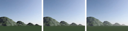
10. Open the file Ch13-05.max. This scene contains a mountain range that spans approximately 10K, which is the same distance the visibility distance is set to by default.
11. Render the Camera view. Notice that the image lacks depth and scale, as shown in the left image of the following illustration. This is because there is no haze, even though one would expect to see it for such a view.
12. Select the daylight assembly and open the mr Sky Advanced Parameters within the Modify panel. Notice that Aerial Perspective is disabled.
13. Enable Aerial Perspective and render the Camera view again. Nothing has changed because the Visibility Distance is set to 100,000 feet, which is beyond the last mountain in the background.
14. Change the Visibility Distance to 30,000’ and render again. The result should look like the middle image of the following illustration.
15. Change the Visibility Distance to 10,000’ and render again. The result should look like the right image of the following illustration.
We can also use this as a Lens or Volume shader within the scene.
16. Disable Aerial Perspective.
17. Open the Camera Effects rollout within the Renderer tab of the Render Setup dialog box.
18. Within the Camera Shaders section of this rollout, click on the None button next to Volume and load the mr Physical Sky map type.
19. Drag an instance of this map into the Material Editor.
20. Change the Visibility Distance to 10000’ and render the Camera view. The image returns to its initial look, as shown in the left image of the following illustration.
21. Change the Visibility Distance to 30,000’ and render again. The result should look like the middle image.
22. Change the Visibility Distance to 1,000’ and render again. The result should look like the right image.
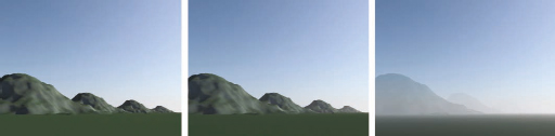
There is a key difference when using the mr Physical Sky map as a Lens or Volume shader. The Lens shader will not be visible in raytraced reflections but the Volume shader will.
Lastly, we’ll look at the Non Physical Tuning parameters, accessible in the mr Sky Advanced Parameters rollout of the Modify panel or within the mr Physical Sky map. These parameters will adjust the overall coloration of the render. For example, we could warm or cool the coloration of the rendering by adjusting the Red/Blue Tint value. Positive values make the rendered image redder and negative values make the rendered image bluer. Figure 13-3 illustrates the differences between these settings.

Figure 13-3. Various Red/Blue Tint values from left to right; -1, -0.5, 0, 0.5, and 1.
mr Daylight System (part 2 – Interiors)
Having discussed exterior lighting in the first half of this chapter, we now switch the focus to a discussion on interior lighting. We will once again use the daylight system for our interiors, but instead of calculating GI entirely through final gather, we will also have to rely on photo mapping. Photons are the best way to allow light to permeate into a scene, unlike final gather, which on its own does not allow enough light through small areas such as door and window openings. Although sky portals can fill this gap, photons may still be required to spread the illumination throughout the scene. Even sky portals can emit photons for this purpose and we’ll look into this later in this chapter. For now, we’ll look at using a photon map to bounce light throughout our scene, and then allow final gather to use this ‘sprayed’ map to obtain a better rendering.
Using photons and final gathering together
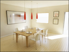
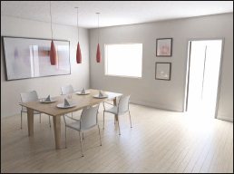
1. Open Ch13-06.max. This is a simple interior scene illuminated entirely by a daylight system. Materials are already applied but global illumination has not been set up yet. The following image shows what we will produce by the end of the exercise.
2. Within the Processing tab of the Render Setup dialog box, enable the Material Override option.
3. Load the Arch & Design material as the override material. Using a material override during initial lighting setup is useful for reducing test render times and for facilitating the setup process. With only one material, the number of things that must be controlled and understood are reduced and there are far fewer variables involved.
4. Create an instance of the material override in the Material Editor.
5. Change the Reflectivity of the new material to 0 and set the Diffuse Color to 75% gray. To set the color to 75% gray, simply enter a value of 0.75 for the RGB components.
It’s important to note that the window glazing has been hidden for the lighting setup because if it were visible, it would receive the override material and stop light from passing through.
6. Switch to Top view and select the daylight system that has already been created for the scene. Notice that when you select the daylight system, pink lines appear. This is the Photon Target feature. Essentially, the pink lines represent the tube photons will be shot through and it effectively concentrates the spray so fewer photons are wasted. The target has been adjusted so it’s just large enough to cover the openings of our room. You can access the controls for the Photon Target within the mr Sun Photons rollout of the Modify panel.
Since we’re using a daylight system, we need to use exposure control.
7. Enable mr Photographic Exposure Control and use the preset called Physically Based Lighting, Indoor Daylight. Right click the Camera Viewport, and then press Render Preview.
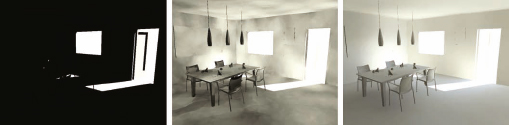
8. Switch to Camera view and render the scene. The result should look like the left image of the following illustration. There is no GI in the scene so the only possible result with the daylight system is pure white for direct illumination and pure black for shadows.
9. Within the Indirect Illumination tab of the Render Setup dialog box, enable GI and render the Camera view again. The result should look like the middle image of the following illustration. Despite the noise, we’re getting good penetration of photons within the scene. The key here is to make sure that most, if not all, of the surfaces receive some illumination from the photon map. Typically you can keep the average number of photons per light set to 10,000. If you were to have more light sources in the scene you would divide the average number of photons by the number of lights. For example, if we had 3 lights in the scene we could get away with an average of 3,333 photons per light since this would total 9,999 photons for the scene. If there are not enough photons to illuminate all of the surfaces in the rendered view, increase the average number of photons per light until there are enough photons to give a good distribution.
10. Enable Optimize for Final Gather. This will allow the final gather process to more efficiently read the irradiance values from the photon map.
11. Enable Final Gather and set the preset to Draft.
12. Within the Advanced section of the Final Gather rollout, disable Noise Filtering (Speckle Reduction) by clicking on the drop down list and selecting None. This will enable every final gather ray to be used, which in draft mode is 50 rays per final gather point. This filter should only be used if you see strange bright artifacts when using final gather. Remember that the process will reject any sampled ray that is abnormally different from the rest.
13. Render the Camera view. The result should look like the right image of the following illustration.
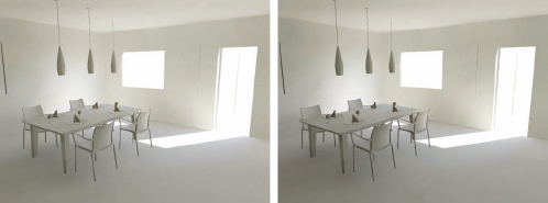
14. Within the Image Control section of the mr Photographic Exposure Control rollout, set the Highlights (Burn) value to 0.05. This will remove most of the overexposed highlights by the door and back wall.
15. Increase the Shadows value from 0.2 to 0.5. This will increase the contrast and depth of the shadows.
16. Render the Camera view again. The result should look like the right image of the following illustration.
You’ll notice that the scene has a smoother GI quality but is still far from what is desired. There are still some artifacts at the feet of the table and the scene lacks detailed shadows. We can easily adjust our final gather settings to get better connecting shadows and detailed lighting, but this is at the expense of longer render times. A better way is to use Ambient Occlusion. Ambient occlusion (AO) is the measure of how much of the surroundings are occluded, or blocked from view, at any given point on a surface. An AO image is always grayscale, and is often referred to as a dirt pass, because it can be used to add a dirty look to what would otherwise be surfaces that are too perfectly clean to be realistic. It can also be used here to add detail and depth to shadows.
17. Within the Special Effects rollout of the material you assigned as an override, enable the Ambient Occlusion option.
18. Render the Camera view. The result should look like the left image of the following illustration.
Ambient Occlusion samples points along the geometry surface to check for any geometry within a specified proximity of that point. If there is, the surface point renders darker depending on the number of sample rays that detect adjacent geometry. We can specify this sampling radius by adjusting the Max Distance value. Increasing this value increases the spread of the shadows.
19. Increase the Max Distance value from the default 4” to 2’ and render the Camera view again. The result should look like the right image of the following illustration. Notice the increase in depth in shadows everywhere; especially the plates on the table.
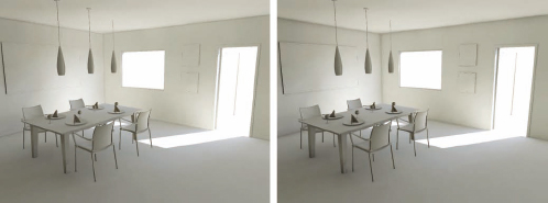
Although ambient occlusion gives us great results, they may not be as accurate as we might like. For example, notice that there is a pronounced shadow in areas like wall corners. This can be fixed by using the Use Color From Other Materials (Exact AO) option. This method will look at adjacent materials and include their properties in the AO calculations. This will take a little longer to render but will give us more accurate results without a huge hit to render times.
20. Enable the Use Color From Other Materials (Exact AO) option and render the Camera view. The following illustration shows the before (left) and after (right) images. Notice how the ceiling is still defined without having an over-exaggerated dark crease. Because AO can be applied on a per material basis, we can tailor the shadowing to our needs by adding as much or as little AO as we want. We’ll look at this later in this chapter.
To improve the image quality further, implement some of the strategies discussed in the previous chapter regarding final gather. You can always resort to some of the presets to make this even easier.
At this point we’re ready to start texturing and applying materials. The main material we’ll be concerned with is the mental ray Arch & Design, which we’ll talk about in more detail in the next chapter. Because we had a universal material assigned with the material override, we didn’t have to worry about how photons interact with the scene. For example, material color will have an impact as to how much light is reflected off of every surface. Dark materials will absorb the photon energy and lighter materials will allow the energy to propagate more. Because of this, we may have to play with the exposure control settings to compensate for the addition or loss of light energy.
4. mr Sky Portals
Sky portals were introduced with 3ds Max 2008 and can be used to enhance the effects of final gather without necessarily requiring any photon mapping. Sky portals can be thought of as a conduit for skylight; they derive their information from a skylight, an environment map, or a custom shader. Although they need to derive their lighting source and color from other sources, they act very much like an area light. This means that a sky portal is able to create realistic area shadows. It is important to note that sky portals can also be used to emit photons. Therefore, everything we’ve done in the previous section is applicable here.
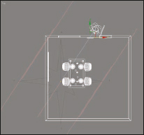
1. Open Ch13-07.max. This is the same scene we’ve been using, except the daylight system has been removed and replaced with a skylight.
2. Switch to a Front view, and create the photometric light called mr Sky Portal just inside the window opening and just inside the door opening. Position and size the sky portals so they fill the openings as much as possible without touching any geometry. Make sure the light direction arrow points to have the sky portals push light into the room.
3. Switch to Top view to place the portals so they are flush with the outside surface of the walls. You could also choose to position the sky portal inside the room so it is not affected by the glass within the windows in any way.
4. Render the Camera. There is virtually no illumination because the portals are using the skylight as the color/light source, as you can see in the Advanced Parameters rollout of each sky portal.
5. Select the Skylight and set its multiplier to 30,000. We have to do this because we’re still using the exposure settings for the daylight system and the skylight is what the sky portals will use as their luminance source now. An intensity multiplier value of approximately 30,000 is needed to create about the same amount of light as that of a daylight system.
6. Enable Final Gather and set it to Draft mode.
7. Render the Camera view. The result should look like the following illustration.
Note that you can simply add the mr Sky Portal like any other light. The only difference is that you need to specify where the illumination is coming from (i.e., skylight, environment channel, or a custom shader). As an additional note, the only shape option currently is the rectangle, so for round windows several smaller sky portals may be needed to fill the shape.
mr Sky Portal Parameters
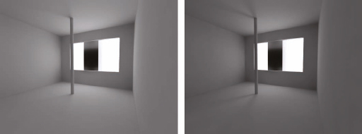
1. Open Ch13-08.max. This scene contains a window opening with a large box just outside of it.
2. Render the Camera view. Notice that the pole in the center of the room casts a single shadow, as shown in the left image of the following illustration.
3. Select the mr Sky Portal and enable the Shadows From “Outdoors” option.
4. Render the Camera view. Notice that the pole now casts a double shadow (right image) as if we had two sky portals in two separate windows. This option allows objects behind a sky portal to influence its area shadows. This means that if we have any geometry that is outside the window, area shadow calculations will be calculated based on the amount of occlusion in the opening. The result is a longer rendering time due to the added complexity of area shadow calculations, but realistic occlusion of exterior geometry, such as trees, shutters, or anything else. As an additional note, when this object is enabled and objects are blocking the opening, as in this scene, the result is also a reduced amount of light entering the opening.
Some additional important options include the following:
• Visible to render – This option allows you to use the mr Sky Portals as bounce cards to add specular highlights. This option should only be used when sky portals are outside of the view, as they will occlude anything behind them and act as self-illuminated planes.
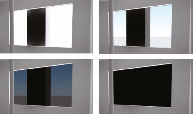
• Transparency – This option is a little confusing for many users. It adjusts the exposure value for objects that are seen through the mr Sky Portal. Typically when balancing exposure, interior scenes are substantially different in light levels compared to the outdoors. This is evident in any interior photograph looking through an exterior window. Either the interior is lit well with the exterior blown out, or the exterior is seen through the window and the interior is very dark. This discrepancy is what transparency compensates for. A transparency value of black will occlude all objects and the environment behind the portal. All other values allow for light balancing. The following illustration demonstrates this with various levels of transparency applied to the sky portal.
5. Self illuminated materials
Self illuminated materials allow you to further exploit the power of final gather. There are many ways to use self illumination; however, the Arch & Design material has quantitative values we can assign for luminance values.
1. Open Ch13-09.max. This scene contains a simple teapot on a plane with another plane that will act as an area light. There is also a hidden and disabled omni light, which is used to disable default lighting.
2. Enable Final Gather with Draft mode.
3. Open the Material Editor and notice that there are two materials applied in the scene. One is a basic Arch & Design material assigned to the ground plane and the teapot, while the other is what we’re going to use to create our self-illuminated material.
4. Select the Illumination Material in the Material Editor. Change the material from a Standard material to an Arch & Design material.
5. Disable reflections by setting Reflectivity to 0.
6. Enable the Self Illumination option in the rollout of the same name. If you want to establish the self-illumination intensity with physical units that respect the size and scale of your scene, this is certainly an option. However, for this example we’ll only concentrate on the Unitless option, which acts like a multiplier. By default, the luminance is set to 1.0, but we can increase or decrease this as necessary to achieve the appropriate amount of illumination.
7. Enable the Illuminates the Scene (when using FG) option. This is an important option because without it the material will appear to be self illuminated, but it won’t illuminate the scene.
8. Render the Camera view. The result should look like the following illustration.
We may need to adjust the final gather settings depending on the size of the self-illuminated geometry. Larger areas can get away with less detailed settings but small areas need a much more detailed final gather map to create acceptable results. If we want to create neon, for example, the size of the illuminated surface is quite small. To allow as many final gather rays to see it, we would need to increase the number of Rays per FG Point, and increase the Initial FG Point Density and disable Noise Filtering (Speckle Reduction). This way, there is a greater chance that the final gather rays along the surface will see the illuminated tube. In the following illustration, notice how much more illumination detail there is with the image on the right, which uses better final gather settings.
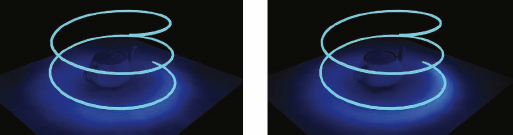
Figure 13-4. Difference between low final gather settings and high settings for small self illuminated material geometry.
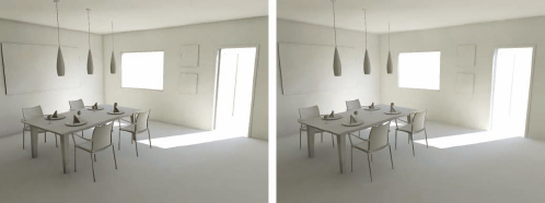
There are many applications for this technique and I’ll leave you to explore the possibilities. For now we’ll look back one more time to the simple dining room scene, only this time we’ll illuminate the room using self illuminated planes outside the window and door. Because this scene doesn’t use photon mapping we’re relying entirely on final gather to generate our illumination. Because of this, we need the final gather process to see further into the scene. This can be accomplished by setting the Diffuse Bounces setting to a value of 2 or 3. Higher values will lead to exaggerated color bleeding. If you want to examine this scene with this configuration, open the file ch13-10.max.
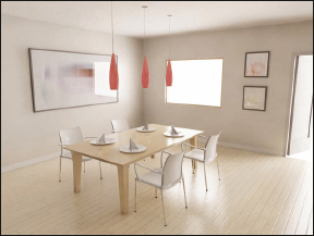
Figure 13-5. Dining room scene lit entirely by a self-illuminated plane outside the window.
Summary
As you can see, there are many methods by which to illuminate your scenes. Knowing what’s available and how to implement it is crucial to being able to meet expectations. At the end of the day, you need to be able to balance rendering speed vs. quality. There is so much more that is available to you within mental ray and this only scratches the surface. Take the information presented in this chapter and research points you may have questions about. The main ideas presented here deal with using photon mapping and final gather when appropriate. Typically, any exterior scene can forego the use of photon mapping since final gather gives more than enough lighting information. Interior scenes, or scenes that use artificial lighting, are better suited to using photon maps. We can then use final gather as a means of smoothing out and refining the GI solution by using the photons’ irradiance values in the final gather calculations. This has been further refined by the use of portal lights that allow us the possibility, depending on the scene of course, of solely using final gather as a method of calculating the bounced light. To this, we can also add self-illuminated materials to the mix to come up with complex architectural lighting.