
CHAPTER 15
Unwrap UVW
GOOD TEXTURE APPLICATION IS AT the heart of any great 3D scene, and far too often, 3D artists do not spend enough time in this area of the design process. As with any project, time becomes an issue and everyone looks for fast and effective ways to get the job done. In the area of texture application, the Unwrap UVW modifier is certainly a tool with enough power and versatility to produce amazing results in minimal time. In this chapter, we’ll learn how we can exploit the power of this modifier for architectural visualizations and ultimately increase productivity and efficiency.
Standard UVW maps come in a variety of flavors and are typically planar, cylindrical, spherical, box, or face in nature. While easy to apply, they fall short when faced with complex or organic geometry. The Unwrap UVW modifier provides a unique way of placing a texture; based on the geometry of an object rather than through a predefined gizmo. To better understand how this modifier works, we’ll start by looking at a simple cube and then move on to more complex methods.
Texturing a Die
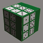
1. Open the file ch15-01.max. This scene contains a simple box with the texture of a die applied to each side, as shown in the next illustration. We’ll use the Unwrap UVW map to apply unique portions of the texture to each face of the box.
2. Apply the Unwrap UVW modifier to the box.
3. Within the Parameters rollout, click the Open UV Editor button. This opens the Edit UVWs dialog box. This window will allow you to select pieces of the geometry and position them over unique portions of our texture map.
4. In the Selection Modes section of the dialog box, select the Face Sub-object Mode icon (third from left). This allows us to select faces directly on the object within the viewport or within this dialog box. You can also switch sub-object modes by opening the modifier in the modifier stack.
![]()
5. Move the Edit UVW dialog box off to the side so you can see an unobstructed view of the geometry.
6. In the Modify panel, disable the Ignore Backfacing option.
7. Select all faces of the geometry within the viewport. When using Unwrap UVW you can select sub-objects level either within the viewport or within the Edit UVW dialog box. We’ll do so with the dialog box shortly.
8. From the Mapping menu of the Unwrap UVW dialog box, select Flatten Mapping. The Flatten Mapping dialog box opens.
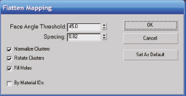
For square geometry such as cabinets, desks, or any other type of rectilinear furniture, we wouldn’t need to adjust any of the parameters in the Flatten Mapping dialog box and could just click OK. If the geometry was more organic, we would need to experiment with the Face Angle Threshold to obtain better results. This looks at the angular difference between normals of adjacent faces. If the difference exceeds 45 degrees a new mapping group is created. I would recommend coming back to this setting once you’ve finished the chapter and experiment with different values on a simple teapot to get a better understanding of this parameter.
9. Click OK to complete the command. Notice that 3ds Max has separated each side of the box in the Edit UVW dialog box for easy manipulation, yet you can clearly see in Perspective view that your geometry is intact.
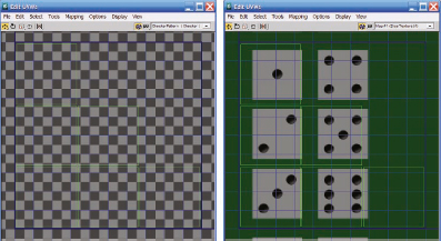
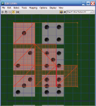
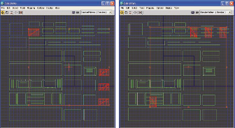
10. Click inside any viewport to deselect the faces that are currently selected. The Edit UVW dialog box should look like the left image in the next illustration.
11. At the top-right of the Edit UVW dialog box, click the Show Map icon to disable this feature. This feature is enabled by default but it was disabled here to show you how you can make it easier to see the 6 green rectangles (representing the 6 polygons of the box) and the blue grid system that serves as a guide for using the Unwrap UVW feature. What we need to do now is load the texture into the Edit UVW dialog box and position each of the green rectangles over its respective portion of the texture.
12. Click on the Show Map icon again to enable it again.
13. Click on the drop-down menu to the right of the Show Map icon and select Map#1. The image of the die is shown as the background of the dialog box, as shown on the right side of the next illustration. Notice that the texture is loaded within the dark blue rectangle. This blue rectangle defines the texture space. This means that anything within the blue rectangle is our entire texture. Before we get into positioning each face of the box, we’ll need to get used to some navigation.
14. Save the file for use in the next part of this exercise.
Navigating the Edit UVW dialog box
The following is a list of navigational items you should learn to maximize speed and efficiency within the Edit UVW dialog box. These shortcuts will help you work faster with the Unwrap UVW’s modifier.
• Use the middle mouse wheel to interactively pan around and zoom in and out of the Edit UVWs window the same way you would inside a viewport.
• You can select geometry at the sub-object level by simply clicking it within the Edit UVWs dialog box or within an active viewport.
• You can transform the represented geometry within the Edit UVWs dialog box by selecting any of the transform modes in the upper left corner. These are Move, Rotate, Scale, Freeform, and Mirror Horizontal, respectively. I suggest familiarizing yourself with the Freeform mode as this will be the most efficient mode to operate in. The following are a few suggestions when using this tool:
• While in vertex sub-object mode, hovering over different handles of selected vertices will invoke different transform tools. The center handle invokes the Move transform, the corner handles invoke the Scale transform, and the middle handles invoke the Rotate transform. Hold down the Ctrl key while dragging with the Scale transform to maintain the aspect ratio and hold down the Shift key to restrict scaling to either the X or Y axis. Hold down the Ctrl key while dragging with the Move transform to restrict movement to the X or Y axis as well. Hold down the Ctrl key with the Rotate transform to rotate selections in 5-degree increments.
• You can select multiple faces, edges, or vertices the same way you can in the main 3ds Max interface by creating a window selection or by holding down the Ctrl key while making additional selections.
• Right-clicking inside the dialog box opens a quad menu that gives you quick access to numerous commands.
As stated earlier, we need to position and scale these green rectangles over their respective place in texture space. We can do this one by one, but the Flatten Mapping tool has already arranged everything to be in proportion to one another. If we were to start scaling each face individually we could create difficulties by having one face mapped at a different resolution than the other. To avoid this, let’s simply select all of the geometry and scale it based on the size of one of the faces of the die.
15. Create a window selection of all faces, either in the Edit UVW dialog box or within a view-port.
16. Use the Scale and Move transforms to scale and move all of the faces so the top-left face is scaled and positioned to fit the side of the die image with one on it, as shown in the next illustration. Make sure that when you scale the faces you maintain the aspect ratio by holding down the Ctrl key.
Now all that’s left is to position each of the faces accordingly.
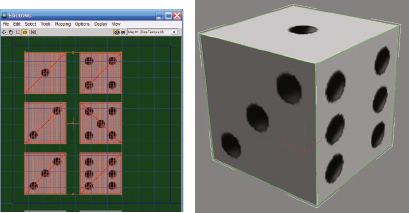
17. Use Move transform to position the other 5 faces over the remaining sides of the die. The result of this exercise should look similar to the following illustration. If you want to see a completed version of this exercise, open the file ch15-02.max.
This was a very simplistic demonstration of the Unwrap UVW modifier to help illustrate how we can control the precise placement of a texture on geometry. Now we’ll apply this feature to an architectural example.
Applying Tileable Textures
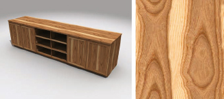
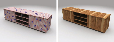
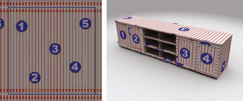
There are numerous applications for the Unwrap UVW modifier in an architectural setting. In this next exercise, we’ll apply the texture shown on the right side of the next illustration to produce the rendering of the furniture shown on the left.
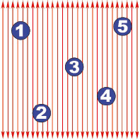
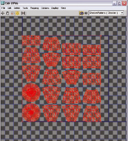
We’ll start with a schematic texture for this exercise to make it easy to identify the various parts of the texture when it’s applied to furniture. Later, we can switch the schematic texture with a real wood texture. The texture shown in the following illustration will represent a typical wood pattern where the direction of the arrows indicates the wood grain and the numbers represent imperfections such as knots or blemishes. Using an image like this is not a suggested workflow for using Unwrap UVW; rather, this texture is used for illustrative purposes.
1. Open the file ch15-03.max. This scene contains a cabinet with the texture shown in the previous illustration applied.
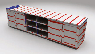
2. Render the Camera view. The result should be the cabinet shown in the left image of the next illustration. The right image shows what the cabinet would look like with the wood texture applied. The large wood grain is intentional so you can see how the same grain continues across several surfaces, which is not desirable. Also, the doors would have a different grain direction on the door panel compared to the door border. Let’s follow a similar workflow as before.
3. Apply the Unwrap UVW modifier to the cabinet.
4. Click the Edit button within the Parameters rollout.
5. In the Selection Modes section of the Edit UVWs dialog box, click on the Face Sub-object Mode icon.
6. In the Selection Parameters rollout of the Modify panel, disable Ignore Backfacing.
7. Press Ctrl+A to select all the faces of the object.
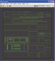
8. From the Mapping menu of the Edit UVWs dialog box, select Flatten Mapping and accept the default values. The result should look like the following illustration. Note that the illustration has the background texture disabled. The toggle for this is the blue and white checkered cube in the top toolbar. Depending on your preference this can be enabled or disabled.
To better understand what the Unwrap modifier has done to our texture so far, let’s render the scene again without adjusting anything more.
9. Render the scene. The result should look like the following illustration.
Scaling and Orienting the Texture
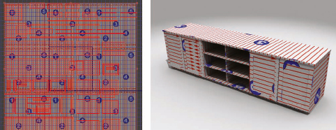
Obviously things don’t look right yet. The texture in the previous illustration appears too large and in some areas is not oriented correctly. Let’s deal with the scale issue first. Look at the left image of the following illustration and notice that every face is packed neatly into the texture space of the Edit UVWs dialog box.
10. Select every face in the Edit UVWs window and scale them approximately 300%. You can scale over and over again until the texture resolution in the viewport appears the way you want it.
11. Render the scene. We can see that by scaling up the faces in the Edit UVWs dialog box, each face is allowed to see more of the texture, effectively making the texture smaller on every face. The difficulty we have now is that the orientation of the arrows is wrong in some areas. The door panels should have the grain run vertically instead of horizontally.
12. With the Edit UVWs dialog box open, select each of the 4 door panels in the Camera view. Notice that the 4 faces become highlighted in the Edit UVWs dialog box, as shown in the left image of the following illustration.
13. Click the Rot. +90 button in the bottom right corner of the dialog box. Now the four door panels will be oriented 90 degrees from their original orientation, as shown in the right image.
Notice that the faces in the Edit UVWs window overlap other faces. This is perfectly fine since the faces are independent of each other. This means that we can move them wherever we want to position them on the texture. So if we wanted to place numbers on each door, we can move and scale only those faces we want to adjust. The next illustration shows a simplified Edit UVWs window with a texture, so you can see the resulting render based on the placement of the faces. Notice in the left image of the following illustration that the door panels have been centered over the numbers in the texture and the resulting rendered image on the right. We can adjust any face this way.
14. Deselect the 4 door panel faces you currently have selected and reselect just one of them.
15. Move the selected face so it’s positioned over any number 1 shown in the background of the dialog box.
16. Repeat the previous step with the other 3 door panels so each door panel is positioned over a different number, as shown in the left image of the following illustration.
17. Render the Camera view. The result should now look similar to the right image of the following illustration.
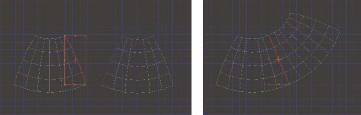
The only thing we need to adjust now is a few of the edges of the doors. The wood grain should run vertically for the left and right edges of each door and horizontally for the top and bottom edges. If you look closely in the viewport or the previously rendered image, you will see that the top and bottom edges of the each door show that the wood grains are oriented horizontally, as they should be. The left and right edges of each door, however, show the grains oriented horizontally when they should be vertical. We simply need to select the left and right edges of each door panel and rotate them 90 degrees in the Edit UVWs dialog box.
18. In the Camera view, select the faces that make up the left and right edges of the 4 doors. You can also just select them in the Edit UVWs dialog box if you want.
19. Right-click the mouse inside the Edit UVWs dialog box and from the quad menu select Detach Edge Verts. This separates the left and right edges of each door panel from the top and bottom edges. Now you can move the selected faces elsewhere without bringing the other faces along in the process.
20. Click the Rot. +90 button to rotate the selected faces 90 degrees. You could also move them to another location on the background image; however, that is not really necessary here.
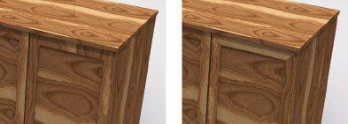
21. Render the Camera view. The following illustration shows a before and after result of this adjustment with a proper wood texture applied. If you would like to see a completed version of this exercise shown in the next two illustrations, open the file ch15-04.max.
By going through and adjusting the scale and position of the faces within the Edit UVWs window we can take a simple texture and make it go a long way.
As an additional note, this previous exercise required a tileable texture. If we didn’t have a tileable texture we would see noticeable and usually distracting seams in many of the faces of the furniture. Textures that don’t tile should follow the steps we discussed previously when we textured the die. Run through this procedure a few times on your own to make sure you get acquainted with the process before trying to map complex organic shapes with curvature. The next exercise demonstrates this kind of mapping and provides a good introduction with a simple sphere.
Mapping Complex Geometry
The Unwrap UVW modifier contains numerous tools to allow the mapping of complex geometry with numerous convex and concave surfaces. Some are outside the scope of this book but I would urge you to look deeper into the Pelt, UVW Unfold, and Sketch Vertices tools. In the following exercise, we look at mapping a sphere to introduce the process of mapping curved surfaces.
1. Reset 3ds Max.
2. Create a sphere of any size in the Perspective view and convert it to an Editable Mesh. Converting to an editable mesh is necessary for one of the next steps.
3. Within the Utilities panel, click on the More button to open a list of available utilities.
4. Select the UVW Remove command. This loads a utility that can strip geometry of both its material and UVW mapping. The stripping of UVWs only works on collapsed editable meshes, which is why collapsing to an editable mesh was necessary. When primitives are created, mapping coordinates are automatically created. In the case of this sphere, a spherical mapping type is applied. Because of this, when a Unwrap UVW modifier is applied, the way the faces are spread out in the Edit UVWs dialog box will be different from the way they would be spread out if no mapping were applied. Stripping the sphere of its mapping coordinates will make it easier to perform the remainder of this exercise.
5. Click the UVW button.

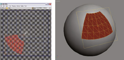
6. Apply the Unwrap UVW modifier to the sphere and open the Edit UVWs dialog box. You will see the sphere has a simple planar map evident from the top down view in the Edit UVWs window. What we need to do is select a group of adjacent faces.
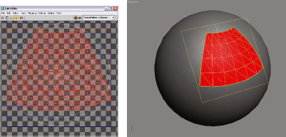
7. Switch to Face Sub-object Mode and make a selection similar to the one shown in the next illustration. Notice that as you select the faces, a planar gizmo appears and orients itself to the average of all the normals of the selection. This gizmo is the Quick Planar Map gizmo and allows you to take a planar “snapshot” for mapping at any time. This will make a little more sense in just a moment.
8. Scroll down within the Unwrap UVW modifier and open the Map Parameters rollout. Here you’ll find the Quick Planar Map button. Once you click this, it will create a planar map based on your selection.
9. Click on the Quick Planar Map button. Note that if the Preview Quick Map Gizmo is not selected you will not see the gizmo but it will still function. Notice also that there is an Averaged Normals switch automatically selected. This is what causes the gizmo to be created based on the average normal of all the selected faces. By clicking one of the X, Y, or Z options above this, you can disable that option to create a gizmo as we did, and instead create one projected along the X, Y, or Z axis. To see what this really means, try enabling the X option and then switching your view to a Right view. When you do, you will see the selected faces appear the same in the Edit UVWs dialog box as you see them from a Right view. Regardless, for difficult geometry, it is a good idea to leave this option enabled.
Now once the button is pressed, you’ll see the selected faces become mapped as per the gizmo.
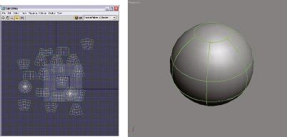
Continue selecting faces and making planar maps until all the faces have been mapped. Notice that the individual maps are delineated by the green lines, as shown in the next illustration. These are called map seams. The mappings in the left image have been moved around in the Edit UVWs window to display how many separate maps were created. We will now pack these nice and neat in the Edit UVWs window.
10. Select all the faces in the Edit UVWs window.
11. From the Tools menu in the Edit UVWs dialog box, select Pack UVs. Accept the defaults and watch how 3ds Max neatly arranges all the mappings into the defined texture space.
12. Maximize the Edit UVWs dialog box so it takes up as much of your screen as possible.
At this point we can take a screen capture and load it into a photo editing program like Photoshop and start painting or editing a custom texture using the various mappings we created as a perfect guide. Or we can use any existing texture and move and align the elements within the Edit UVWs window to place the texture as we see fit. To create a custom texture in Photoshop, do the following:
• Make sure the dark blue rectangle in the Edit UVWs dialog box is completely visible.
• Press Alt+Printscreen on the keyboard.
• Create a new document in Photoshop and paste the screen capture (Ctrl+V) into the new Photoshop document.
• Change the image size and resolution to a desired size.
• Create a new layer and start painting using the faces represented in the Edit UVWs screen capture as a guide.
• Save the texture to an image format you like, create a material using the new texture you’ve created, and apply it to the geometry.
One last thing to look at is welding UVW mappings together. As you see in the previous illustration, we have 20 individually mapped entities in the Edit UVWs dialog box. This can be problematic since they are all mutually disjointed and we will definitely see a seam in the mapping. We can weld these together by entering Edge Sub-object Mode and selecting the edges of one mapping.
13. Make sure the Select Element option is turned off and select the Edge Sub-object Mode icon.
14. Select an edge on any of the mappings in the Edit UVWs dialog box, as shown in the next illustration.
15. From the Tools menu in the Edit UVWs dialog box, select Stitch Selected and accept the defaults. Likewise, we can separate these by choosing Tools > Break, which will break the mappings apart.
Summary
The Unwrap UVW modifier is an amazing and robust tool that allows us to create the most complex of texture mappings. This chapter only scratched the surface but introduced some key concepts you can carry forward to learn upon. I would recommend looking at some tutorials on texturing characters since these will delve deeper into the toolset. Often, inspiration comes from the most unlikely sources, and texturing characters can give you practice in texturing the most demanding geometric shapes. For continued self-help with this modifier, try to start using the Unwrap UVW modifier in the course of your normal work or training, instead of always relying on the UVW Map modifier. Using the Unwrap UVW modifier on simple geometry that you would normally apply a standard UVW Map modifier to will force you to think of the process and get your hands dirty.