
CHAPTER 5
Creating Roofs
AFTER WALLS ARE ERECTED AND windows and doors are in place, the next logical object to create for a building is the roof. If you rely on BIM software to create your roofs, you can literally create a roof with a few clicks of the mouse, but while this can seem like an appealing feature for this type of software, creating complex roof structures with BIM software can often be more of an annoyance than a pleasure. This is because of the somewhat limited capability of today’s software to try to interpret what you try to direct. While the methods described in this chapter will not afford you the opportunity to create a roof in literally just a few seconds, they will allow you to create one with ease and precision.
In this chapter, we’ll start by looking at different ways to create the generic roof structure, meaning the individual surfaces defined by a roof plan, and then we’ll focus on the different finishes you will typically need to apply to your roofs. With the exception of the most simplistic flat roofs, all 3D roof models must start with a roof plan. If you are fortunate enough to have worked in an architectural office creating roof plans in 2D you will undoubtedly find less difficulty with the creation of roofs in 3D because half of the challenge is interpreting what you are looking at, even when the roof plan is drawn correctly and all elevations are present. Oftentimes, roof plans are not available at the time your work must begin, and while you can certainly insist on receiving a solid roof plan from your client before you begin working, you might be asked to create one yourself when one doesn’t yet exist. Not being able to create a roof plan can be a handicap, but not being able to interpret one is a show-stopper. This chapter does not attempt to teach the understanding of roof plans, but rather how to turn one into a 3D model.
Terminology
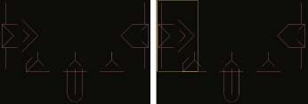
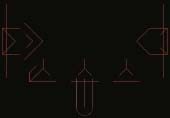
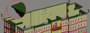
Before beginning a discussion on the creation of 3D roofs, an overview of some key terminology is in order. The following is a brief description of the most important roof elements you need to know when working with architectural drawings. They are almost always referenced at some point in a set of architectural drawings. Figure 5-1 illustrates each of the important elements listed.
Key Elements
Eave – the part of a roof that overhangs a wall
Soffit – the underside of an eave
Fascia – the vertical, outermost edge of an eave
Ridge – the horizontal high point between two sloping roof surfaces
Ridge cap – the weather proofing cover that sits on top of a ridge to seal two adjacent slopes
Pitch – the slope of a roof usually defined by a rise over run (rise/run)
Rise/Run – the ratio between vertical rise and the horizontal run of a roof
Hip Roof – a roof that has a sloping end and sloping sides
Gable Roof – a roof that has slopes only on its sides and forms a triangular-shaped wall at its end
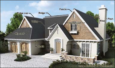
Figure 5-1. Important roof terminology.
The Generic Roof Structure
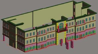
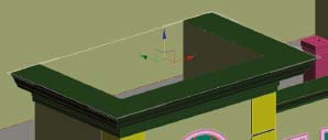
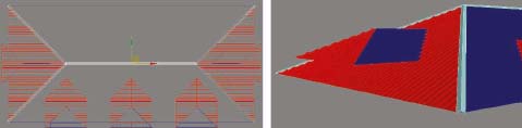
Before you can apply a roof material in your scene, you have to first create a generic roof structure. This is simply the individual polygons, as shown on the left side of Figure 5-2, on which a roof material is placed, such as the concrete tiles shown on the right side.
Besides BIM software, there are two primary methods with which to create this generic roof structure. You can either use the existing CAD roof plan linework to create the necessary polygons and then move those polygons to the proper height, or you can reverse engineer the roof plan linework using the existing 3D walls you’ve already created. As a matter of preference, always prefer to reverse engineer a roof plan, even when one already exists, but both methods will be discussed here along with their benefits and drawbacks. For the sake of familiarity, we will continue working with the same building that was used in the last few chapters.
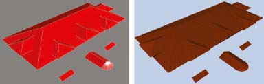
Figure 5-2. The polygons that make up the generic roof (left) and the concrete tiles placed on the roof (right).
Working with an existing roof plan
Turning an existing roof plan into a generic 3D roof structure is a rather simple process of creating a series of closed splines, either in AutoCAD or 3ds Max, and turning those splines into editable mesh or editable poly objects. As mentioned throughout this book, AutoCAD is far better at line editing than 3ds Max, so if you can prepare this roof linework in AutoCAD, I highly recommend it. Just like every other area of modeling, you should spend a little time analyzing the roof plan linework to ensure that the roof plan is correct and matches the elevations, and that the linework is clean. By clean, I simply mean that lines meet with coincident endpoints, horizontal lines are perfectly horizontal, vertical lines are perfectly vertical, 45-degree lines are perfectly 45-degrees, and so on. The linework for the exercises in this chapter is already cleaned per the guides in Chapter 2 so we can avoid this initial cleaning process. As with previous chapters, the same basic steps outlined in AutoCAD can be performed with imported linework in 3ds Max.
1. Open the AutoCAD file ch05-01.dwg.
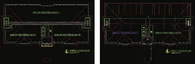
2. Move the roof plan linework so that instead of being positioned on top of the 3rd floor plan, as shown on the left of the next illustration, it is instead positioned on top of the 1st floor plan, as shown on the right. A quick way to do this would be to enable endpoint snaps, select and isolate the layer the roof plan is on (Roof-plan), select all the roof linework, turn all layers back on, execute the Move command, use the P option to select all previously selected linework (i.e., the roof linework), select any corner on the 3rd floor plan and select the same corner on the 1st floor plan to complete the move.
3. Isolate the Roof-plan layer so we can work on creating new linework without having to see through the existing floor plan linework. You should see only the roof plan linework shown on the left side of the next illustration.
4. Create a new layer called 0-Roof, set the layer color to red, and make this the current layer.
5. With endpoint snaps enabled and using the right image in the next illustration as a guide, draw a closed pline in the shape of a triangle from the top-left corner of the main roof to the apex, down to the bottom-left corner of the main roof, and back to the starting point. This pline must be closed in order to be converted to an editable mesh or poly in 3ds Max.
6. Repeat the last step by creating closed splines for each individual roof surface, as shown in the next illustration. Do not create any plines for the first floor overhang roof because we will create this particular roof type with a different method that suits this type of roof better.
7. Save this file.
8. Switch to 3ds Max and open the file ch05-01.max. This scene contains all of the walls, windows, and doors that would (or should) be completed by the time a roof is created.
9. Using the AutoCAD DWG file type, import the 0-Roof layer from the drawing you just saved, and derive objects by Layer. You can also import this layer from the file called ch05-02.dwg. Since the roof plan was drawn on the home grid (i.e., an elevation of 0), the imported linework lies at the base of the walls, as shown in the next illustration.
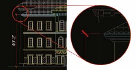
10. Switch back to the AutoCAD and take a distance measure from the ground to the very top of the main roof’s fascia. The distance should be measured at 40’-2”, as shown in the next illustration.
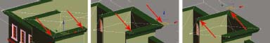
11. Return to the 3ds Max scene and elevate the roof linework 40’-2”. When you do, notice that the corners of the main roof plan linework do not perfectly lie on the corners of the 3D fascia. This will almost always be the case unless you reverse engineer a roof plan, as we will do in the next exercise. The solution at this point would be to enter vertex sub-object mode and individually adjust the location of each vertex. The main problem with this approach is that it results in an inaccurate roof plan, meaning that ridges and valleys will not exist perfectly between their respective eaves and roof pitches do not perfectly match what is shown in the elevations. This does not mean that this inaccuracy is unacceptable. In fact, it would be nearly impossible for the viewer to notice this type of inaccuracy.
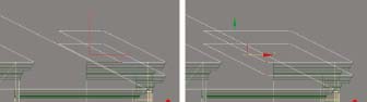
12. With endpoint snaps enabled and with the Layer:0-Roof object selected, enter Vertex sub-object mode and move the 4 corner vertices of the main roof plan so they snap to the 4 corners of the fascia, as shown in the next illustration.
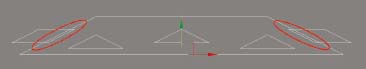
13. Select the 12 vertices that make up the 2 hip roofs on each side of the building, as shown in the next illustration.
14. Using endpoint snaps, move all 12 vertices to their proper height by snapping any single vertex to its exact proper location, as shown in the next illustration. Having done this, 2 of the 12 selected vertices on these 2 hip roofs are now properly positioned; the one you snapped to and the one next to it. Now, let’s move other vertices on these two hip roofs to their proper location.
15. Select the 2 vertices shown selected in the left image of the next illustration and snap them to their proper location using the corner vertex. Repeat this step with the other 2 sets of 2 vertices shown in the middle and right images. When this is done, all of the outside (eave) vertices will be properly positioned.
16. Select the 12 vertices that make up the 2 outside hip roofs on the front of the building, as shown in the next illustration.
17. Snap these 12 vertices to their proper height by snapping one vertex to its exact proper location.
18. Repeat the earlier step of snapping the remaining outside (eave) vertices to their exact proper location.
19. Select and position the 6 vertices that make up the front center hip roof and position them as you have all the previous hip roofs thus far, and as shown in the next illustration.
Now that the eave of each roof is located properly, the last step in creating the generic roof structure is to elevate the vertices that represent the ridge of each roof.
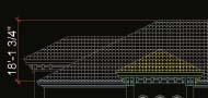
20. Switch to the AutoCAD file and measure the distance from the eave of the main roof to the ridge of the main roof, as shown in the next illustration. This distance should be measured as 18’-1.75”. This is the distance the ridge vertices of the main roof need to be elevated.
21. Return to the 3ds Max scene, or if you wish to continue from this point with an already prepared scene, open the file ch05-02.max.
22. Select the 2 vertices that represent the ridge of the main roof and elevate these vertices 18’-1.75”.
23. Switch back to the AutoCAD file and measure the distance from the eave of one of the side hip roofs to its ridge. This distance should be measured as 6’-6.25”. This is the distance the ridge vertices of the side hip roofs need to be elevated.
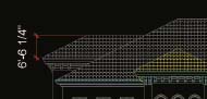
24. Return to the 3ds Max scene, select the 4 vertices that represent the 2 ridges of the 2 side hip roofs and elevate these vertices 6’-6.25”.
25. Switch back to the AutoCAD file and measure the distance from the eave of one of the outer hip roofs on the front of the building to its ridge. Just like the last roof, this distance should be measured as 6’-6.25”. In fact, because every one of the small hip roofs is exactly the same width and has the same pitch, they have the same change in rise.
26. Elevate the ridge vertices of all remaining roofs 6’-6.25”. Once this is done, all of the vertices of the generic roof structure will be in place.
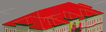
27. Add the Edit Mesh or Edit Poly modifier to the roof object. The linework is converted into a renderable 3D roof structure, as shown in the next illustration.
The generic roof structure might appear at first to be complete; however, there are a few remaining problems.
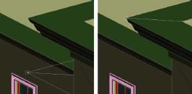
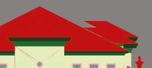
28. Switch to Front view and notice how the side hip roof runs into the main roof structure, as shown in the next illustration. Because of this, there is no gap between the side roofs and the main roof.
29. Switch to Left view and notice how the front hip roofs do not run into the main roof structure, as shown in the next illustration. Because of this, there is a gap. This is a very common occurrence that is often caused by inaccuracies in the roof plan and/or elevations, or conflicts between them.
30. While in Left view, select and move the vertices that make up the back side of these hip roofs so they run into the main roof, as shown in the next illustration.
31. Close sub-object mode. It is important to note at this point that while you can certainly place these vertices well within the main roof, to create a roof on which you intend to place 3D tiles, I highly recommend positioning these vertices so they lie right on the surface of the main roof. This is so that when you place the 3D valley caps at these intersecting surfaces, you have vertices to snap to. Otherwise, placing valley caps can be very tedious.
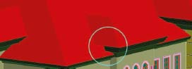
The roof structure is now complete and ready for a roofing material. However, there is one final problem with the roof that needs to be corrected. The fascia on the 2 outer hip roofs on the front side of the building do not run into the main roof structure, as shown in the highlighted area of the next illustration. This is because these objects were created with the loft feature and were once part of the walls they rest on. The fascia was detached from the wall lofts but because the walls did not run any farther into the center of the building, neither did the fascia. The simple fix is to adjust the end vertices of the fascia objects so they do run into the roof like the rest of the fascia.
32. Select the Bldg-Fascia object and enter Vertex sub-object mode.
33. For both of the roofs in question, select the vertices that make up the back side of the fascia and move them into the main roof, as shown in the next illustration.
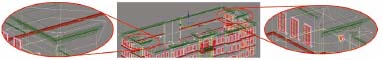
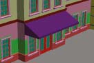
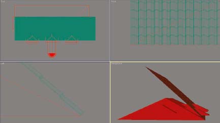
On the front of the building are 2 more roof types that need to be created. The small roof highlighted on the left side of the next illustration can be created quite easily by extruding a closed spline, and the overhang roof highlighted on the right can be created with a loft. For the purpose of this exercise, the necessary linework has already been prepared.
34. Merge the 3 objects inside the file ch05-roof_linework.max into your current scene. These objects represent the linework needed to create the 2 new roof types just mentioned.
35. Select the object Bldg-Roof-Small and extrude it 20’-0”. This is the width of the small roof shown in the next illustration. Once this extrusion is made, you can add detail to the roof as you like, but this roof is complete per the details shown in the elevations. In a moment, we’ll add roof tiles to this and the other roofs.
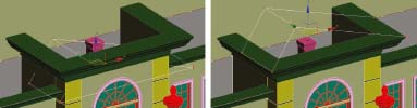
36. Select the object Bldg-Roof-path and create a loft from it using the object Bldg-Roof-profile as the profile.
37. Reduce the Shape Steps and Path Steps to 0. When you do, you should see a loft created as shown in the next illustration. This technique is very handy for creating these types of roofs because you can create the actual roof structure at the same time you create the beams that support the roof. The only problem is that no matter how precise you try to make your path and profile, you will always have a gap at the ridge of the roof or an overlap where one end of the loft wraps itself, as is the case here. A quick fix is to weld the problematic vertices.
38. Add the Edit Mesh modifier.
39. Go to Vertex sub-object mode and select the vertices at the front apex of the roof, as shown on the left side of the next illustration.
40. Weld the selected vertices using a threshold distance of 1’-0”. This causes all of the vertices to weld into 1 vertex, as shown on the right side of the next illustration. When this is done, the roof appears normal.
41. Rename the loft Bldg-Roof-Overhang. As mentioned in earlier chapters, renaming objects after they are structurally completed or after materials have been applied is a good way to keep track of which objects are finished and which objects still need work.
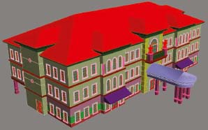
42. Save your scene for use in the third exercise in this chapter. The completed roof should look like the next illustration. If you wish to see the completed scene at this point, open the file ch05-03.max. This is the end of this exercise.
Reverse engineering a roof plan
Another alternative to creating a roof as outlined in the previous exercise is to reverse engineer the roof plan. This simply means that instead of using the roof plan linework you receive and building your roof directly from this linework, you instead build or modify a roof plan using the already created walls as a guide.
In the following exercise, we will start with the same scene we started the 1st exercise in this chapter with, but instead of using the roof plan as is, we will create new linework in 3ds Max, export that linework to AutoCAD, create or modify an existing roof plan, and import this new roof plan back into 3ds Max. The result will be a roof plan whose endpoints are, without a doubt, located precisely where they need to be. This method is not always necessary, but there are a few reasons why it might be.
Roof plans are not always available at the time we begin our work, so if you can create linework to help guide the creation of an accurate roof plan as just described, then reverse engineering might be the best option. Also, many roofs are extremely complicated and quite difficult to understand, even for experienced 3D artists. When this is the case, creating linework from existing 3D walls can serve as a useful visual aid to ensure that your roof plan is drawn with precision, and that it’s accurate in the first place. For complicated roofs, it’s not unusual for experienced drafters or even architects to trim or extend a line in the wrong place. Creating linework from existing 3D walls has a way of facilitating the understanding and modification of an existing roof plan. Finally, if you have any desire to build your roofs with accuracy, meaning no irregularities such as gaps between the roofs and fascia, then you are undoubtedly going to have to modify your 3D roof once it’s created, to make endpoints on the roof match the endpoints on the fascia. Therefore, doing this step prior to roof creation doesn’t really add any work and if it can facilitate the entire process it is a worthwhile alternative.
1. Open the 3ds Max scene, ch05-01.max. This is the same scene we used in the previous exercise.
2. Create a closed spline in the shape of rectangle whose endpoints are snapped to the 4 topmost corners of the main roof, as shown in the next illustration.
3. Create another 4-point rectangle on the very top of the fascia found on the center roof of the front elevation.
4. Repeat the last step with the other remaining roofs. There should be a closed 4-point spline created at the very top of each individual fascia. These splines will now be imported into AutoCAD and compared with the roof plan provided for this project. If you do not have Auto-CAD, you can still perform the same basic steps in 3ds Max using the roof plan you imported into 3ds Max.
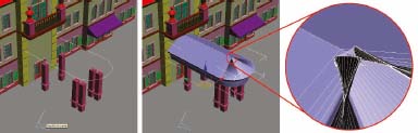
5. Select all 6 splines and export them as a 3ds file.
6. Switch to AutoCAD and open the file ch05-02.dwg.
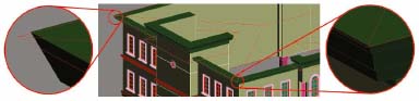
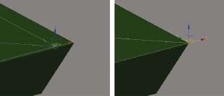
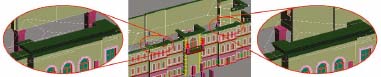
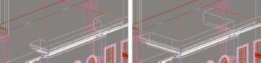
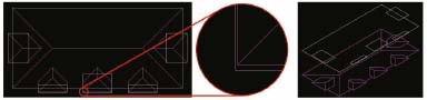
7. Import the 3ds file you just created. When you do you should see the 6 splines come to rest on top of the existing roof plan, as shown in the far left image of the next illustration. However, if you zoom in closely to any of the roof corners, you will see that there is a substantial misalignment between the linework you imported and the existing roof plan. Furthermore, if you change to a perspective view, you will see that the imported linework is positioned at a much different elevation than the existing roof plan, as shown in the far right image in the next illustration. The linework you just imported exists at the exact proper location and can now be used to correctly modify the position of the existing roof plan. If you didn’t have a roof plan at all, this would also be a great way to start. Because of the great line editing capabilities of AutoCAD, creating or modifying a roof plan like this is a fast and efficient way to work. You can, of course, do the exact same thing without the use of AutoCAD, but you will certainly take longer to do it.
8. Correct the original roof plan using this imported linework as a guide.
9. Once the existing roof plan linework has been corrected, import the corrected linework into 3ds Max and create your roof as outlined in the previous exercise. This is the end of this exercise.
Applying Roofing Materials
Most roofs we work on in the 3D visualization world can be classified as one of three types: tile, standing seam, or shingle. Each of these 3 categories also contains a wide array of subcategories that might sometimes seem more varied than certain species of trees. For example, in the category of tile, you might be asked to provide clay tile, Spanish tile, barrel tile, metal tile, concrete tile, cement tile, ceramic tile, and so on. The list of standing seam and shingle roof variations is just as dramatic. But while we should always strive to give our clients a great product, this doesn’t mean that we need to provide exactly what is specified in the architectural drawings. For example, when a tile roof is specified, we certainly need to provide a tile roof. However, when the drawings call for Spanish tile, we will almost always be able to use a Straight Barrel style or a Mediterranean style or anything similar.
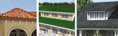
Figure 5-3. An example of a tile, standing seam, and shingle roof.
The application of the three different types of roof materials shown in Figure 5-3 requires 3 completely different approaches. The final section of this chapter discusses these 3 different approaches.
Tile Roofs
In the 1st decade of 3D visualization, very few artists attempted to place 3D tiles on a roof, relying instead on textures. The difference in realism between the two is profound, and today textures are simply unacceptable in most projects. While 3D tiles can dramatically increase the polygon count in a scene, there are a few things you can do to minimize the count and keep viewport refresh rates up and render times down.
Placing 3D tiles on a roof requires a good amount of time and until a ground-breaking plugin or script comes along, there’s really no way around it. As mentioned, the exact style you decide to use is usually irrelevant and what’s more important is how you place the tile. To facilitate the placement, you should create a 3ds Max scene that contains a large sample of your tile that can be placed and copied over the length of your various roof surfaces. Figure 5-4 shows such a sample. The entire sample is comprised of just one object and that object contains a multi-sub-object material with 4 different sub-materials. Incidentally, many tile roofs use only 1 color throughout the entire roof, but by building a sample such as this with several different sub-materials applied, you can decide at any time whether to use just 1 or several different colors.
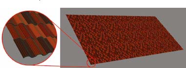
Figure 5-4. A large expanse of 3D tile to be placed on the various surfaces of a roof.
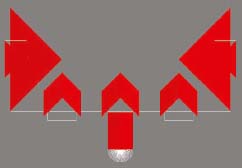
Since 3D tiles can have a detrimental effect on system resources, one of the things you should always make sure you do is use tile that does not have a back to it. For example, Figure 5-5 shows the same tile sample as shown in Figure 5-4, only this time from behind. Notice that the only faces visible from behind are the edges of the tiles. Placing polygons on the backside of this type of roof will essentially double the polygon count of the roof and would be a complete waste because these polygons would never be visible.
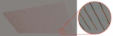
Figure 5-5. The tile sample shown in Figure 5-3 as seen from behind.
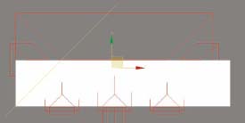
To place 3D tiles on a generic roof structure efficiently ensure that the pivot point of your tile sample is located at the very bottom edge of your sample, as shown in Figure 5-6. This allows you to place your sample at the very edge of your roof and then rotate your sample so it never has to be repositioned. If you align the bottom of your tiles to the edge of the roof but don’t place the pivot point at the bottom of your tiles as well, when you rotate your tiles to match the roof pitch, the bottom of the roof will no longer be aligned to the edge of the roof.
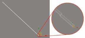
Figure 5-6. Aligning the pivot point of a tile sample to the very bottom of the sample.
At this point, let’s run through an exercise that demonstrates the placement of 3D tiles on the generic roof structure created during the 1st exercise of this chapter.
Placing 3D Roof Tiles
This exercise demonstrates how to place 3D tile on a generic roof structure.
1. Open the 3ds Max file, ch05-generic_roof.dwg. This scene contains only one object; the generic roof structure created in the 1st exercise of this chapter.
2. Merge in the 3 objects from the file 3D_tile_roof_sample.max. One object is the large roof sample, and the other two objects are the ridge and valley caps that will be placed on the generic roof.
3. Hide the objects named Ridge Sample and Valley Sample.
4. Select the Tile Sample object and align the very bottom left corner of the object (as seen from Front view) to the very bottom left edge of the main roof. The result should look like the next illustration. Since this object has such a high polygon count, using only one viewport or disabling unnecessary viewports can speed placement.
5. If you have not already done so, switch from a 4-viewport layout to a single viewport layout.
6. Switch to Left view and zoom to the extent of the object.
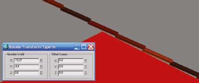
7. Rotate the object about the Z-axis (as seen from Left view) until the tiles are placed squarely on the front surface of the roof, as shown in the next illustration. Zooming in to the apex of the main roof will help place the tiles properly. The tiles need to be rotated exactly -15.27 degrees (about the Z-axis using Offset:Screen mode or the X-axis using Absolute:World mode) to be perfectly positioned, so you can use this value if you want.
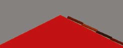
8. Enter Element sub-object mode and delete all of the tiles from the apex of the roof and above.
10. Select and isolate the Bldg-Roof object.
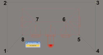
11. Draw a closed spline with 8 vertices as shown in the next illustration. This spline is going to be used to trim away that part of the Tile Sample object that overlaps the front surface of the main roof. Therefore, it needs to be drawn accurately with points 5 through 8 being as close as possible to the corners of the roof surface in question. That being said, it can be a few inches off because we are going to place a roof cap over the tiles. You can always just snap to these vertices; however, you will then have to move them later so they are all at the same elevation. I prefer to simply zoom in and ‘eyeball it’.
12. Extrude this object 100’. Since the roof tiles are elevated about 40’ above the home grid, this causes the resulting extrusion to run directly through the tiles.
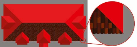
13. Exit Isolation Mode and use the Boolean>Subtract feature to cut away the excess tiles, as shown in the next illustration. With an object that contains as many polygons as the roof tile object, performing the Boolean operation can take 2 or 3 minutes, depending on the speed of your computer. Many users prefer the ProBoolean feature; however, one of the downsides to this feature is that it can take far longer to finish than the Boolean operation. For an object like the roof tiles, the wait may be extremely long.
As an additional note, you can add the Edit Mesh or Edit Poly modifier to the Tile Sample object and create a slice plane that cuts through the tiles directly where the tiles need to be trimmed, as shown in the next illustration. Once the tiles are sliced, you have to manually select and delete all the unnecessary tiles. The biggest problem with this method is the sluggish rate at which 3ds Max refreshes your display, which of course is caused by displaying such a high poly object. If you use this method you will have to do a lot of panning and zooming, and the result can be a painfully slow trimming operation. You can always use a temporary aid such as Fast View Nth Faces so that only every Nth face has to be refreshed, but I still prefer the Boolean technique over any other.
Now that the first roof surface is finished, you can quickly and easily mirror these first tiles so they are duplicated on the back side of the main roof. Depending on your render engine and your workflow, you might want to make a decision at this point, whether or not to create the mirrored object as a copy or an instance. If you create an instance, then of course your file size won’t increase. I would suggest doing this at the very least. You can also create an XRef of your roof tiles so the data is stored in another file. If you use mental ray or V-Ray, I would suggest creating your entire roof as one object and turning that object into a proxy. This will cause the roof tile data to be stored in a separate file (like an XRef) and cause the roof tiles to be rendered as dynamic geometry. This means that the data is loaded and unloaded on the fly during the rendering process rather than being all loaded at once at the start of the rendering and staying in memory until the rendering is complete, which is how static geometry is treated. The result is that you can render much larger scenes without running out of RAM so easily.
At this point, there is no need to continue with the placement of tiles in this exercise because doing so would simply be repetition of the commands already used. Once all of the various roof surfaces have been finished with tiles, we would need to unhide the Ridge Sample and Valley Sample objects and place each of these objects in the same manner outlined in this exercise thus far.
Standing Seam
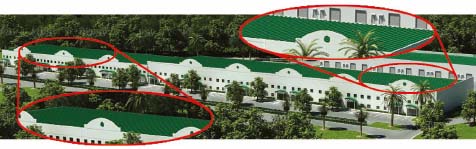
Unlike a tile roof, which requires the meticulous and time-consuming placement of individual tiles, standing seam roofs are relatively quick and simple to create and are usually best created by carving detail into the generic roof structure. In the real world, this kind of roof comes in a seemingly endless variety of types, just like the variety found in tile roofs. However, just like tile roofs, you can usually get away with using one type and not worry about duplicating the exact detail found in a real metallic roof. For example, Figure 5-7 clearly shows a standing seam roof; however, unless you were very close to the roof, you would never be able to tell which of the varieties shown on the right are being used. Because of this, we can create these types of roofs very quickly using a very simple technique.
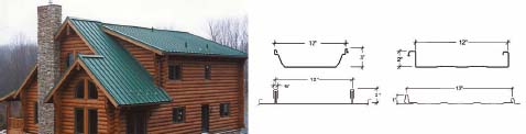
Figure 5-7. An standing seam roof with an indistinguishable seam style.
Just like the tiles on a roof shouldn’t be represented by a texture, standing seams shouldn’t as well. This is even truer when you consider how quick and easy it is to physically create the seams, as compared to placing 3D tiles. To create the seams in a roof, simply use the Boolean>Cut>Split feature to create cuts in the roof and the Edit Mesh or Edit Poly modifiers to elevate the newly created polygons. The following exercise demonstrates this.
Creating standing seams in a roof
In this exercise, we will start once again with the same roof we started with in the last exercise. Instead of placing 3D tiles on the roof, this time we will cut seams into the various roof surfaces and push those new polygons upward to create the look of standing seams.
1. Open the 3ds Max scene, ch05-generic_roof.max. This is the same scene we used in the previous exercise. The only object in this scene is the generic roof structure we created in the first half of this chapter.
2. Select the object Bldg-Roof, go the Modify panel and enter Polygon sub-object mode. Before we can cut the seams into the roof, we have to separate the polygons that are going to have the seams running in different directions. We need to create 2 separate objects from the roof object. One will contain all the polygons where the seams run vertically (as seen from Top view) and the other will contain all the polygons where the seams run horizontally.
3. Select all of the polygons that will have seams running horizontally, as shown in the next illustration.
4. Detach these polygons and name the object Seams-Horizontal.
5. Close sub-object mode and give the current roof object a new color to help distinguish its polygons from the polygons you just detached. You should have something similar to what’s shown in the next illustration.
6. In Top view, create a box of any size directly above the roof (as seen from Top view), as shown in the next illustration.
7. In the Modify panel, change the Length to 0’-3”, the Width to 200’-0”, and Height to 100’-0”. A length of 3” means that the seams will be 3” wide. A width of 200’ simply allows the box to span the roof, and a height of 100’ simply means that the box will run up through the roof and allow us to perform the Boolean>Cut>Split operation.
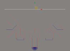
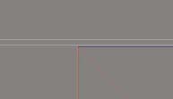
8. Move the box so it is just beyond the back side of the roof, as shown in the next illustration.
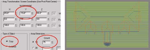
9. In the Tools menu, select Array and use an Incremental Y Move of -1’6” and a 1D Count of 75. Enable the Copy option as the type of object to be made. This makes 75 copies of the box in the negative Y direction, as shown on the right side of the next illustration. A value of 1’-6” was used because that is going to be the distance between seams.
10. Attach all the seams together so they become one object.
11. Select the object called Seams-Horizontal and in the Create panel select Geometry Compound objects > Boolean.
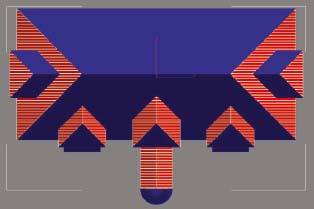
12. Select the Cut>Split option, click the Pick Operand B button, and click on the horizontal boxes you just attached together. The resulting object should have new edges created, as shown in the next illustration.
13. Add the Edit Poly modifier, go to Polygon sub-object mode and extrude the selected polygons 3 inches. A great characteristic of the Boolean>Cut>Split feature is that cut polygons are automatically selected when you go to polygon sub-object mode. The ProBoolean feature does not do this, which is why it shouldn’t be used in this way.
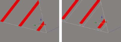
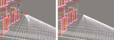
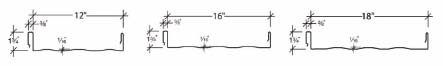
A very important consideration before creating the 1st box is how wide the seams are going to be and how far apart they should be placed. As the next illustration shows, there are 3 standard distances that U.S. manufacturers use between seams in a roof; 12”, 16”, and 18”.
But unfortunately, due to the limitations with computer displays, the appearance of a standing seam roof is negatively affected by the parallelism of the seams when viewed at a low angle or too much from the side. In the next illustration, you can see that the warping affect of the seams increases toward the left because the viewing angle is increasing. Because of this, it is usually beneficial to increase the thickness of the seams as well as the distance between them. In the real world, most seams are barely 1-inch thick, and as shown in the previous illustration, the largest distance between seams is usually 18 inches. This doesn’t mean that you can’t significantly increase these amounts to reduce the warping affect. As we have done in this current exercise, we made the thickness of the seams 3 inches to make the seams appear more substantial. Otherwise, they might appear extremely thin and unnatural when seen from a reasonable viewing distance. In this current exercise, I elected to keep the spacing between the seams at 18 inches because this roof would not be viewed from hundreds of feet, or from such an angle that would exacerbate the warping effect. With very large roofs viewed from a great distance or at poor angles, I have used spacing as much as 5 feet. In many cases, the viewer simply cannot tell that this has been done, and as I say several times in this book, it is usually far better to make your visualizations look good rather than accurate. This does not mean you shouldn’t be accurate when accuracy is needed. It simply means accuracy is not always needed or beneficial.
The seams for the remainder of the roof surfaces should be created in the same manner outlined thus far. Once these seams are in place, you can move on to the final step in the creation of your roof. The final step is the creation of ridge and valley caps. The process is fairly straightforward and uses the Sweep modifier to create all of the caps from paths and profiles. For the sake of simplicity, we will only create ridge caps for the main roof.
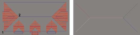
14. In Top view, and with endpoint snaps enabled, draw a line from the bottom left corner of the front roof surface to the apex of the roof, as defined by the numbers on the left side of the next illustration.
15. Draw 3 additional lines for the other 3 corners of the main roof and draw a 5th line from one end of the ridge to the other. The direction in which you draw your lines does not matter. The results of the 5 lines you draw should look like the right side of the next illustration.
16. Attach all 5 lines together to make one object and rename the object Roof-Caps.
Next, we need a shape or profile to sweep along the length of these lines that were created. Rather than recreating the wheel each time, you should have this type of object stored in some sort of library.
17. Merge the 2 objects in the file labeled roof_cap_profiles.max. These are the ridge and valley cap profiles.
18. Select the Roof-Caps object and add the Sweep modifier.
19. Click the Use Custom Section button followed by the Pick Shape icon (directly to the right of the Pick button).
20. Select the object RidgeCapProfile and click the Pick button to complete the Sweep command. The result should look like the following illustration.
You can adjust the sweep pivot alignment to make the ridge caps move up or down on the roof if necessary. To create the valley caps, repeat the last few steps and use the object ValleyCapProfile as the custom section. As mentioned earlier, creating the lines for the valleys can be tricky if you have not placed the endpoints of the small hip roofs directly on the surface of the main roof. If you have you can easily snap to these endpoints to create the linework needed to loft the valley caps.
This concludes the exercise.
Shingle Roofs
The final roof type that needs to be discussed is shingle roofs. Like the other roof types, shingle roofs come in a wide variety, but because shingles are very thin, textures will usually provide the necessary look. Some shingles are quite thick, in which case you may want to resort to placing the shingles in the same fashion as you would tiles; however, I have found this to be an exception rather than the norm.
There are two different ways to approach the application of shingle materials to a roof. You can either separate the various roof surfaces into multiple objects, applying a unique UVW Map modifier to each object, or you can apply a multi/sub-object material to the one object and use map channels to apply multiple UVW Map modifiers. I greatly prefer the first approach partly because it is a little quicker to set up, but more importantly, it allows for much quicker changes.
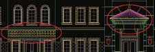
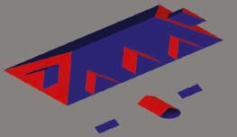
In this approach, you simply detach all of the coplanar faces into single objects and apply a single UVW Map modifier to each separate object. In Figure 5-8, you can see 5 separate object colors, which indicate that there are 5 separate objects. Each surface with the same color is coplanar, or very close to being coplanar. Because of this, the shingles that are applied to them should be oriented in the same fashion, and because the shingles are oriented the same way, they can all use the same UVW Map modifier. The round section of the roof shown at the bottom of the illustration would need spherical mapping applied, but all other surfaces would only need the default planar mapping.
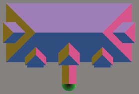
Figure 5-8. An example of breaking a roof apart into separate objects of coplanar faces.
In Figure 5-9, you can see an example of one object receiving a shingle material. All of the coplanar (or nearly coplanar) polygons receive the same material and mapping. Also, notice in the right image that the UVW Map gizmo has been rotated so it becomes aligned to the surfaces receiving the material. Sometimes, the benefit of this is minimal, while other times it can be quite dramatic.
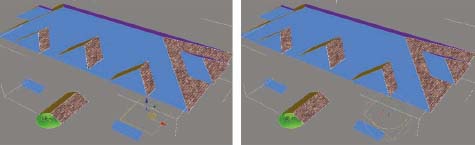
Figure 5-9. All of the coplanar faces of a roof attached together as one object receiving the same mapping.
As a final note, when creating shingle roofs, don’t forget to apply ridge and valley caps as shown in the previous exercise with standing seam roofs. You can even use the same profiles used in the last exercise. Excluding this kind of detail can really hurt the realism of a visualization.
Summary
This chapter provided an in-depth look at the creation of the generic roof structure and the application of the three main types of roofs we typically need to create for visualizations. Someday, we might be fortunate enough to have a tool available that will allow us to quickly place 3D tiles on our roofs, but until then, there is simply no way to get around the fact that the placement of tiles is a meticulous and often time-consuming endeavor. Standing seam and shingle roofs are much easier to create by comparison and certainly don’t put the same kind of strain on your computer’s resources. Nevertheless, with an object as big and prominent as a roof usually is in a visualization, you should take whatever time necessary to ensure that this important building element is created as effectively as possible.