
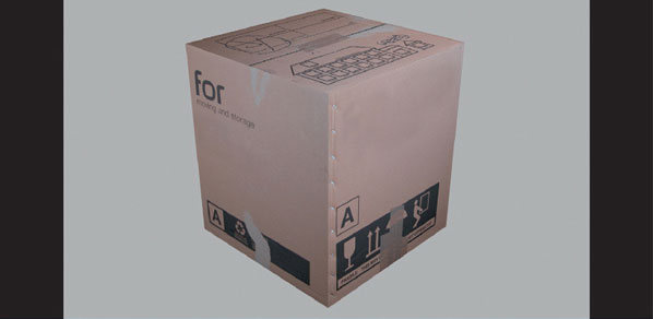
Creating, Unwrapping, and Texturing Simple Models
For our first model, we’re going to create a box. Go to the Main Menu > Create > Standard Primitives > Box.
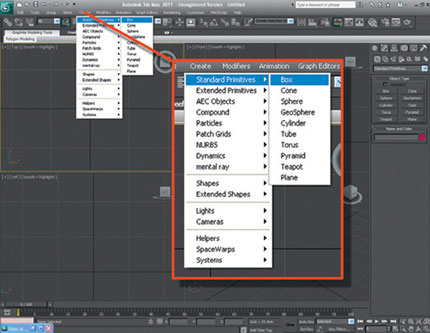
FIG 2.1
Left-click and drag in the viewport to create the box. Click again to finish. Now set the dimensions to 45 × 45 × 50 in the modify panel to the right. If your box is being displayed in wireframe in any of your viewports, just click on the viewport and press the F3 key.
You can also create primitives from the create panel to the right. Ensure standard primitives appear in the drop-down box. Then choose box from the object type panel and left-click and drag in the viewport to create the box the same way as in the previous method.
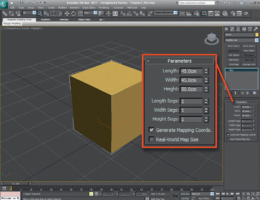
FIG 2.2
With the box selected, right-click it and select Convert to Editable Mesh from the Quad Menu.
Now you need to save your progress. Always name your files with a relevant name to make it easier to find your assets later on. As this is the first save file, we’ll create a few folders to store all the files that you’ll be working on while using this book. Go to save the file (File > Save as …), create a folder called 3D Modeling for Games, then create another folder inside the one you’ve just created called Chapter 1. Now save your file as Cardboard box1.max or Chapter1_001.max.
We have completed the modeling part of this tutorial. Now we have to apply the texture maps to the faces of the box and our first asset will be complete.
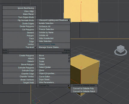
FIG 2.3
There are a few viewport configurations to help you to speed up the mapping of the box. Go to Modify, click the Configure Modifier Sets button, and select Show Buttons from the menu as shown in Fig. 2.4. Then select Configure Modifier Sets (Fig. 2.5).

FIG 2.4
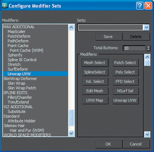
FIG 2.5
This action displays a set of buttons beneath the Modifier List rollout menu that can be configured to have all your most often used modifiers. Set the Total Buttons value to 10 and add Edit Mesh, UVW Map, and Unwrap UVW to the buttons, as we will use these modifiers the most in the first few chapters of the book. Do this by finding the modifier on the alphabetized list and drag it onto the button. To find a modifier on the list easily, just keep typing the first letter of it on the keyboard and you will cycle through all the modifiers with that letter (e.g., press “E” for Edit Mesh). Then click OK to close the Configure Modifier Sets window.
With your box still selected, go to Selection section of the modify panel and click Element, and select the box. This should highlight all the faces (press F2 to toggle the highlighted selection).
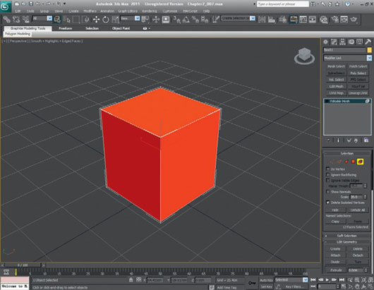
FIG 2.6
Now click UVW Map from your newly created modifier set and check Box Mapping from the Parameters menu.
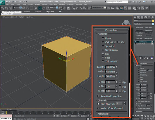
FIG 2.7
Next, right-click UVW Map in the Modifier stack and select Collapse All from the pop-up menu, then click Yes; you want to continue at the prompt, as we don’t need to preserve the stack in this instance.
With your box still selected, click on the Material Editor (on the top toolbar or press “M”) and change the standard material to a multi-sub object material as shown in Fig. 2.8, and click OK to discard the old material. If you keep the old material by accident, don’t worry; it doesn’t matter either way in this instance, as we are creating new ones.
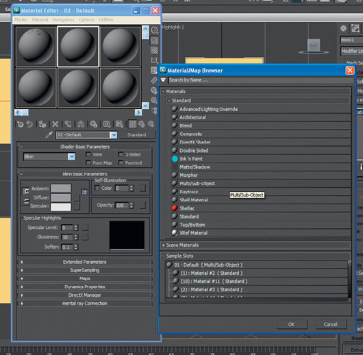
FIG 2.8
To keep this tutorial simple, I have already prepared the texture maps that you’ll be using from photographs. Later on in the book, we will discuss creating textures from photographs and applying them to models.
To add the textures into the Material Editor, select the material ID from the vertical list and load in the texture map for each side of the box. Although there are 10 materials displayed in the editor, we’ll just use the first six listed: Material #2 through Material #7 in my case. Yours could have different names, depending on how you have used 3ds Max previously. Don’t worry if your names don’t match mine at this point, as they can be renamed.
Click on the first material in the list, next to ID 1 (Material #2 in my case) and assign a Bitmap material to it. To do this, first click on the Sub-Material (Fig. 2.9), click the small square button to the right of “diffuse” in Blinn Basic Parameters (Fig. 2.10), select Bitmap from the top of the pop-up menu (Fig. 2.11), and click OK.
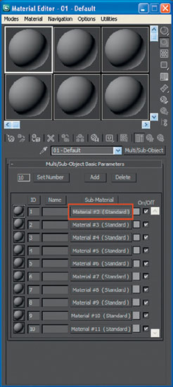
FIG 2.9
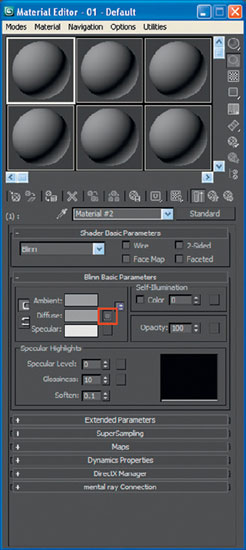
FIG 2.10
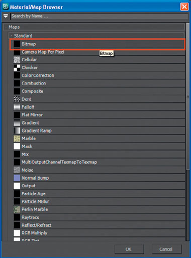
FIG 2.11
Now load Box1_top.jpg from Chapter 1Textures from the download area on the Web site. Please refer to the introduction in this book for full instructions, or go to www.3d-for-games.com, click on the Books and Media tab, and then click on 3ds Max Modeling for Games 2nd Edition and the downloads for each chapter will be in yellow at the bottom of the page.
There are two ways to assign the next material to ID 2. The first way is to click on the Go to Parent button (Fig. 2.11a), and then select the second material in the list or click on the Go Forward to Sibling button (Fig. 2.11b), which will go straight to the Blinn Basic Parameters of the next material.

FIG 2.11a
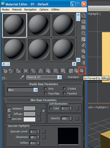
FIG 2.11b
Then repeat the process of clicking the small square button to the right of “diffuse” and selecting Bitmap from the top of the pop-up menu, and clicking OK.
As you assign each material a texture map, click the Show Standard Map in Viewport button (![]() ) so that when you Assign Material to Selection, the textures are visible on the object.
) so that when you Assign Material to Selection, the textures are visible on the object.
Repeat this process for ID 2 through ID 6, loading the remaining five texture maps into the Material Editor and ending with Box1_base.jpg being assigned to ID 6.
Here’s how they should be assigned:
ID 1 — Material #2 — Box1_top.jpg
ID 2 — Material #3 — Box1_sid1.jpg
ID 3 — Material #4 — Box1_ sid2.jpg
ID 4 — Material #5 — Box1_ sid3.jpg
ID 5 — Material #6 — Box1_ sid4.jpg
ID 6 — Material #7 — Box1_base.jpg
Remember that your Material number may differ from the numbers I have. As long as you match the ID (number)—for example, ID 1 goes with the corresponding texture map, in this case Box1_top.jpg—you’ll be okay. Also make sure that you remember to select Show Standard Map in Viewport ![]() .
.
Now that we have assigned texture maps to all of the materials, we will apply the material set to the box and apply the material IDs to the faces of the box, allowing us to see the texture maps.
With the box still selected as an editable mesh, click the Assign Material to Selection button to assign the material set that you’ve just set up to the box you’re mapping (Fig. 2.12). At this point, you should see that a lot of the box’s faces now have texture maps on them. These currently correspond to the default face IDs, which are not necessarily the ones we want, so let’s go through and check each face of the cube individually to make sure that the correct texture map is applied to the correct face on the box.
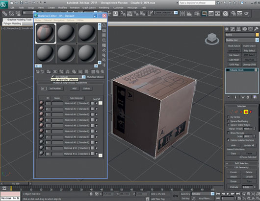
FIG 2.12
For this model, we must do this carefully, as some of the packaging tape on the box wraps around onto the adjacent faces. Look out for mistakes when you complete the model.
To get the correct map onto the correct face, first select the face of the box that is on the top of the box in the Perspective viewport. Go to Selection and select Polygon. Scroll down from selection until you get to the Surface Properties rollout box and in Material, make sure that Set ID is set to 1.
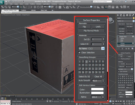
FIG 2.13
In the Perspective view, select the polygon on the left-hand side and assign the ID to 4. Depending on how the box mapping oriented each of the box’s faces when we mapped it, the texture map may not be oriented the correct way. If this is the case, we’ll need to modify the UVW Mapping co-ordinates to correct it.
From the Modifier List, click the button Unwrap UVW, which adds the Unwrap UVW modifier to the modifier stack (Fig. 2.14). Below the modifier stack, adjust the vertical scrolling menu until you find Parameters. Once you have found the Parameters section, click Edit. The Edit UVW window will pop open.
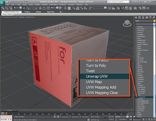
FIG 2.14
From the pull-down menu at the top right of the new Edit UVW window, click on the rollout, and select Map#1 (Box1_side1.jpg).

FIG 2.15
Now we need to select all of the vertices (left-click, drag bounding box around all vertices, then release the left mouse button). You’ll know if you’ve selected them all as they all change to a red color.
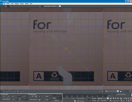
FIG 2.16
Now we need to rotate all the vertices to the correct orientation on the cardboard box, but first press the “A” key on the keyboard to activate the angle snap shortcut. We rotate the vertices (select Rotate at the top left of the Edit UVW window) until the text on the texture map is the right way up on the cardboard box model in the viewport.
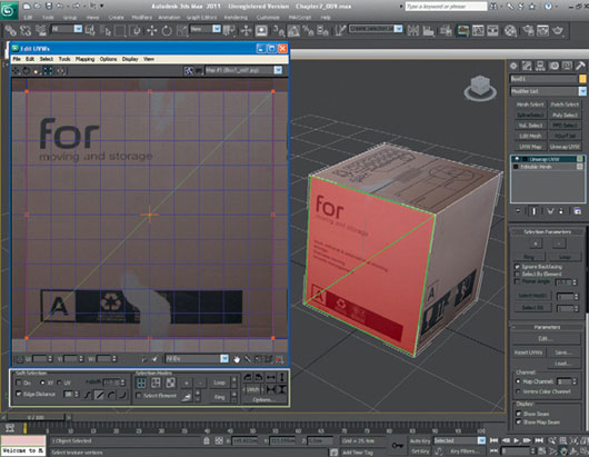
FIG 2.17
There are a few options that I like to set to help me see the map more clearly when doing this type of mapping. At the bottom right-hand corner of the Edit UVW window, click Options. This step brings up some extra settings for editing the UVWs. Uncheck Tile Bitmap and set Brightness to 1, which is useful in that it will help you see the texture sheet a lot more clearly. This option can also be set from the top menu, by selecting Options > Preferences (Ctrl + 1 + O) and adjusting it in the Display Preferences menu.
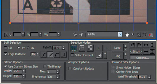
FIG 2.18
Next, right-click Unwrap UVW in the modifier stack and select Collapse All, then select Yes, to clear the stack.
Now we’ll continue mapping the rest of the cardboard box. Left-click on Editable Mesh in the Modifier Stack and press the “4” key on the keyboard, which is the shortcut for Select Polygon.
Other useful shortcuts of this type are as follows:
1 Select Vertex, 2 Select Edge, 3 Select Face, 4 Select Polygon, and 5 Select Element.
With Edit Polygon selected, select the other visible front polygon in the Perspective view, repeat the mapping and unwrapping procedure on the second side that you can see in the Perspective viewport, but this time, set the ID of the face of the box to ID 3.
To see what you are doing more clearly in each of the viewports, right-click on the name of the viewport and select Smooth and Highlights from the pop-up window.
On this occasion, the second box side texture map on my model is the correct way up, so there is no need for me to unwrap the UVs. If yours doesn’t match this, repeat the previous process.
To help you to see the model more clearly while in the Perspective view, click on the Maximize Viewport Toggle (bottom right of interface). Now click on Arc Rotate Selected (to the left of the Maximize Viewport Toggle) and rotate the object so that you can clearly see the rear two sides of the cardboard box. You can also close the Material Editor or minimize it for a good look at all sides too. Feel free to have a play with the new floating controllers (in the top right) of each viewport to change your view, too.
Select the polygon on the left and assign it ID 2. If the texture map is not orientated correctly, quickly correct it by following the mapping procedure from mapping the first side of the box (Unwrap UVW, Edit, Select Map#2 box_sid1.jpg, select vertices, rotate to correct orientation).
Collapse the stack again, press “4,” and select the fourth side to map. This time, set the ID to 5 and adjust the UVW Mapping, if necessary, so that it matches the example.
Finally, rotate the Perspective view (Arc Rotate Selected button) and select the bottom polygon of the cardboard box. Set the ID to 6 and adjust the mapping, if necessary. On this side of the box, pay close attention to the packaging tape on the texture map and make sure that it lines up correctly with the tape wrapping around onto the sides of the box. Once you’re happy with it, that’s it—you’re done.
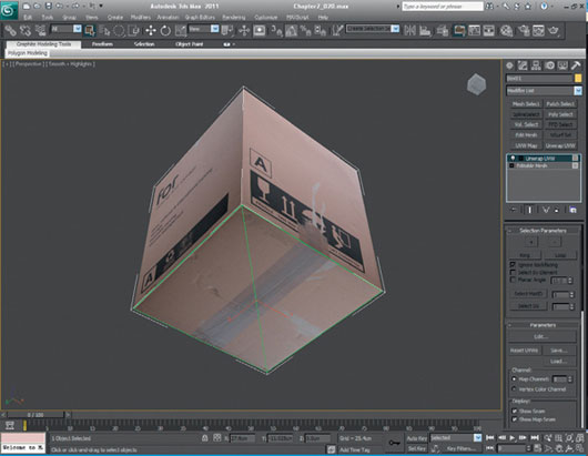
FIG 2.19
When building assets like this one, always make sure that all of the texture maps are the same size and resolution. Differences in resolution have a massive impact on the quality of your finished model, and even if the maps are supplied to you, always check their size and color depth to make sure that they match where they should.
With models containing patterns that wrap around the object, make sure that they line up correctly on all sides.
To produce quick renders of your model for an object database or for a progress portfolio, first we need to set up the environment.
At the top of the screen, select Rendering then Environments and Effects from the drop-down menu, or alternatively press “8” for the shortcut.
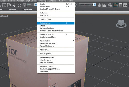
FIG 2.20
For this type of quick render, I usually set the Global Lighting Ambient to around 150, the Tint to approximately 200, with the intensity at 0.5, and the background color set to something neutral or close to white (around 230). In this case, as I’ll be using the render just to put in a progress portfolio, I’ll be using 230 for the background. It will help the object stand out and will be a lot less messy to print in color.
Once you’re happy with the settings, close the Environment and Effects window, and rotate the viewport until you’re satisfied that the view is showing off the best of the model. I like the detail in the cardboard on the top of the box, and I also like the staple details with the rips on the sides, so they will be most prominent in my render.
Go to Rendering > Render Setup or type F10 as a shortcut, opening up the parameters for the scanline renderer. In Output Size, click the 800 × 600 button, and click the Render button (bottom right of parameters pop-up). You should now have a render of your cardboard box. If you want a render that is of a slightly higher resolution, instead of clicking the 800 × 600 button, click the Image Aspect lock button and type in 1920 (or whatever size you like) and press Return and then the render button. You can render images at any size you like.
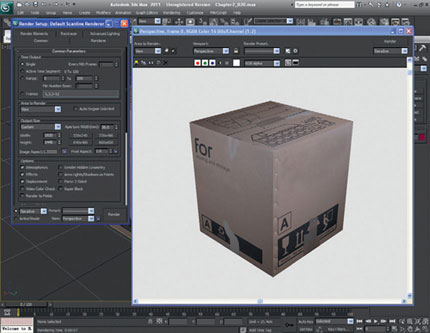
FIG 2.21
Try adjusting the Ambient Light, Tint, and Background color settings until you render an image that you’re happy with. But keep the render nice and clean if it’s for a portfolio. You can always add it to a themed style sheet in Photoshop for your final portfolio later. Keeping it clean will enable you make any style changes later on a lot more easily.
Congratulations on getting to the end of this build. If your final model is slightly different to mine, don’t worry too much, as long as you understand the process, and that’s the main point.
If you didn’t quite manage to understand everything, or if you have any questions, just log onto www.3d-for-games.com/form, and we’ll answer your questions as soon as you’ve registered and logged in. Start by saying hello in the welcome thread, and then post up your questions in the support thread.
Model 2—Creating a Plastic Barrel
Ok, so hopefully you’ve managed to complete the cardboard box tutorial in part 1 without encountering any problems.
If you skipped the tutorial, try to at least flick through it so that you know what we’ve covered just in case we’ve mentioned something we don’t go back to again.
As we have so much great content to cram in this one book, we’ll really try not to repeat things, so that you get the absolute best value for your money. Because of this, I advise you to complete the tutorials in order so that you don’t miss anything; even if you know what you are doing, at least skim read them as there could be something important that you miss, which could cause problems for you later on.
Ok, let’s move on with the modeling.
This time, we will be creating another primitive object and using a lot of different actions, including Editable Poly, Select and Uniform Scale, loading background images, keyboard shortcuts, object properties (See-Through and Backface Cull), Boolean (Cut & Union), deleting faces, and Target Weld for vertices.
For this tutorial, we will use some reference photos. These photos have already been provided for you and can be downloaded from the Web site. Please refer to the introduction of the book for details on how to get these.
To build this model, we will be doing slightly more modeling than the first tutorial and a little more complex mapping; but don’t worry, we’ll guide you through this, step by step.
We will use the reference photos as a guide to model from, and we will use them again to create the texture map.
First, open up 3ds Max and start with a new scene (File > New, select the New All, and click OK). The first thing we need to do is load the first photo into 3ds Max to use as a guide. To do this, while you’re in the Top viewport, press Alt + B to import a background image.
Make sure that you check the options Match Bitmap, Display Background, and Lock Zoom/Pan. From the chapter files, open Img_0301.jpg from Chapter2CH002_Textures, and then click OK. You could also create a flat plane of polygons and map the image to it for reference if you prefer.
You should now see the photograph of the top of a dirty plastic barrel in your Top viewport. Go to Create > Geometry, make sure that Standard Primitives is selected, and click on Cylinder.
Then click in the Top viewport, approximately in the center of the barrel in the photo, and create a cylinder that is roughly the circumference of the barrel. Don’t worry about the height at this point, as we will adjust it in a moment.
Next, set the parameters to 12 Sides and 3 Height Segments. Click Select and Rotate and rotate the cylinder so that the top and bottom edges are horizontal as shown in Fig. 2.23.
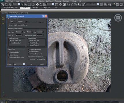
FIG 2.22

FIG 2.23
Now maximize the Top viewport (Alt + W) so that the top view is full-screen. Go to Modify and right-click on the cylinder and select Convert To: Editable Poly.
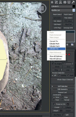
FIG 2.24
Feel free to modify the cylinder so that it matches the photograph more closely (as pictured in Fig. 2.25) using Select and Uniform Scale and Select and Move from the top toolbar.
Next click Editable Poly and select Vertex if it’s not already selected. We need to make the cylinder slightly squarer to match the photo by selecting groups of vertices and moving them either horizontally or vertically.
The completed shape doesn’t have to be perfect, so don’t spend too much time getting the form right. I used Select and Uniform Scale and selected four groups of vertices at a time. When you’re finished, the object should look roughly like Fig. 2.25.
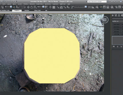
FIG 2.25
Click Alt + W again to reveal the other viewports and we’ll open up another image to use as a guide. While still in the Top viewport, click Alt + B and uncheck Display Background (because we are finished with that image).
Next, right-click on the Front viewport and zoom out from the barrel using Zoom Extents (in the bottom-right corner) and the left mouse button. If you aren’t sure what any of the buttons on the toolbar are, just hover your cursor over them for a second and a pop-up dialog box will tell you.
Now we’ve zoomed back from the image slightly, we need to import another background image (Alt + B).
Load in Img_0300.jpg from Chapter2CH002_Textures. This time, uncheck Lock Zoom/Pan and then click OK.
As this photograph was taken from a different angle to the model we’re building, I’ve unchecked Lock Zoom/Pan to let me rotate the object and zoom in and out. This will allow me to set the right height for the cylinder, which we’ll now call the “barrel.”
Click Select and Rotate from the top toolbar and rotate the barrel 90°, so that it lies on its side. If angle snap is off, turn it on (by pressing the A key) before starting to rotate the barrel.
You should be left with something that looks like Fig. 2.26.
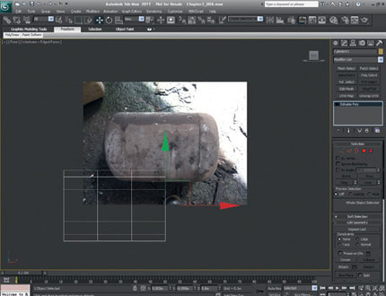
FIG 2.26
Using Select and Move, as well as Select and Uniform Scale, move the barrel over the photograph and set the height of it, so that it matches ours.
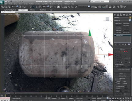
FIG 2.27
We have the basic dimensions of the barrel; we can start to model the details and make it look a bit more realistic.
As this is a low-poly object, we won’t be adding lots of details—just enough to round off the edges, and we’ll add the handle shape on the top. The rest of the detail will come from the texture map.
We need to create the slight curves to the top and bottom of the barrel.
To do this, we will scale the center vertices on the x-axis. Click Editable Poly, go back to the Front viewport, and drag-select the center vertices. Click Select and Uniform Scale and drag them out so that they look something like Fig. 2.28.
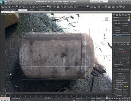
FIG 2.28
Click Editable Poly again to turn it off. Click Select and Rotate and rotate the barrel back 90° into the upright position that it was in earlier. Then click Alt + B and turn off Display Background. Finally, click Zoom Extents All (Shift + Ctrl + Z).
If you like, you can click in each viewport, and click F3 to toggle Wifeframe/Smooth + Highlight and also click F4 to toggle View Edged Faces, so that you can see the work you’ve completed so far, more clearly.
For details on the other shortcuts on the F (function) keys and all the preset shortcuts in 3ds Max, go to Customize > Customize User Interface and scroll down the list to see what the default hotkeys are.
You can also assign your own here, but remember, if you make any changes, save the settings.
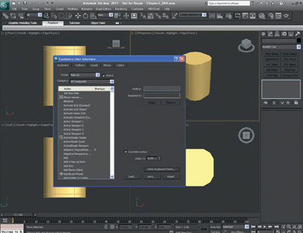
FIG 2.29
Ok, let’s continue with the model.
In the Front viewport, type 1. This selects Vertex in Editable Poly (try pressing the keys 2, 3, 4, and 5, one at a time, to see how these work as shortcuts). Type Alt + W and then drag-select all of the very top row of vertices, and then Ctrl + drag-select the very bottom row of vertices. Click T for Top viewport, and click Z for Zoom Extents.
Click Select and Uniform Scale and scale the vertices in to give a slight bevel to the top and bottom of the barrel. If you drag toward the center of the barrel when scaling, look at the co-ordinates at the bottom of the screen (just right of center). Drag until you hit 90%, which should look about right. Again, you don’t have to be especially accurate on this.
Click F to go to the Front viewport and scale the same set of vertices a little on the y-axis until your barrel looks something like Fig. 2.30.
There are two ways we can go with the build at this point. We could leave the model as it is now and create a texture map for it, and call that complete (which would be reasonable for a low-poly object), or we can model some detail on the top. In this case, we’ll model the detail on the top, as I want to show you a really cool tool called Boolean.
Type T to select the Top viewport, and then press F3 to see the wireframe of the barrel. Click Create > Standard Primitives > Cylinder and make sure that Height Segments is set to 1 and Sides is set to 12. Click in the center of the barrel and create a cylinder that is about half as wide as the barrel.
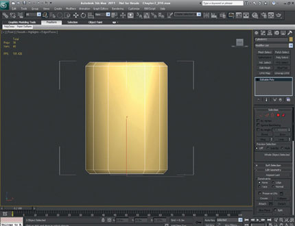
FIG 2.30
Type F for the Front viewport, and then press Shift + Ctrl + Z to Zoom Extents. You should now have the barrel and also a cylinder in the scene. Click Select and Move, and move the cylinder up so that it intersects with the top of the barrel.

FIG 2.31
Remember to regularly save your work as you model. It’s really easy to get swept away with the progress, and you can spend many hours on something—only to lose it all in a crash. Try to save regularly and have the autoback function set. We all usually only remember to save just as our computers crash, which is obviously too late.
Let’s move onto Boolean. Select the barrel and press P (for the Perspective viewport) and F3 if the meshes aren’t Smooth and Highlight–shaded. Click Create, where Standard Primitives is displayed, click on the rollout menu, and select Compound Objects.
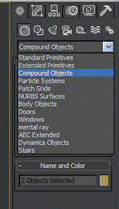
FIG 2.32
You should see Morph, Scatter, Conform, ShapeMerge, Boolean, and others. Boolean is a powerful tool and can be quite confusing until you get the hang of it. First, you need two objects; it works best with solid “closed meshes,” that is, where there are no holes in the mesh.
These are called Operand A and Operand B. Think of these as Shape A and Shape B. There are four different types of Boolean in 3ds Max 2011—Union, Intersection, Subtraction, and Cut. If you search for “Boolean Compound Object” in the 3ds Max 2011 help (F1) or the InfoCenter, it explains what all these are in detail. It is well worth reading the explanation and then creating two objects in a different file and playing with the different types to see what results you can get.
For this model, we will be using Cut. With the barrel still selected, click Cut from the Operation selection on the right of the workspace, then click Pick Operand B (choose the other shape), and then click to select the cylinder, as shown in Fig. 2.33.
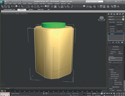
FIG 2.33
This step will cut the barrel with the shape of the cylinder, but leave you with a solid mesh.
To finish off the Boolean work, click on Modify, right-click on Boolean, and select Editable Mesh.
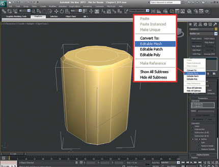
FIG 2.34
One of the most important parts of modeling something that you haven’t modeled before is that you may not build it perfectly from start to finish, and you may have to modify your work. This approach can be a lot quicker than going back to a save file or (even worse) rebuilding something. If you’ve followed the tutorial accurately up to this point, you will have made a small mistake that was included deliberately on the last action. Before we performed the Boolean, it would have made progressing easier if we had rotated the cylinder that we were using to cut, so that the top and bottom edges were horizontal. Rather than going back to a previous save file, we’ll just fix it at the polygon level.

FIG 2.35
First, you need to be in the Top viewport. Make sure that the barrel is still selected and type 4 to go into polygon mode. To make sure that you have the center polygons selected, press F2 (Shade Selected Faces Toggle) to display what you’ve got selected. If you don’t have a mouse with a scroll wheel, it’s a good idea to get one, as the wheel can be used to zoom in and out of the scene.
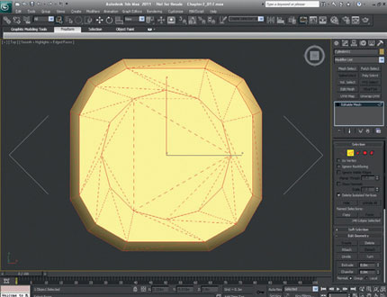
FIG 2.36
We need to rotate the polygons only a small amount, but looking at the barrel, it’s impossible to see which way it should be. So we need to have a look at the edges of the polygons. Press 2 and drag-select the whole barrel. This step will show you where all the hidden edges are.
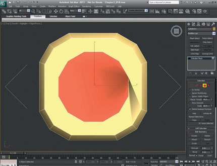
FIG 2.37
There are two ways to line the polygons up the way we want them. The first is to select just the edges we want to rotate and then rotate them, but the quicker way is to press 4, make sure the center polygons are selected, and rotate them making sure that angle snap (A) is on.
As you can see by the shadows that have appeared on the surface (smoothing), we have turned some of the polygons so that they now overlap. We just need to type 2 to modify the edges again and then select Turn from the Edit Geometry toolbar on the right.

FIG 2.38
Then we just need to click on the edges that are cutting through the corners of the central circle of polygons on the top of the barrel, turning them so that the polygons no longer overlap. If you see any other particularly long and thin triangles, you might want to turn the edges of those too, to tidy up the mesh.
Next, we will add the final details to the top of the barrel. First, let’s extrude the center polygons to create the dip in the top of the barrel; then, we’ll create a simple handle form.
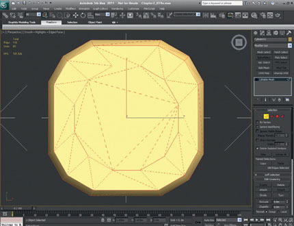
FIG 2.39
Press P to jump into the Perspective window, and then press Z (Zoom Extents) so that you can see what you’re doing. Buttons like Zoom Extents (Z) have a small triangle in the corner to show that they have multiple options. Left-click and hold on the triangle and the various options will be made available. In this case, there are two options: Zoom Extents and Zoom Extents Selected. I usually prefer Zoom Extents Selected, as it zooms into the selected part of the model only, usually making it easier to work. Have a look at all the other buttons and get familiar with what they do—getting up to speed with these early will save you a lot of time.
Next we need to extrude the top center polygons to create the sunken form of the top of the barrel. Still in Editable mesh, select Extrude from Edit Geometry, then click on the center polygons (select them if they have been unselected), and drag the mouse toward yourself. This will create the extrusion. Obviously, if you had clicked and pushed forward when extruding, you would have created the same form, but as an addition to the geometry rather than a subtraction. Next, just scale the polygons to create the indentation on the top.
Now, we need to create a handle. We’ll use Boolean again, as it’s nice and quick.
From the Top viewport, create a new cylinder in the center of the barrel. Give it eight sides and one height segment, and rotate it so that the top and bottom edges are horizontal. Then convert it to an Editable Mesh and scale it to the rough shape of a handle.
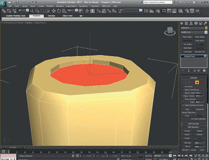
FIG 2.40
Make sure that the handle shape intersects with the barrel shape, as we will be using Union, but also that it stays in the center of the barrel and doesn’t overlap the sloped edges of the indent. Just before performing the Boolean, select the barrel instead of the handle.
As before, select Create, Compound Objects, Boolean and make sure that Union is selected, click Pick Operand B, and then click to select the handle. Don’t worry if the barrel suddenly changes color. It is just picking up the material from the cylinder (meaning that you didn’t select the barrel before picking the handle as the Operand B). If this happened, just undo and try again. As we’ll be texture-mapping the barrel, the color of the base material doesn’t matter, but you may pick up some properties from the handle that could affect the way we map the barrel, so make sure you have the barrel selected before you click Operand B.
As we left a small gap between the handle and the edge of the barrel on the top of the barrel, let’s join that up next. First select Modify, and then right-click Boolean and convert to Editable Mesh.
As we’re not sure what the Boolean has done to the mesh, let’s have a look by going to Edge select (press 2) and drag-selecting all the edges on the top of the barrel (or using Ctrl + A). As you can see, there are a few of really thin polygons around where we join the handle and the barrel together, so let’s clean them up by selecting Edit Geometry and Turn. We’ll turn each of the long edges until we get something that looks like Fig. 2.42.
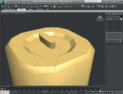
FIG 2.41
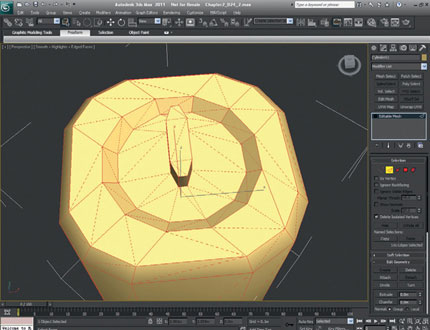
FIG 2.42
Remember to confirm that Ignore Backfacing is selected so that you don’t accidentally turn edges on the back of the object by mistake. Errors like this can be quite time-consuming to fix if they go unnoticed—as you won’t really want to use Undo if you’ve done a lot of modeling. Extra care should also be taken when welding vertices, as the errors can be difficult to undo if unnoticed.
Now we’re going to weld a couple of vertices to make the handle look a little more realistic and like the reference.
First, select Edit from the main toolbar at the top of the screen and select Object Properties to open a pop-up box. In Display Properties, check Backface Cull, and click OK. By checking Backface Cull, all the polygons will be displayed only as one-sided. Next, we need to delete a few polygons and weld the vertices to fill the hole. If you weld the vertices first, you may unknowingly create some inner-facing polygons. Not only will these affect the smoothing on the object, but they can also make some of the UVW unwrapping confusing.
Now let’s delete the unwanted polygons. Rotate the barrel until you can clearly see the far side of the handle. Now we’re looking to delete the three polygons that make up the join between the handle and the edge of the barrel. Type 3 to select Face Selection and make sure that you can see which faces you have selected. Select the six faces, and click Del to delete them.
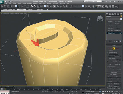
FIG 2.43
Next, we need to fill the gap by target-welding the vertices. Hit 1 to go to Vertex selection and select Target from the Weld menu. Select the vertices on the open edge of the handle and drag them onto the vertices of the edge of the barrel.
If the vertices seem to be sliding on a single axis, press F8 and then try again. You should now be able to move the vertices on multiple axes. Even without clicking F8, if you were to drag the cursor onto the correct vertex to weld, it would still have done it correctly. If you rotate the barrel around, enabling you to see the back of the handle to complete the weld accurately, you should end up with a shape as shown in Fig. 2.44.
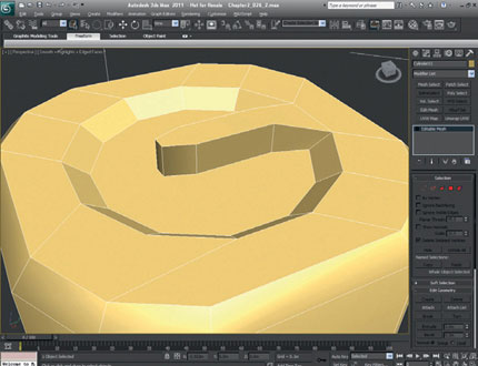
FIG 2.44
Now that we have the basic form of the top of the barrel, we need to compare it with the reference photo again and manipulate the top vertices so that they match the photo. Type T for Top viewport, and then press Alt + B to load up the background image. Select Img_0301.jpg Chapter2CH002_Textures and select Lock/Zoom Pan and Display Background, and click OK.
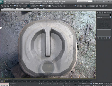
FIG 2.45
There are a couple of different ways in which we can manipulate the model and still see the reference photo. One is by pressing F3 to toggle wireframes, and the other is to set the image so that it is see-through.
With the object selected, right-click on it to open up the Options fly-out. In Transform (bottom right), select Object Properties, select See-Through from the Display Properties, and click OK.
This option changes the look of the object, enabling you to see both the polygons, as well as the reference photo behind it. Now we just need to match up the vertices with the photo using Select and Move and also Select and Uniform Scale. To accurately select the lower vertices to taper the handle, jump into Perspective view and select them individually before returning to the Top viewport to spread them out.
The last part of modeling that we need to complete before we start texture-mapping is the flattened area around the spout. In the Front viewport (shortcut F), make sure that the top of the handle is flush with the top of the barrel and that the vertices are laid out similar to Fig. 2.45.
Press F3 and rotate the barrel slightly forward. Select the two edges on the top of the barrel nearest to you and move them down so that they are level with the indent on the top of the barrel. Once we’ve selected the edges, we need to jump back to the Front view (shortcut F) so that we can see how far we need to move them down. Hit F3 to make this easier. Moving these edges down has highlighted how a few of the edges need to be turned so that the curves on the barrel look more realistic.
Press F2 and then Ctrl + A to display all the edges. Have a look to see whether you can improve some of the curves by turning edges. This isn’t important; it just improves the form of the model when viewed from some acute angles.
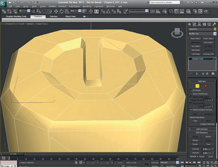
FIG 2.46
Creating the Texture for the Barrel
There are a few different ways to create texture maps for models like this, but I’ll show you the method that I think is most appropriate for this exercise.
First of all, we need to think about how the barrel texture can be laid out or unwrapped. We want to represent the key components of the photos, and we want the barrel to look as realistic as possible when we finish.
For this model, I think that there should be three main parts to the texture map: the top, the bottom, and the sides.
To make the model look realistic when it is mapped, we want as few joins on the texture map as possible, as all of the edges on this model are rounded. If we were modeling an asset like the cardboard box again, this issue wouldn’t matter, as the joins on each of the sides are hidden by the corners and also by the smoothing groups. But for this model, we’ll need to treat the edges differently.
Although the barrel shape has flat sides, its corners are rounded, so in this instance, we should consider mapping the sides with cylindrical mapping. This means that the texture for this part of the model needs to “tile” (that is, to wrap seamlessly around the model).
With this in mind, we will dedicate most of the texture page to the sides, but we’ll also make sure that it covers the top area of the texture completely (from left to right) so that we can use the Offset tool in Photoshop. This approach will enable us to tile the texture and thus to seamlessly map all the sides on the barrel.
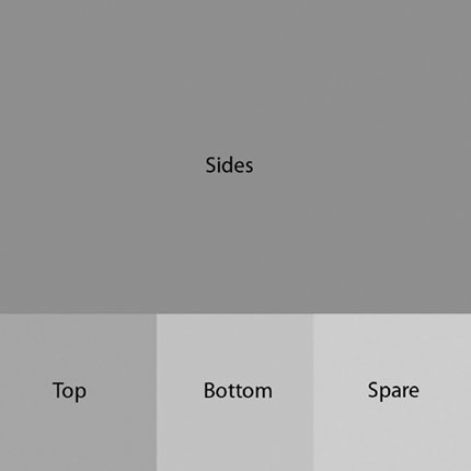
FIG 2.47
To keep the texture resolution roughly even across the model, allow the top and bottom of the barrel around 30% of the height of the texture page as shown in Fig. 2.47.
Dividing up the texture map in this way should give us plenty of room for the top and bottom details and also enable us to tile the side’s part of the map easily in Photoshop. It does, however, leave us a small area spare. We can use this for any extra details that we haven’t thought of yet, or maybe a label or some other feature not on the source photo. Dividing up the texture page, in this way, will mean that we will not be using each side of the barrel directly from the photograph.
As texture pages need to be either square (512 × 512) or divisible by two (1024 × 512), we would have to cram and stretch the four sides of the barrel into this area, which wouldn’t really work, as it would cause distortions.
A texture that is divisible by two could be used, which would give us plenty of room for the four sides and the top and bottom, but again we would still be stretching the photo reference to use the texture page efficiently, so we will opt for the first layout, as it is closer to the reference.
Obviously, if you never intend to put your texture maps into a game engine, you could make them any size or shape you like. The best way to do this is to model your barrel, then take screen grabs or wireframe renders of the front, sides, top, and bottom, and use them as a guide for your map. There are also other plug-ins and tools that help, but these are the simplest methods to get you started.
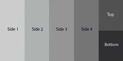
FIG 2.48
Let’s get started with the texture map creation. First, open up the reference photos from the project files Chapter2CH002_Textures and paste the components that you’d like to see on your texture map into a new Photoshop file. Once you have the main components for the sides, crop the image and save it out. Next, flatten the image by going to Layer > Flatten Image. This step should give you with a nice canvas to start to work on.
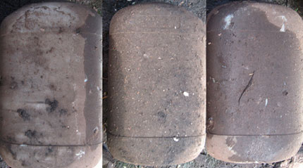
FIG 2.49
Next, use a combination of the Clone Stamp tool (shortcut S) and the Healing Brush tool (J) to cover up the parts of the texture map that we don’t want. Start with the really dark areas and the lines that don’t line up by replacing them with the more generic parts that we do want. If you have an older version of Photoshop, you’ll probably just have the Clone Stamp tool. Don’t worry—you’ll do just fine using that.
If you haven’t used these tools before, here are some basic instructions. Start by holding down Alt and left-clicking the area of the texture map that you want to clone from, then just left-click and hold to paint over the area that you want to change. Experiment with the opacity settings of the tools for varied effects.
One thing to watch out for when creating texture maps with these tools is not to repeat obvious areas of the texture. This sort of repetition really stands out and ruins the illusion of your model being real. Any bright spots or dark creases should only exist once or be completely removed. The horizontal lines around the barrel should be removed too, as we’ll add these back in later.

FIG 2.50
As you can see from this image, after only a few minutes of cloning and healing, the texture map is starting to take shape.
Continue this process until you have eliminated all the areas of the texture map that we don’t need, and you have a fairly generic barrel texture. If the Healing tool is taking a long time to calculate, just resize the image so that it is smaller and use slightly shorter brushstrokes; this should improve the update speed.
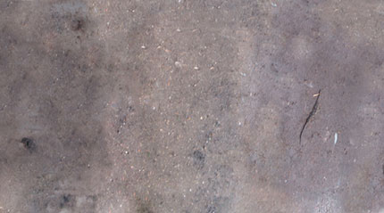
FIG 2.51
Let’s next make sure that the image tiles. To do this, we use the Offset tool in Photoshop: Filter > Other > Offset and select an offset so that the join mark is roughly in the center of the image.
Use the same Heal and Clone tools to remove the join line down the center of the texture map. Once the join is removed, we can either leave the texture map as it is or offset it back to its original position. I always like to offset it back, but there’s no need, as this texture map now tiles on the horizontal axis. Once finished, you should end up with something like Fig. 2.53.
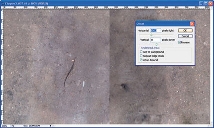
FIG 2.52
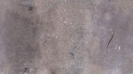
FIG 2.53
Now we need to add the other details of the texture map.
As we didn’t create the first part of the texture page with any size considerations, let’s do that next. We need to start to lay out the texture map so that the new components will be in the right place and at the right scale. We need to create a new image to lay out our map, so create a new file measuring 1024 × 1024 pixels.
Go to Edit > Preferences and set the rulers to measure in pixels, and then press Ctrl + R to show the rulers, if they are not already displayed. We next need to create a few guidelines to help us with the proportions of the rest of the texture. To do this, click on the ruler on the left-hand side of the image and drag a guide out to 341 pixels. Just drag it out to approximately 341 pixels and use the Move tool (V) along with the Zoom tool (Z) to make it accurate. Do this again from the left margin to 682 pixels and again from the top margin to 682 pixels. This should give you perfectly measured guidelines to fit the top and bottom of the barrel on the texture map.
Next, cut out the top and bottom of the barrel from the photo reference and lay them out in the gaps on the texture map.
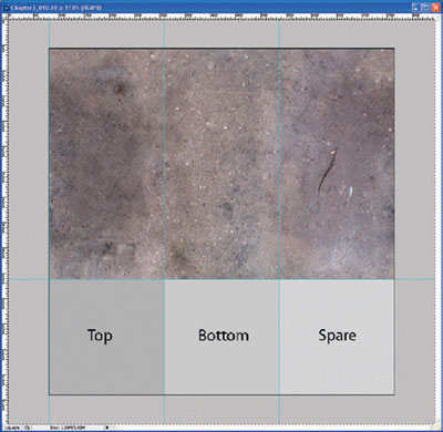
FIG 2.54
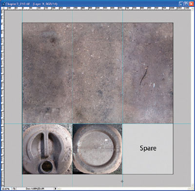
FIG 2.55
Then clone and heal the areas around the top and bottom of the barrel so that they blend into the surrounding area. You can adjust these joins once you have the texture mapped onto the model. We might make these areas slightly lighter or darker, depending on their corresponding edge on the model. We then fill in the blank space on the map with base texture or we can choose to leave it blank, so that we know there is some spare room on the texture map, should we come back to this model in the future to make changes or add details.
Finally, create a new layer and draw the dark and light lines across the sides to suggest that there is extra detail where there isn’t—and our texture page is complete.

FIG 2.56
Now we need to move on to texture-mapping the barrel. First of all, let’s get rid of the background image and return the barrel to solid shading (Alt + B, uncheck Display Background Image, click OK. Then right-click on the barrel, select Object Properties, uncheck See-Through, and click OK).
Next, we need to open up the Material Editor (on the top toolbar or click M). Then click the map button next to Diffuse in Blinn Basic Parameters. In Blinn Basic Parameters, click on the box next to Bitmap to load the texture and select Drum001_004.tif (Chapter2CH002_Textures), and click Open.
Next, click Assign Material to Selection; you should see the texture map applied to the barrel object.
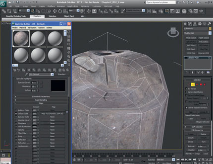
FIG 2.57
You can now close the Material Editor. At this point, although we have applied the texture map to the object, the only mapping co-ordinates on the barrel are from when you initially created it, so we need to apply new ones. We’ll map the sides of the barrel first, and then we’ll map the top and bottom.
Go to the Front viewport (F) and Zoom Extents so that you can see the whole barrel. If the top of the handle is sticking out above the barrel, select the vertices and drag them down so that they are level with the top of the barrel.
Select Editable Mesh if it isn’t selected already, and then select Edit Polygon (shortcut 4). Drag-select all of the barrel’s side faces, including the small bevels on the top and bottom. Take care not to select the extra polygons that make up the handle detail on the top.
Next, click UVW Map from the Modifier List, and check Cylindrical in Parameters > Mapping. On this model, we will try to wrap the top mapping over smoothly from the sides, so we also need to check Flip in the V Tile Mapping parameters. Press F3 and go to Perspective view to see what you have.
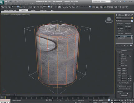
FIG 2.58
Although the mapping looks really rough and there seem to be parts of the barrel map everywhere, we should at least see the texture map wrapping continually around the sides of the cylinder.
Next, we’re going to slightly rotate the mapping on the sides of the barrel so that the top and the sides line up. Rotate your view around the barrel so that the handle is pointing away from you, and then click on UVW Mapping in the modifier stack to select the sub-tree (which will turn yellow to indicate the mode change). Then choose Select and Rotate and rotate the mapping (not the model), until the handle on the map roughly lines up with the handle on the model (even though it is below it).
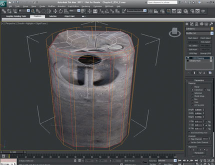
FIG 2.59
Next, we’ll adjust the UVW co-ordinates so that the top and bottom details on the texture map are no longer seen on the sides of the barrel. Select Unwrap UVW from the Modifier List and then select Edit from the Parameters rollout. The Edit UVW box should appear on screen.
Now go to the top right-hand corner, open up the drop-down menu, and select the texture map, which is map #1 in the list. This step shows the texture map and also how the polygons are laid out on it.
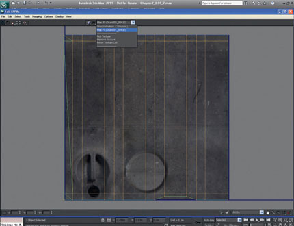
FIG 2.60
We now need to move some of the vertices around in the Edit UVW window so that the texture map fits our barrel model a little better. First select the bottom two rows of vertices in the window and move them vertically up just past the top details on the texture map. If you hold Shift down while you move them, they will move in a straight line up or across.

FIG 2.61
You can close the Edit UVW window now and have a look around your barrel. You should now see that the sides of the model are mapped. All we have to do is map the top and bottom, and we’re pretty much done.
As the top and bottom mapping will be pretty much the same, we can use one planar map to apply mapping co-ordinates to both the top and bottom. We will then unwrap them separately, as we have just done.
Now we will add Edit Mesh to the stack from the Modifier List. Then press 4 to edit polygons and from the top menu choose Edit > Select Invert (Ctrl + I) to select all the remaining polygons to map. You should now have all the polygons on the top and bottom of the barrel selected.
We now need to go to Top viewport (shortcut T) and click UVW Map and make sure that Planar is selected in the Mapping Parameters.
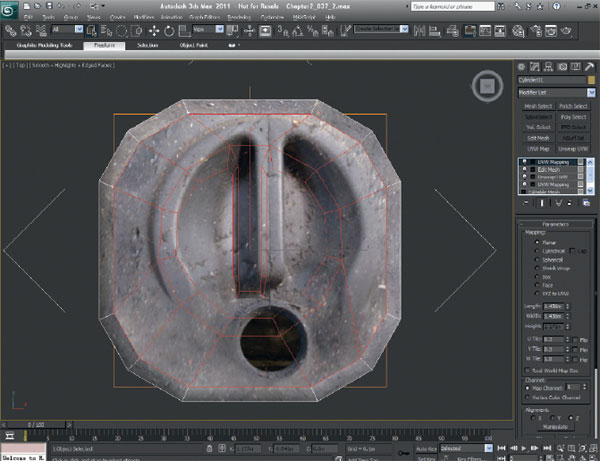
FIG 2.62
Scroll down the right-hand side to Alignment and select View Align. The texture map will be aligned to the Top viewport, not the model’s transform. Select Fit (still in Alignment) so that the texture fits to the selected polygons only, with no overlap.
Finally, in mapping, as we know that the top and bottom only take a small amount of the texture page, we can set the U Tile to 0.3 and the V Tile to 0.3. This step makes unwrapping the UVs a bit easier, as they are now closer to their final position. You should now see the texture map for the top of the barrel almost aligned.
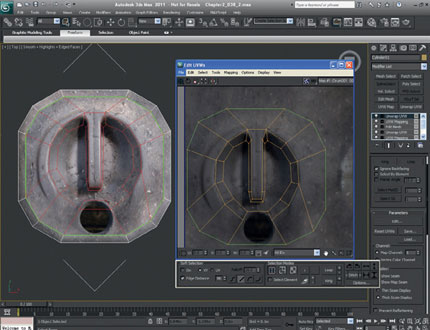
FIG 2.63
Select Unwrap UVW (from the Modifier List), and then select Edit and pick Map #1 from the drop-down menu in the Edit UVW window that appears. Using Zoom Region, we need to get in close to the vertices so that we can adjust the UVs accurately.
Click Ctrl + A to select all the vertices. Now we can scale them up so that they fit the rough shape of the barrel a little better. Don’t worry too much about getting them pixel-perfect at this point; we can always fine tune them later.
We can now close the Edit UVW window and have a look at what we have so far. To really see what we’ve got, we need to add another Edit Mesh to the Modifier stack and press F4 so that we can see the joins in the mapping between the top of the barrel and the sides.
Without using programs like Maxon’s BodyPaint 3D (www.maxon.net), it is extremely difficult to create textures that wrap seamlessly around 3D models; so don’t worry too much if you can see a slight edge. Most imperfections like this will never be seen in a game, so we don’t dwell on them. If however, you are working at a studio and this problem arises … well, you know what to put on your purchase request.
Now we’re on the home stretch. All we need to do is adjust the UVs on the bottom of the model and we’re done—or almost done.
Jump into the Front viewport and deselect all the polygons on the top of the barrel (hit F and then Ctrl + Alt + Z), and deselect the polygons on the top of the barrel (click Select Object and while holding Alt, drag and deselect the top polygons). Click P for Perspective view, rotate the barrel so that you can see the bottom polygons, and we’ll map the last part.
Once again, select Unwrap UVW from the Modifier List, select Edit (from parameters), and select Map #1 from the drop-down menu in the Edit UVW window that appears. All we need to do now is to slide the vertices along to the right to match up with the bottom of the barrel, and we’re almost done. Now click Ctrl + A to select all the vertices and move them into place using the Move tool.

FIG 2.64
Once again, close the Edit UVW window, apply an Edit Mesh to the model, and press F4 so that you can see the model fully mapped. If there are any areas that look stretched, select the polygons and edit the UVW unwrapping until you are happy. Render the model in the same way that you rendered the cardboard box from part 1, print it, and add it to your portfolio.
Congratulations! You’ve completed the second chapter, and I hope that you learned a few new techniques. With the skills that you’ve learned so far, you should be able to make almost any low-poly object. So well done—you’re well on your way.
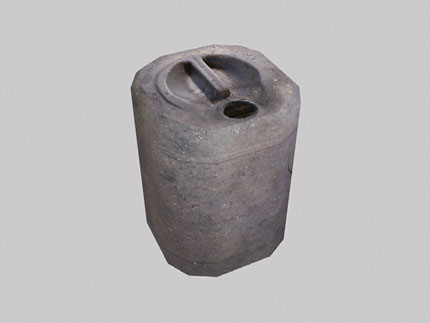
FIG 2.65